
mud pump piston rubber free sample

A wide variety of mud pump rubber piston assembly options are available to you, such as 1 year, not available.You can also choose from new, mud pump rubber piston assembly,As well as from energy & mining, construction works , and machinery repair shops. and whether mud pump rubber piston assembly is 1.5 years, 6 months, or unavailable.

A wide variety of mud pump rubber piston cup options are available to you, You can also choose from new, mud pump rubber piston cup,As well as from energy & mining, construction works , and machinery repair shops. And whether mud pump rubber piston cup is 6 months, {2}, or {3}.
TECHNICAL FIELD OF THE INVENTION The present invention relates generally to piston seals for mud pumps and more particularly to a replaceable piston seal. Still more particularly, the present invention relates to a durable polymeric piston seal constructed with very small tolerances so as to provide a precise interference fit with the corresponding liner.
Slush or mud pumps are commonly used for pumping drilling mud in connection with oil well drilling operations. Because of the need to pump the drilling mud through several thousand feet of drill pipe, such pumps typically operate at high pressures. Moreover, it is necessary for the mud to emerge from the drill bit downhole at a relatively high velocity in order to provide lubrication and cooling to the bit and to provide a vehicle for the removal of drill cuttings from the earth formation being drilled. Lastly, the pressure generated by the mud pump contributes to the total downhole pressure, which is used to prevent well blowouts.
The pistons and cylinders used for such mud pumps are susceptible to a high degree of wear during use because the drilling mud is relatively dense and has a high proportion of suspended abrasive solids. As the pump cylinder becomes worn, the small annular space between the piston and the cylinder wall increases substantially and sometimes irregularly. For these reasons, the seal design for such pumps is critical.
The high pressure abrasive environment in which the pumps must operate is especially deleterious to the seals since considerable friction forces are generated, and since the hydraulic pressures encountered during operation force the seal into the annular space between the cylinder wall and the piston. In some instances, the frictional forces may even detach the seal from the piston. In these instances, the edges of the seal can become damaged very quickly by the cutting or tearing action that occurs as a result of piston movement. Another problem with conventional mud pump seals is that they do not adequately "wipe" the
Attempts have been made to retain the seal in the piston so as to resist this frictional force. One conventional solution to this problem has been use of a metallic seal retainer which is disposed over the seal body and retained in place by snap rings. One disadvantage of this solution, however, is that the additional seal retaining element and its snap rings render the overall piston construction more expensive. A further disadvantage is that the seal is made somewhat less flexible and resilient than it would otherwise be, thus decreasing its ability to wipe the cylinder wall effectively. Another conventional solution to the sealing problem comprises including a seal retaining ring or reinforcement in the seal itself. In this case, the retaining ring or reinforcement is molded into the seal material. As with the external retaining ring, this solution decreases the flexibility of the seal and increases its cost of manufacture.
It is common to incorporate the foregoing seals into piston heads wherein the seal is permanently affixed to the piston head. This is disadvantageous because the seal tends to wear much faster than the piston head, resulting in waste and unnecessary expense when the whole piston head has to be replaced because of wear to the seal member. It is therefore desirable to provide a piston seal that is removable from the piston head and thus can be replaced without requiring replacement of the whole piston head. The nature of the mud pump operating environment makes it difficult to effectively address these issues. It is, therefore, desired to develop a new and improved replaceable seal for a reciprocating mud pump piston that overcomes the foregoing difficulties while providing better wear properties and more advantageous overall results.
BRIEF SUMMARY OF THE INVENTION The present invention comprises a new and improved replaceable seal for a reciprocating mud pump piston. The present seal does not require any external seal retaining means and is free from any incorporated seal retainer or reinforcement. The present seal is manufactured to precise specifications that minimize play between the seal, piston head and cylinder and also compensate for the slight deformation of the seal member that occurs when the seal member is demolded and cured.
Figure 3 is a cross sectional view of the sealing member of Figure 2 mounted on a piston head in a cylinder. DETAILED DESCRIPTION OF THE PREFERRED EMBODIMENTS
Referring initially to Figure 1, a typical prior-art mud pump piston assembly comprises a piston head 10 and a sealing device or seal 15 therefor slidably received in a piston cylinder 12. Piston head 10 comprises a generally cylindrical body having a flange 11 extending therefrom. Piston head 10 is typically made of steel, such as AISI 4140. Seal 15 is friction fit on piston head 10 and abuts flange 11. Seal 15 comprises an elastomeric sealing section 14 and a heel section 13. These sections are either integrally formed or bonded together. Heel section 13 is typically made from a stack of several layers of rubber- impregnated fabric, which give it a higher modulus of elasticity than the elastomeric sealing section 14. In prior art mud pumps, the heel section 13, which is stiffer than the elastomeric sealing section, resists extrusion into the gap between the cylinder and piston flange to some extent. However, heel section 13 is still forced into the gap under the influence of the hydrostatic pressure in locations where wear occurs. Reference numeral 18 designates a portion of heel section 14 that has been extruded into the gap 20 between the flange 11 and the cylinder 12. Both elastomeric sealing section 14 and heel section 13 make intimate contact with the cylinder 12. Seal 15 is held in place by a retaining ring 16 and a snap ring 17, which hold seal 15 in place and permit replacement thereof. Easy replacement of seals is a desirable feature for a mud pump, since seals typically wear out long before the other mud pump components and must be replaced in order to continue pumping operations. The direction of travel of piston 10 is shown by arrow 19. The direction of the hydrostatic pressure force exerted by the working fluid of the pump is shown by arrows 21. This force axially compresses elastomeric sealing section 14 and heel section 13 and radially expands these sections against the cylinder wall.
Referring now to Figure 3, the seal 22 of Figure 2 is shown mounted on a piston head in a cylinder. It can be seen that sealing lip 24 is compressed radially and conforms to the inside of 12. In addition, in order to enable seal 22 to be used without a reinforced heel section, piston head 10 is manufactured to extremely tight tolerances. In particular, it has been discovered that the life of seal 22 can be greatly prolonged by ensuring that play between flange 11 and cylinder 12 is minimized at the outset. Thus, the average width of the annular gap 25 between flange 11 and cylinder 12 is much smaller than in previously known devices. In this regard, it is preferred that the difference between the outside diameter of flange 11 as manufactured and the inside diameter of cylinder 12 as manufactured be less than 0.010 inches, and more preferably less than 0.008 inches. By way of example, flange 11 of a 6 inch piston is preferably about 0.002 to 0.010 inch smaller than the associated bore.
As can be seen in the Figures, the sealing lip 24 of seal 22 is preferably somewhat larger than the nominal inside diameter of the cylinder 12. Again by way of example, for a piston having a nominal diameter of six inches, sealing lip 24 preferably has a diameter of about 6.25 inches. Thus, in one preferred embodiment, diameters are as follows: for metal flange 11, df = 5.990; for cylinder 12, inside diameter idi = 6.000; for seal lip 23, ds = 6.250; and for heel 24, dh = 5.990.
Although the invention is described with particular reference to a pump piston used with slush or mud pumps, it will be recognized that certain features thereof may be used or adopted to use in other types of reciprocating pumps. Likewise it will be understood that various modification can be made to the present seal without departing from the scope of the invention. For example, the relative dimensions of various parts, the materials from which the seal is made, and other parameters can be varied, so long as the seal retains the advantages discussed herein.
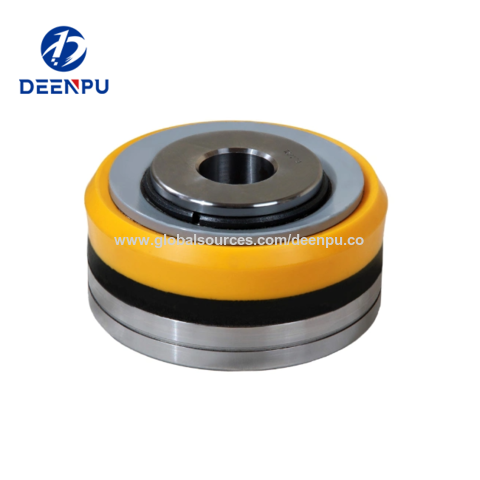
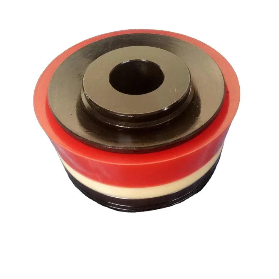
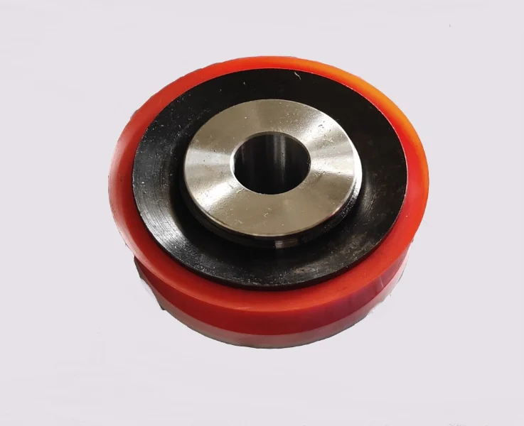
3). The hub is formed from high grade steel. The piston rubber is made from specially formulated compounds which are resistant to the effects of heat,oil and water.
4). The multi-ply fabric reinforced backings used in the production of the piston rubbers provide positive, wear resistant seals. High tensile strength, resistance to chemicals, hydrocarbic.
The piston assembly was made of forging steel 45# or 55 Mn,and piston rubber was made of import high molecular materials. In order to meet the demands of different petroleum drilling technology, we have studied and developed the new model piston assembly with good properties of high-temperature,high-pressure resistance, high anti-friction.
We also produce other kinds of mud pump parts such as Crosshead, Crosshead pin, Crosshead extension rod, Cylinder cover, Cylinder cover flange, Cylinder liner flange, Cylinder head plug, Liner wear ring, Discharge filter screen, Piston draw rod, End cover, Stuffing box, Clamp assembly, Ejector, Spacer, Guide plate, Valve cover, Crankshaft, Pinion shaft, JA-3 Relief Valve, etc.
1). Technical Support and ProductionAbility: Although we are one relatively new company, but we have the most professional engineers with tens of years experience in mud pump. And we have hundreds of highly skilled workers working on the pump parts and pump assembling with numerous advanced machines. Our production ability has been siteaudited by supervising inspectorate like France BV (Bureau Veritas), DNV(Det Norske Veritas) and SGS-CSTC(Standards Technical Services Co., Ltd.)
2). Quality Assurance: Ten professional inspectors performstrict quality inspection from the initial forgings, castings, other rawmaterials, each finished machined parts until the final assembling of the pump. Each part assembled on the pump will be well tested and highly qualified. Andfor each pump finished, it will be running tested in our test center for atleast 4 hours. Quality certificate, Inspection report and testing report will beattached when pump is delivered. 12 Months quality guarantee will be offered for each pump.
3). Competitive Price: We are one of the top pump manufacturers in China. We have the greatest advantages in price. We can not offer you the lowest price in China, but most competitive price but with very good quality.
4). Quick Delivery: Usually we will keep some pump model in stock so that we can make fast delivery for clients with urgent need. For pump we do not have in stock, we can also deliver with 40 days.

As usual, winter — or the slow season — is the time most drillers take the time to maintain their equipment in order to get ready for the peak season. One of the main parts that usually needs attention is the mud pump. Sometimes, it is just a set of swabs to bring it up to snuff, but often, tearing it down and inspecting the parts may reveal that other things need attention. For instance, liners. I can usually run three sets of swabs before it is time to change the liner. New liners and swabs last a good long time. The second set of swabs lasts less, and by the time you put in your third set of swabs, it’s time to order new liners. Probably rods too. It’s not always necessary to change pistons when you change swabs. Sometimes just the rubber needs to be changed, saving money. How do you tell? There is a small groove around the outside of the piston. As it wears, the groove will disappear and it’s time for a new piston.
The wear groove on a piston can be a good indicator of the general health of your pump. If the wear is pretty even all around, chances are the pump is in pretty good shape. But if you see wear on one side only, that is a clue to dig deeper. Uneven wear is a sign that the rods are not stroking at the exact angle that they were designed to, which is parallel to the liner. So, it’s time to look at the gear end. Or as some folks call it, “the expensive end.”
The wear groove on a piston can be a good indicator of the general health of your pump. If the wear is pretty even all around, chances are the pump is in pretty good shape. But if you see wear on one side only, that is a clue to dig deeper.
After you get the cover off the gear end, the first thing to look at will be the oil. It needs to be fairly clean, with no drill mud in it. Also look for metal. Some brass is to be expected, but if you put a magnet in the oil and come back later and it has more than a little metal on it, it gets more serious. The brass in the big end of the connecting rod is a wearable part. It is made to be replaced at intervals — usually years. The most common source of metal is from the bull and pinion gears. They transmit the power to the mud. If you look at the pinion gear closely, you will find that it wears faster than the bull gear. This is for two reasons. First, it is at the top of the pump and may not receive adequate lubrication. The second reason is wear. All the teeth on both the bull and pinion gears receive the same amount of wear, but the bull gear has many more teeth to spread the wear. That is why, with a well maintained pump, the bull gear will outlast the pinion gear three, four or even five times. Pinion gears aren’t too expensive and are fairly easy to change.
This process is fairly straightforward machine work, but over the years, I have discovered a trick that will bring a rebuild up to “better than new.” When you tear a pump down, did you ever notice that there is about 1-inch of liner on each end that has no wear? This is because the swab never gets to it. If it has wear closer to one end than the other, your rods are out of adjustment. The trick is to offset grind the journals. I usually offset mine about ¼-inch. This gives me a ½-inch increase in the stroke without weakening the gear end. This turns a 5x6 pump into a 5½x6 pump. More fluid equals better holes. I adjust the rods to the right length to keep from running out the end of the liner, and enjoy the benefits.
Other than age, the problem I have seen with journal wear is improper lubrication. Smaller pumps rely on splash lubrication. This means that as the crank strokes, the rods pick up oil and it lubricates the crank journals. If your gear end is full of drill mud due to bad packing, it’s going to eat your pump. If the oil is clean, but still shows crank wear, you need to look at the oil you are using.
Oil that is too thick will not be very well picked up and won’t find its way into the oil holes in the brass to lubricate the journals. I’ve seen drillers that, when their pump starts knocking, they switch to a heavier weight oil. This actually makes the problem worse. In my experience, factory specified gear end oil is designed for warmer climates. As you move north, it needs to be lighter to do its job. Several drillers I know in the Northern Tier and Canada run 30 weight in their pumps. In Georgia, I run 40W90. Seems to work well.

Mystique Mud pump Coolant and Lubricant extends mud pump liner and piston life and provides internal lubrication and extra cooling to the coolant system of mud pumps. It extends the life of all liners, even ceramic. Mystique will not cause corrosion or rusting of iron, and is safe with all alloys. Recommened dilution rate of 12.5%. (25 gallons will treat a 200-gallon system.) For use on closed systems.
Mechanical pumps serve in a wide range of applications such as pumping water from wells, aquarium filtering, pond filtering and aeration, in the car industry for water-cooling and fuel injection, in the energy industry for pumping oil and natural gas or for operating cooling towers and other components of heating, ventilation and air conditioning systems. In the medical industry, pumps are used for biochemical processes in developing and manufacturing medicine, and as artificial replacements for body parts, in particular the artificial heart and penile prosthesis.
When a pump contains two or more pump mechanisms with fluid being directed to flow through them in series, it is called a multi-stage pump. Terms such as two-stage or double-stage may be used to specifically describe the number of stages. A pump that does not fit this description is simply a single-stage pump in contrast.
In biology, many different types of chemical and biomechanical pumps have evolved; biomimicry is sometimes used in developing new types of mechanical pumps.
Pumps can be classified by their method of displacement into positive-displacement pumps, impulse pumps, velocity pumps, gravity pumps, steam pumps and valveless pumps. There are three basic types of pumps: positive-displacement, centrifugal and axial-flow pumps. In centrifugal pumps the direction of flow of the fluid changes by ninety degrees as it flows over an impeller, while in axial flow pumps the direction of flow is unchanged.
Some positive-displacement pumps use an expanding cavity on the suction side and a decreasing cavity on the discharge side. Liquid flows into the pump as the cavity on the suction side expands and the liquid flows out of the discharge as the cavity collapses. The volume is constant through each cycle of operation.
Positive-displacement pumps, unlike centrifugal, can theoretically produce the same flow at a given speed (rpm) no matter what the discharge pressure. Thus, positive-displacement pumps are constant flow machines. However, a slight increase in internal leakage as the pressure increases prevents a truly constant flow rate.
A positive-displacement pump must not operate against a closed valve on the discharge side of the pump, because it has no shutoff head like centrifugal pumps. A positive-displacement pump operating against a closed discharge valve continues to produce flow and the pressure in the discharge line increases until the line bursts, the pump is severely damaged, or both.
A relief or safety valve on the discharge side of the positive-displacement pump is therefore necessary. The relief valve can be internal or external. The pump manufacturer normally has the option to supply internal relief or safety valves. The internal valve is usually used only as a safety precaution. An external relief valve in the discharge line, with a return line back to the suction line or supply tank provides increased safety.
Rotary-type positive displacement: internal or external gear pump, screw pump, lobe pump, shuttle block, flexible vane or sliding vane, circumferential piston, flexible impeller, helical twisted roots (e.g. the Wendelkolben pump) or liquid-ring pumps
Drawbacks: The nature of the pump requires very close clearances between the rotating pump and the outer edge, making it rotate at a slow, steady speed. If rotary pumps are operated at high speeds, the fluids cause erosion, which eventually causes enlarged clearances that liquid can pass through, which reduces efficiency.
Hollow disk pumps (also known as eccentric disc pumps or Hollow rotary disc pumps), similar to scroll compressors, these have a cylindrical rotor encased in a circular housing. As the rotor orbits and rotates to some degree, it traps fluid between the rotor and the casing, drawing the fluid through the pump. It is used for highly viscous fluids like petroleum-derived products, and it can also support high pressures of up to 290 psi.
Vibratory pumps or vibration pumps are similar to linear compressors, having the same operating principle. They work by using a spring-loaded piston with an electromagnet connected to AC current through a diode. The spring-loaded piston is the only moving part, and it is placed in the center of the electromagnet. During the positive cycle of the AC current, the diode allows energy to pass through the electromagnet, generating a magnetic field that moves the piston backwards, compressing the spring, and generating suction. During the negative cycle of the AC current, the diode blocks current flow to the electromagnet, letting the spring uncompress, moving the piston forward, and pumping the fluid and generating pressure, like a reciprocating pump. Due to its low cost, it is widely used in inexpensive espresso machines. However, vibratory pumps cannot be operated for more than one minute, as they generate large amounts of heat. Linear compressors do not have this problem, as they can be cooled by the working fluid (which is often a refrigerant).
Reciprocating pumps move the fluid using one or more oscillating pistons, plungers, or membranes (diaphragms), while valves restrict fluid motion to the desired direction. In order for suction to take place, the pump must first pull the plunger in an outward motion to decrease pressure in the chamber. Once the plunger pushes back, it will increase the chamber pressure and the inward pressure of the plunger will then open the discharge valve and release the fluid into the delivery pipe at constant flow rate and increased pressure.
Pumps in this category range from simplex, with one cylinder, to in some cases quad (four) cylinders, or more. Many reciprocating-type pumps are duplex (two) or triplex (three) cylinder. They can be either single-acting with suction during one direction of piston motion and discharge on the other, or double-acting with suction and discharge in both directions. The pumps can be powered manually, by air or steam, or by a belt driven by an engine. This type of pump was used extensively in the 19th century—in the early days of steam propulsion—as boiler feed water pumps. Now reciprocating pumps typically pump highly viscous fluids like concrete and heavy oils, and serve in special applications that demand low flow rates against high resistance. Reciprocating hand pumps were widely used to pump water from wells. Common bicycle pumps and foot pumps for inflation use reciprocating action.
These positive-displacement pumps have an expanding cavity on the suction side and a decreasing cavity on the discharge side. Liquid flows into the pumps as the cavity on the suction side expands and the liquid flows out of the discharge as the cavity collapses. The volume is constant given each cycle of operation and the pump"s volumetric efficiency can be achieved through routine maintenance and inspection of its valves.
This is the simplest form of rotary positive-displacement pumps. It consists of two meshed gears that rotate in a closely fitted casing. The tooth spaces trap fluid and force it around the outer periphery. The fluid does not travel back on the meshed part, because the teeth mesh closely in the center. Gear pumps see wide use in car engine oil pumps and in various hydraulic power packs.
A screw pump is a more complicated type of rotary pump that uses two or three screws with opposing thread — e.g., one screw turns clockwise and the other counterclockwise. The screws are mounted on parallel shafts that have gears that mesh so the shafts turn together and everything stays in place. The screws turn on the shafts and drive fluid through the pump. As with other forms of rotary pumps, the clearance between moving parts and the pump"s casing is minimal.
Widely used for pumping difficult materials, such as sewage sludge contaminated with large particles, a progressing cavity pump consists of a helical rotor, about ten times as long as its width. This can be visualized as a central core of diameter x with, typically, a curved spiral wound around of thickness half x, though in reality it is manufactured in a single casting. This shaft fits inside a heavy-duty rubber sleeve, of wall thickness also typically x. As the shaft rotates, the rotor gradually forces fluid up the rubber sleeve. Such pumps can develop very high pressure at low volumes.
Named after the Roots brothers who invented it, this lobe pump displaces the fluid trapped between two long helical rotors, each fitted into the other when perpendicular at 90°, rotating inside a triangular shaped sealing line configuration, both at the point of suction and at the point of discharge. This design produces a continuous flow with equal volume and no vortex. It can work at low pulsation rates, and offers gentle performance that some applications require.
A peristaltic pump is a type of positive-displacement pump. It contains fluid within a flexible tube fitted inside a circular pump casing (though linear peristaltic pumps have been made). A number of rollers, shoes, or wipers attached to a rotor compresses the flexible tube. As the rotor turns, the part of the tube under compression closes (or occludes), forcing the fluid through the tube. Additionally, when the tube opens to its natural state after the passing of the cam it draws (restitution) fluid into the pump. This process is called peristalsis and is used in many biological systems such as the gastrointestinal tract.
Efficiency and common problems: With only one cylinder in plunger pumps, the fluid flow varies between maximum flow when the plunger moves through the middle positions, and zero flow when the plunger is at the end positions. A lot of energy is wasted when the fluid is accelerated in the piping system. Vibration and
Triplex plunger pumps use three plungers, which reduces the pulsation of single reciprocating plunger pumps. Adding a pulsation dampener on the pump outlet can further smooth the pump ripple, or ripple graph of a pump transducer. The dynamic relationship of the high-pressure fluid and plunger generally requires high-quality plunger seals. Plunger pumps with a larger number of plungers have the benefit of increased flow, or smoother flow without a pulsation damper. The increase in moving parts and crankshaft load is one drawback.
Car washes often use these triplex-style plunger pumps (perhaps without pulsation dampers). In 1968, William Bruggeman reduced the size of the triplex pump and increased the lifespan so that car washes could use equipment with smaller footprints. Durable high-pressure seals, low-pressure seals and oil seals, hardened crankshafts, hardened connecting rods, thick ceramic plungers and heavier duty ball and roller bearings improve reliability in triplex pumps. Triplex pumps now are in a myriad of markets across the world.
Triplex pumps with shorter lifetimes are commonplace to the home user. A person who uses a home pressure washer for 10 hours a year may be satisfied with a pump that lasts 100 hours between rebuilds. Industrial-grade or continuous duty triplex pumps on the other end of the quality spectrum may run for as much as 2,080 hours a year.
The oil and gas drilling industry uses massive semi trailer-transported triplex pumps called mud pumps to pump drilling mud, which cools the drill bit and carries the cuttings back to the surface.
One modern application of positive-displacement pumps is compressed-air-powered double-diaphragm pumps. Run on compressed air, these pumps are intrinsically safe by design, although all manufacturers offer ATEX certified models to comply with industry regulation. These pumps are relatively inexpensive and can perform a wide variety of duties, from pumping water out of bunds to pumping hydrochloric acid from secure storage (dependent on how the pump is manufactured – elastomers / body construction). These double-diaphragm pumps can handle viscous fluids and abrasive materials with a gentle pumping process ideal for transporting shear-sensitive media.
Devised in China as chain pumps over 1000 years ago, these pumps can be made from very simple materials: A rope, a wheel and a pipe are sufficient to make a simple rope pump. Rope pump efficiency has been studied by grassroots organizations and the techniques for making and running them have been continuously improved.
Impulse pumps use pressure created by gas (usually air). In some impulse pumps the gas trapped in the liquid (usually water), is released and accumulated somewhere in the pump, creating a pressure that can push part of the liquid upwards.
Instead of a gas accumulation and releasing cycle, the pressure can be created by burning of hydrocarbons. Such combustion driven pumps directly transmit the impulse from a combustion event through the actuation membrane to the pump fluid. In order to allow this direct transmission, the pump needs to be almost entirely made of an elastomer (e.g. silicone rubber). Hence, the combustion causes the membrane to expand and thereby pumps the fluid out of the adjacent pumping chamber. The first combustion-driven soft pump was developed by ETH Zurich.
It takes in water at relatively low pressure and high flow-rate and outputs water at a higher hydraulic-head and lower flow-rate. The device uses the water hammer effect to develop pressure that lifts a portion of the input water that powers the pump to a point higher than where the water started.
The hydraulic ram is sometimes used in remote areas, where there is both a source of low-head hydropower, and a need for pumping water to a destination higher in elevation than the source. In this situation, the ram is often useful, since it requires no outside source of power other than the kinetic energy of flowing water.
Rotodynamic pumps (or dynamic pumps) are a type of velocity pump in which kinetic energy is added to the fluid by increasing the flow velocity. This increase in energy is converted to a gain in potential energy (pressure) when the velocity is reduced prior to or as the flow exits the pump into the discharge pipe. This conversion of kinetic energy to pressure is explained by the
A practical difference between dynamic and positive-displacement pumps is how they operate under closed valve conditions. Positive-displacement pumps physically displace fluid, so closing a valve downstream of a positive-displacement pump produces a continual pressure build up that can cause mechanical failure of pipeline or pump. Dynamic pumps differ in that they can be safely operated under closed valve conditions (for short periods of time).
Such a pump is also referred to as a centrifugal pump. The fluid enters along the axis or center, is accelerated by the impeller and exits at right angles to the shaft (radially); an example is the centrifugal fan, which is commonly used to implement a vacuum cleaner. Another type of radial-flow pump is a vortex pump. The liquid in them moves in tangential direction around the working wheel. The conversion from the mechanical energy of motor into the potential energy of flow comes by means of multiple whirls, which are excited by the impeller in the working channel of the pump. Generally, a radial-flow pump operates at higher pressures and lower flow rates than an axial- or a mixed-flow pump.
These are also referred to as All fluid pumps. The fluid is pushed outward or inward to move fluid axially. They operate at much lower pressures and higher flow rates than radial-flow (centrifugal) pumps. Axial-flow pumps cannot be run up to speed without special precaution. If at a low flow rate, the total head rise and high torque associated with this pipe would mean that the starting torque would have to become a function of acceleration for the whole mass of liquid in the pipe system. If there is a large amount of fluid in the system, accelerate the pump slowly.
Mixed-flow pumps function as a compromise between radial and axial-flow pumps. The fluid experiences both radial acceleration and lift and exits the impeller somewhere between 0 and 90 degrees from the axial direction. As a consequence mixed-flow pumps operate at higher pressures than axial-flow pumps while delivering higher discharges than radial-flow pumps. The exit angle of the flow dictates the pressure head-discharge characteristic in relation to radial and mixed-flow.
Regenerative turbine pump rotor and housing, 1⁄3 horsepower (0.25 kW). 85 millimetres (3.3 in) diameter impeller rotates counter-clockwise. Left: inlet, right: outlet. .4 millimetres (0.016 in) thick vanes on 4 millimetres (0.16 in) centers
Also known as drag, friction, peripheral, traction, turbulence, or vortex pumps, regenerative turbine pumps are class of rotodynamic pump that operates at high head pressures, typically 4–20 bars (4.1–20.4 kgf/cm2; 58–290 psi).
The pump has an impeller with a number of vanes or paddles which spins in a cavity. The suction port and pressure ports are located at the perimeter of the cavity and are isolated by a barrier called a stripper, which allows only the tip channel (fluid between the blades) to recirculate, and forces any fluid in the side channel (fluid in the cavity outside of the blades) through the pressure port. In a regenerative turbine pump, as fluid spirals repeatedly from a vane into the side channel and back to the next vane, kinetic energy is imparted to the periphery,
As regenerative turbine pumps cannot become vapor locked, they are commonly applied to volatile, hot, or cryogenic fluid transport. However, as tolerances are typically tight, they are vulnerable to solids or particles causing jamming or rapid wear. Efficiency is typically low, and pressure and power consumption typically decrease with flow. Additionally, pumping direction can be reversed by reversing direction of spin.
Steam pumps have been for a long time mainly of historical interest. They include any type of pump powered by a steam engine and also pistonless pumps such as Thomas Savery"s or the Pulsometer steam pump.
Recently there has been a resurgence of interest in low power solar steam pumps for use in smallholder irrigation in developing countries. Previously small steam engines have not been viable because of escalating inefficiencies as vapour engines decrease in size. However the use of modern engineering materials coupled with alternative engine configurations has meant that these types of system are now a cost-effective opportunity.
Valveless pumping assists in fluid transport in various biomedical and engineering systems. In a valveless pumping system, no valves (or physical occlusions) are present to regulate the flow direction. The fluid pumping efficiency of a valveless system, however, is not necessarily lower than that having valves. In fact, many fluid-dynamical systems in nature and engineering more or less rely upon valveless pumping to transport the working fluids therein. For instance, blood circulation in the cardiovascular system is maintained to some extent even when the heart"s valves fail. Meanwhile, the embryonic vertebrate heart begins pumping blood long before the development of discernible chambers and valves. Similar to blood circulation in one direction, bird respiratory systems pump air in one direction in rigid lungs, but without any physiological valve. In microfluidics, valveless impedance pumps have been fabricated, and are expected to be particularly suitable for handling sensitive biofluids. Ink jet printers operating on the piezoelectric transducer principle also use valveless pumping. The pump chamber is emptied through the printing jet due to reduced flow impedance in that direction and refilled by capillary action.
Examining pump repair records and mean time between failures (MTBF) is of great importance to responsible and conscientious pump users. In view of that fact, the preface to the 2006 Pump User"s Handbook alludes to "pump failure" statistics. For the sake of convenience, these failure statistics often are translated into MTBF (in this case, installed life before failure).
In early 2005, Gordon Buck, John Crane Inc.’s chief engineer for field operations in Baton Rouge, Louisiana, examined the repair records for a number of refinery and chemical plants to obtain meaningful reliability data for centrifugal pumps. A total of 15 operating plants having nearly 15,000 pumps were included in the survey. The smallest of these plants had about 100 pumps; several plants had over 2000. All facilities were located in the United States. In addition, considered as "new", others as "renewed" and still others as "established". Many of these plants—but not all—had an alliance arrangement with John Crane. In some cases, the alliance contract included having a John Crane Inc. technician or engineer on-site to coordinate various aspects of the program.
Not all plants are refineries, however, and different results occur elsewhere. In chemical plants, pumps have historically been "throw-away" items as chemical attack limits life. Things have improved in recent years, but the somewhat restricted space available in "old" DIN and ASME-standardized stuffing boxes places limits on the type of seal that fits. Unless the pump user upgrades the seal chamber, the pump only accommodates more compact and simple versions. Without this upgrading, lifetimes in chemical installations are generally around 50 to 60 percent of the refinery values.
Unscheduled maintenance is often one of the most significant costs of ownership, and failures of mechanical seals and bearings are among the major causes. Keep in mind the potential value of selecting pumps that cost more initially, but last much longer between repairs. The MTBF of a better pump may be one to four years longer than that of its non-upgraded counterpart. Consider that published average values of avoided pump failures range from US$2600 to US$12,000. This does not include lost opportunity costs. One pump fire occurs per 1000 failures. Having fewer pump failures means having fewer destructive pump fires.
As has been noted, a typical pump failure, based on actual year 2002 reports, costs US$5,000 on average. This includes costs for material, parts, labor and overhead. Extending a pump"s MTBF from 12 to 18 months would save US$1,667 per year — which might be greater than the cost to upgrade the centrifugal pump"s reliability.
Pumps are used throughout society for a variety of purposes. Early applications includes the use of the windmill or watermill to pump water. Today, the pump is used for irrigation, water supply, gasoline supply, air conditioning systems, refrigeration (usually called a compressor), chemical movement, sewage movement, flood control, marine services, etc.
Because of the wide variety of applications, pumps have a plethora of shapes and sizes: from very large to very small, from handling gas to handling liquid, from high pressure to low pressure, and from high volume to low volume.
Typically, a liquid pump can"t simply draw air. The feed line of the pump and the internal body surrounding the pumping mechanism must first be filled with the liquid that requires pumping: An operator must introduce liquid into the system to initiate the pumping. This is called priming the pump. Loss of prime is usually due to ingestion of air into the pump. The clearances and displacement ratios in pumps for liquids, whether thin or more viscous, usually cannot displace air due to its compressibility. This is the case with most velocity (rotodynamic) pumps — for example, centrifugal pumps. For such pumps, the position of the pump should always be lower than the suction point, if not the pump should be manually filled with liquid or a secondary pump should be used until all air is removed from the suction line and the pump casing.
Positive–displacement pumps, however, tend to have sufficiently tight sealing between the moving parts and the casing or housing of the pump that they can be described as self-priming. Such pumps can also serve as priming pumps, so-called when they are used to fulfill that need for other pumps in lieu of action taken by a human operator.
One sort of pump once common worldwide was a hand-powered water pump, or "pitcher pump". It was commonly installed over community water wells in the days before piped water supplies.
In parts of the British Isles, it was often called the parish pump. Though such community pumps are no longer common, people still used the expression parish pump to describe a place or forum where matters of local interest are discussed.
Because water from pitcher pumps is drawn directly from the soil, it is more prone to contamination. If such water is not filtered and purified, consumption of it might lead to gastrointestinal or other water-borne diseases. A notorious case is the 1854 Broad Street cholera outbreak. At the time it was not known how cholera was transmitted, but physician John Snow suspected contaminated water and had the handle of the public pump he suspected removed; the outbreak then subsided.
Modern hand-operated community pumps are considered the most sustainable low-cost option for safe water supply in resource-poor settings, often in rural areas in developing countries. A hand pump opens access to deeper groundwater that is often not polluted and also improves the safety of a well by protecting the water source from contaminated buckets. Pumps such as the Afridev pump are designed to be cheap to build and install, and easy to maintain with simple parts. However, scarcity of spare parts for these type of pumps in some regions of Africa has diminished their utility for these areas.
Multiphase pumping applications, also referred to as tri-phase, have grown due to increased oil drilling activity. In addition, the economics of multiphase production is attractive to upstream operations as it leads to simpler, smaller in-field installations, reduced equipment costs and improved production rates. In essence, the multiphase pump can accommodate all fluid stream properties with one piece of equipment, which has a smaller footprint. Often, two smaller multiphase pumps are installed in series rather than having just one massive pump.
A rotodynamic pump with one single shaft that requires two mechanical seals, this pump uses an open-type axial impeller. It is often called a Poseidon pump, and can be described as a cross between an axial compressor and a centrifugal pump.
The twin-screw pump is constructed of two inter-meshing screws that move the pumped fluid. Twin screw pumps are often used when pumping conditions contain high gas volume fractions and fluctuating inlet conditions. Four mechanical seals are required to seal the two shafts.
These pumps are basically multistage centrifugal pumps and are widely used in oil well applications as a method for artificial lift. These pumps are usually specified when the pumped fluid is mainly liquid.
A buffer tank is often installed upstream of the pump suction nozzle in case of a slug flow. The buffer tank breaks the energy of the liquid slug, smooths any fluctuations in the incoming flow and acts as a sand trap.
As the name indicates, multiphase pumps and their mechanical seals can encounter a large variation in service conditions such as changing process fluid composition, temperature variations, high and low operating pressures and exposure to abrasive/erosive media. The challenge is selecting the appropriate mechanical seal arrangement and support system to ensure maximized seal life and its overall effectiveness.
Pumps are commonly rated by horsepower, volumetric flow rate, outlet pressure in metres (or feet) of head, inlet suction in suction feet (or metres) of head.
From an initial design point of view, engineers often use a quantity termed the specific speed to identify the most suitable pump type for a particular combination of flow rate and head.
The power imparted into a fluid increases the energy of the fluid per unit volume. Thus the power relationship is between the conversion of the mechanical energy of the pump mechanism and the fluid elements within the pump. In general, this is governed by a series of simultaneous differential equations, known as the Navier–Stokes equations. However a more simple equation relating only the different energies in the fluid, known as Bernoulli"s equation can be used. Hence the power, P, required by the pump:
where Δp is the change in total pressure between the inlet and outlet (in Pa), and Q, the volume flow-rate of the fluid is given in m3/s. The total pressure may have gravitational, static pressure and kinetic energy components; i.e. energy is distributed between change in the fluid"s gravitational potential energy (going up or down hill), change in velocity, or change in static pressure. η is the pump efficiency, and may be given by the manufacturer"s information, such as in the form of a pump curve, and is typically derived from either fluid dynamics simulation (i.e. solutions to the Navier–Stokes for the particular pump geometry), or by testing. The efficiency of the pump depends upon the pump"s configuration and operating conditions (such as rotational speed, fluid density and viscosity etc.)
For a typical "pumping" configuration, the work is imparted on the fluid, and is thus positive. For the fluid imparting the work on the pump (i.e. a turbine), the work is negative. Power required to drive the pump is determined by dividing the output power by the pump efficiency. Furthermore, this definition encompasses pumps with no moving parts, such as a siphon.
Pump efficiency is defined as the ratio of the power imparted on the fluid by the pump in relation to the power supplied to drive the pump. Its value is not fixed for a given pump, efficiency is a function of the discharge and therefore also operating head. For centrifugal pumps, the efficiency tends to increase with flow rate up to a point midway through the operating range (peak efficiency or Best Efficiency Point (BEP) ) and then declines as flow rates rise further. Pump performance data such as this is usually supplied by the manufacturer before pump selection. Pump efficiencies tend to decline over time due to wear (e.g. increasing clearances as impellers reduce in size).
When a system includes a centrifugal pump, an important design issue is matching the head loss-flow characteristic with the pump so that it operates at or close to the point of its maximum efficiency.
Most large pumps have a minimum flow requirement below which the pump may be damaged by overheating, impeller wear, vibration, seal failure, drive shaft damage or poor performance.
The simplest minimum flow system is a pipe running from the pump discharge line back to the suction line. This line is fitted with an orifice plate sized to allow the pump minimum flow to pass.
A more sophisticated, but more costly, system (see diagram) comprises a flow measuring device (FE) in the pump discharge which provides a signal into a flow controller (FIC) which actuates a flow control valve (FCV) in the recycle line. If the measured flow exceeds the minimum flow then the FCV is closed. If the measured flow falls below the minimum flow the FCV opens to maintain the minimum flowrate.
As the fluids are recycled the kinetic energy of the pump increases the temperature of the fluid. For many pumps this added heat energy is dissipated through the pipework. However, for large industrial pumps, such as oil pipeline pumps, a recycle cooler is provided in the recycle line to cool the fluids to the normal suction temperature.oil refinery, oil terminal, or offshore installation.
Engineering Sciences Data Unit (2007). "Radial, mixed and axial flow pumps. Introduction" (PDF). Archived from the original (PDF) on 2014-03-08. Retrieved 2017-08-18.
Tanzania water Archived 2012-03-31 at the Wayback Machine blog – example of grassroots researcher telling about his study and work with the rope pump in Africa.
C.M. Schumacher, M. Loepfe, R. Fuhrer, R.N. Grass, and W.J. Stark, "3D printed lost-wax casted soft silicone monoblocks enable heart-inspired pumping by internal combustion," RSC Advances, Vol. 4, pp. 16039–16042, 2014.
"Radial, mixed and axial flow pumps" (PDF). Institution of Diploma Marine Engineers, Bangladesh. June 2003. Archived from the original (PDF) on 2014-03-08. Retrieved 2017-08-18.
Quail F, Scanlon T, Stickland M (2011-01-11). "Design optimisation of a regenerative pump using numerical and experimental techniques" (PDF). International Journal of Numerical Methods for Heat & Fluid Flow. 21: 95–111. doi:10.1108/09615531111095094. Retrieved 2021-07-21.
Rajmane, M. Satish; Kallurkar, S.P. (May 2015). "CFD Analysis of Domestic Centrifugal Pump for Performance Enhancement". International Research Journal of Engineering and Technology. 02 / #02. Retrieved 30 April 2021.
Wasser, Goodenberger, Jim and Bob (November 1993). "Extended Life, Zero Emissions Seal for Process Pumps". John Crane Technical Report. Routledge. TRP 28017.
Australian Pump Manufacturers" Association. Australian Pump Technical Handbook, 3rd edition. Canberra: Australian Pump Manufacturers" Association, 1987. ISBN 0-7316-7043-4.

Bonded-Nitrile Pistons . . . . . . . . . . . . . . . . . . . . . . . . . . . . . . . . . . . . . . . . . . . . . . . . . . . . . . . . . . . . . . . . . 9
Replaceable Nitrile Pistons . . . . . . . . . . . . . . . . . . . . . . . . . . . . . . . . . . . . . . . . . . . . . . . . . . . . . . . . . . . . 10
Mud-Pump Gear Sets . . . . . . . . . . . . . . . . . . . . . . . . . . . . . . . . . . . . . . . . . . . . . . . . . . . . . . . . . . . . . . . . . 13


 8613371530291