
mud pump pony rod seal installation factory

Plunger pumps are the workhorse of oil and gas fracking and drilling operations. They circulate high pressure fluid down the well and back up the annulus in both land and off-shore operations. When pumps are offline for planned or unplanned maintenance to replace leaking fluid, or worn seals, your operations stop.
Parker’s patented pony rod seal extends continuous service with a longer lasting, reliable design that retains lubrication and prevents leakage of hydraulic fluid in the power end and also serves as a rod wiper to keep contaminants out.
•High contact force sealing lip design, coupled with compression-set resistant Resilon seal material, retains lubricating oil in the power end, eliminating necessity of shut down to add fluid

In an offshore drilling operation, a drillstring extends from the rig platform into a wellbore whereat its drillbit drills deeper and deeper into the sea floor. During drilling, pumps circulate mud through the drillbit and back through the riser surrounding the drillstring. Mudpumps are usually large positive displacement pumps which generate flow by reciprocal plunger movement. In a triplex mudpump, for example, three plungers can be reciprocally driven by pony rods to suction the working fluid (e.g., mud slurry) through an inlet and discharge it through an outlet. A typical triplex mudpump could have a horsepower rating from 275 to 2000 BHP and discharge pressures from 1000 psi to 7500 psi. In offshore drilling, as well as many other industrial situations, convenient accessibility of expendable parts, such as reciprocating-rod seals, can be of the utmost importance.
A seal comprises a one-piece rigid support and a one-piece elastomeric body bonded to the rigid support. The rigid support encases the elastomeric body whereby it does not extend radially or axially beyond a retaining wall. The elastomeric body forms a sealing lip that prevents fluid escape during forward and return strokes of the reciprocating rod. The elastomeric body also forms a wiping lip, that removes dirt, dust and other debris from the rod during return strokes.
In a mudpump, for example, the seal can be used to seal interfaces associated with pony rods or plunger rods. In such a mudpump application, the seal will be easily accessible for installation, inspection or replacement. Furthermore, in many mudpump situations, the seal can be the only sealing component necessary on the reciprocating rod. In other words, the seal can be the primary seal on a mudpump reciprocating rod assembly, without buffer rings and/or stronger seals within the housing.
These and other features of the seal are fully described and particularly pointed out in the claims. The following description and annexed drawings set forth in detail certain illustrative embodiments, these embodiments being indicative of but a few of the various ways in which the principles may be employed.
FIG. 1 is a cross-sectional view of a reciprocating-rod seal in a pre-installation condition, the seal including a rigid support and an elastomeric body.
A reciprocating-rod seal 10 is shown in FIG. 1 in a pre-installation condition. The seal 10 has an inner-radial surface 11, an outer-radial surface 12, a fluidside surface 13, and an airside surface 14. The distance between the radial surfaces 11 and 12 can be considered the radial thickness of the seal 10 and the distance between the side surfaces 13 and 14 can be considered its axial length.
The seal 10 comprises a rigid support 20 and an elastomeric body 30 bonded thereto. The support-body bond, and its ability to withstand heat, pressure, and repeated reciprocal motion, may factor heavily into the life and the performance of the seal 10. Thus materials and bonding techniques may be chosen to optimize the adherence between the support 20 and the elastomeric body 30. For example, the rigid support 20 can be made of stainless steel, the elastomeric body 30 can be made of polyurethane, and bonding can be accomplished during injection molding.
The cylindrical retaining wall 22 forms the seal"s outer-radial surface 12 and, in the illustrated embodiment, the elastomeric body 30 does not extend axially or radially beyond this wall 22. The flange wall 24 extends radially inward from an airside end of the wall 22. The anchor wall 25 extends axially in the fluidside direction from the inner-radial end of the flange wall 24. The wall-to-wall transitions (i.e., the corners) can be rounded, curved, sharp, blunt or another profile compatible with the expected sealing application and intended manufacturing method.
The span of the flange wall 24 can be between 20% and 50% of the radial thickness of the seal 10, and the reach of the anchor wall 25 can be between 10% and 30% of the seal"s axial length. The flange wall 24 partially forms the airside surface 14 of the seal 10 and the anchor wall 25 is embedded within the elastomeric body 30. The walls" span/reach may depend, at least somewhat, upon the geometry of a groove (namely a groove 50, introduced below), in the elastomeric body 30.
The gauge of the walls 22, 24, 25 of the rigid support 20 can be relatively small compared to the overall radial thickness of the seal 10. For example, the wall gauge will usually be in the range of 1 mm to 5 mm and/or 5% to 20% the radial thickness of the seal 10. If the support 20 is stamped or otherwise formed from sheet material, the gauges of the walls 22, 24, 25 will be approximately equal.
The fluid-side edge section 26 of the retaining wall 22 (e.g., 10% to 30% of the wall"s axial length) can be thinner than the rest of the retaining wall. For example, the edge section 26 can be crimped or otherwise made thinner than the rest of the wall 22. This geometry may prove helpful, in that it can provide a predetermined bending area during support/seal insertion during installation and/or manufacture. The same could be accomplished by, for example, notching, perforating, or otherwise weakening the proximal region of the edge section 26 to form a living hinge.
The elastomeric body has an inner-radial face 31, an outer-radial face 32, a fluidside face 33, and an airside face 34. The outer-radial face 32 is encased by the cylindrical retaining wall 22 whereby, as mentioned above, the elastomeric body 30 does not extend axially or radially beyond this wall 22. The inner-radial face 31 forms the seal"s inner-radial surface 11, and can include a fluidside ramp 35, an airside ramp 36, and a shallow 37 therebetween.
The fluidside face 33 forms the seal"s fluidside surface 13. A notch 40 in the fluidside face 33 (and/or the seal"s fluidside surface 13) separates the elastomeric body 30 into an ID fluidside portion 41 and an OD fluidside portion 42. The ID fluidside portion forms a sealing lip 43 and can include a cutoff corner 44.
The airside face 34 of the elastomeric body 30 can form the airside surface 14 of the seal 10 along with the flange wall 24 of the rigid support 20. A groove 50 in the airside face 34 (and/or the seal"s airside surface 14) separates the elastomeric body 30 into an ID airside portion 51 and an OD airside portion 52. The ID airside portion 51 forms a wiping lip 53 and can include an acute corner 54. The flange wall 24 of the rigid support 20 encases part of the OD airside portion 52 and the anchor wall 25 is embedded therein. The groove 50 can also include a rim 55 around its airside edge.
In the illustrated seal 10, the notch 40 has a cross-sectional shape resembling a rounded-vertex V. And the groove 50 has a cross-sectional shape resembling a rimmed U. While such geometries will be suitable in many applications, the shape, size, and/or situating of the notch 40 and/or the groove 50 can be varied to best provide the desired sealing and wiping functions, to facilitate installation, and/or to simplify manufacture.
For example, the size, shape, and situating of the notch/groove can be selected to accommodate installation. As is explained in more detail below, the seal 10 is radially compressed during installation, and this installation compression will usually be concentrated in the ID portions 41 and 51 of the elastomeric body 30. In many seal constructions, the thicker the ID portions 42/52, the greater the compression required for seal installation. Thus, the notch/groove can be designed to insure that the required forces are reasonable for the intended seal application.
The size/shape/situating of the notch 40 and the groove 50 should also be selected to insure that the lips 43/53 can maintain constant sliding contact with the relevant reciprocating rod. In most instances, the sealing lip 43 should probably apply a greater rod-contact force than the wiping lip 53. Otherwise, the wiping lip 53 could block fluid film still on the reciprocating rod (e.g., fluid that snuck past the sealing lip 43) during forward strokes, resulting in fluid accumulation within the shallow 37, and eventual leakage therefrom. This desired rod-contact-force relationship can be accomplished by, for example, the groove 50 being wider, deeper, and/or closer (to the OD face 32) than the notch 40.
The size, shape, and/or situating of the notch 40 and/or the groove may further take into consideration the integrity of the bond between the rigid support 20 and the elastomeric body 30. For example, if an elastomer is expected to shrink after seal formation, this can cause the elastomeric OD portions 42/52 to pull away (i.e., radially inward) from the rigid retaining wall 22. If so, thinner OD portions 42/52 may be preferred to lesson this pull and thereby preserve bond integrity.
In most intended sealing situations, a notch 40 and/or a groove 50 having a radial span (at its fluidside end) of 10% to 30% of the radial thickness of the seal 10, and a depth (in the axial direction) of about 20% to 40% of the seal"s axial length, will be suitable.
As shown in FIG. 2, the seal 10 can (but need not) further comprise a reinforcement member 60 lining its airside groove 50. The reinforcement member 60 can have a shape corresponding to the non-rimmed regions of the groove 50, and the rim 55 can be helpful in holding reinforcement member 60 in place prior to installation. The member 60 can comprise, for example, a folded metal sheet that functions as spring in the seal 10 and resiliently urges the airside portions 51 and 52 radially away from each other.
A method of making the seal 10 with a mold 70 is schematically shown in FIGS. 3A-3D. The mold 70 has a cavity 71 formed by mold parts 72, 73, and 74. The first mold part 72 has a channel 75 corresponding to the seal"s airside face 14 (and at least some of its OD face 12) and groove-forming projection 76. The second mold part 73 has a channel 77 corresponding to the seal"s fluidside face 13 (and possibly some of its OD face 12) and a notch-forming projection 78. The core part 74 has a perimeter corresponding to the seal"s ID face 11 (e.g., ramp-shallow-ramp).
Once the mold parts 72, 73, and 74 are compiled, an elastomer is introduced (e.g., injected) into the cavity 71. The introduced-elastomer pressure within the cavity 71 pushes the retaining wall 22 against the channel cliff and the flange wall 24 against the channel floor. The rigid retainer 20, and its positioning within the mold cavity 71, can thereby prevent the elastomer from extending axially or radially beyond the cylindrical wall 22.
After the elastomer cures and/or hardens, the mold 70 is opened and the molded piece is removed therefrom. In the illustrated embodiment, the molded piece has an OD fluidside geometry bulging beyond that of the seal 10 and it must be trimmed to form the sealing lip 43. If the molded piece has a geometry more closely mirroring that of the seal 10, such trimming may not be necessary. But one advantage of a method including a trimming step is that the ID parting line (between the upper mold part 73 and the core part 74) can be positioned above the sealing-lip location. In this manner, any ragged-flash seams caused by the parting line are removed during trimming and a smooth sharp sealing lip 43 is formed.
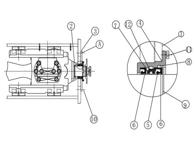
Referring now to FIG. 4, the seal 10 is shown as part of a reciprocating-rod assembly 80 comprising a housing 81 and a rod 82 that reciprocally moves relative to the housing 81. The housing 81 comprises an opening 83 through which the rod 82 extends and a pocket 84 surrounding the opening 83. The pocket 84 has a floor 85 and a ledge 86 extending radially inward from the floor"s fluidside end.
When the seal 10 is installed in the pocket 84, its cylindrical retaining wall 22 abuts against the pocket"s floor 85. If the retaining wall 22 has a hinged end section 26, this may aid in press-fitting the rigid support 20 into the pocket 84 during seal installation. The ledge 86 can preferably project beyond the wall end section 26 so that the OD fluidside portion 42 can lie flush thereagainst.
The radial distance between the pocket floor 85 and the rod 81 is less than the seal"s thickness, and the ID portions 41 and 51 are compressed to fit within this smaller space. The corners 44 and 54 are flattened by this compression and the lips 43 and 53 slidingly contact the rod 81. More specifically, the fluidside ramp region 35 of the ID face 31 forms a rod-contacting region of the sealing lip 43 and the airside ramp region 36 forms a rod-contacting region of the wiping lip 53. The shallow 37 between the ramp regions is not a rod-contacting region. As was explained above, it may be important in many instances that the sealing lip 43 apply a greater contract force against the rod 81 than the wiping lip 53.
In operation of the assembly 80, the rod 82 moves in a reciprocal manner with forward strokes away from the housing 81 and return strokes back towards the housing 81. During forward and return strokes, the sealing lip 43 seals the housing-rod interface and prevents fluid from escaping from the housing 81. During return strokes, the wiping lip 53 removes (e.g., wipes) dirt, dust, and other debris from rod 82.
The reciprocating-rod assembly 80 can be part of a pump, such as the mudpump 90 shown in FIG. 5. The mudpump 90 comprises a power-providing station 91 and a pumping station 92 that work together to suction a working fluid (e.g., mud slurry) through an inlet 93 and discharges it through an outlet 94. The power-providing station 91 houses equipment (e.g., crank shaft, cross-heads, etc.) for reciprocal movement of pony rods 95 that extend through appropriate openings in the front panel 96 of the station"s housing. The pumping station 92 houses a cylinder block for receipt of plungers, carried by plunger rods 97 extending through appropriate openings in a rear panel 98 of the station housing. The pony rods 95 and the plunger rods 97 interconnect between the stations 91 and 92, so that the plunger rods 93 are reciprocally driven by the pony rods 95. If the mudpump 90 has a triplex design, for example, it could have three pony rods 95 and three plunger rods 97.
The reciprocating rod assembly 80, and thus the seal 10, can be used in conjunction with the mudpump pony rods 95 and/or the mudpump plunger rods 97. In either or any case, a station panel 96/97 is the housing 81, a rod 95/97 is the reciprocating rod 82, and the seal 10 is positioned in a pocket 84 around the rod-receiving opening in the housing 81. With the seal 10 so positioned in the mudpump 90, it is easily accessible for installation, inspection or replacement. Furthermore, it can serve as the only seal on the relevant rod 95/97 whereby buffer rings and/or supplemental seals within the housing are not necessary. In other words, the seal 10 can be the primary seal on the mudpump"s reciprocating rod assembly 80.
Although the seal 10, the rigid support 20, the elastomeric body 30, the mold 70, the assembly 80, the mudpump 90, and other related components, elements, methods, and steps, have been shown and described with respect to certain embodiments, it is obvious that equivalent alterations and modifications will occur to others skilled in the art upon the reading and understanding of this specification and the annexed drawings. In regard to the various functions performed by the above described elements (e.g., components, assemblies, systems, steps, devices, compositions, etc.), the terms (including a reference to a “means”) used to describe such elements are intended to correspond, unless otherwise indicated, to any element which performs the specified function of the described element (i.e., that is functionally equivalent), even though not structurally equivalent to the disclosed structure which performs the function. In addition, while a particular feature may have been described above with respect to only one or more of several illustrated embodiments, such feature may be combined with one or more other features of the other embodiments, as may be desired and advantageous for any given or particular application.
Pony rod also called the intermediate rod, is an important part of the connection between the crosshead and the piston rod. It is the key component that connects the power end and the hydraulic end of the mud pump. One end is connected to the crosshead and the other end is connected to the piston rod by a clamp. Its outer circumference is filled with a packing box assembly. In the reciprocating motion, the outer circle of the intermediate tie rod and the sealing member in the packing box rub against each other. To ensure it"s wear resistance, the outer surface of the intermediate rod is hard chrome-plated.
We can offer a wide range of extension (pony) rods for triplex mud pumps that are made of high quality alloy steel (40Cr). After strict heat treatment of quenching and high temperature, the rods have the features of high intensity on surface and high tough inside. The surface is treated with galvanization or nitrogen for high intensity and low abrasion.

Kerr Pumps manufacturers a wide variety of high quality valves and seats. We offer plenty of configurations and materials to choose from such as our more popular salt bath nitrided 17-4 stainless steel. We also keep in stock a full line of Well Service inserted valves and o-ringed seats.
All of our pony rod glands are machined in-house on one of our many CNC lathes. The level of precision and finish in each gland gives an incredible repeatability from part to part. This consistency extends the life of each seal and pony rod which keeps you pumping longer in the field.And Many More!
We believe that making incredible pumps is just part of the game. Our main focus is taking care of our customers. That is why we stock a full line of pump replacement parts. We do our absolute best in meeting customer demands and continue to strive to be the most responsive pump company.

High-contact force sealing lip design coupled with compression set resistant Resilon seal material retains lubricating oil in the power end, eliminating necessity of shut down to add fluid
One of the challenges oil and gas companies face is sustaining seal life in challenging applications. Parker’s proprietary Resilon® material offers superior wear resistance and the highest operating temperature on the market to ensure performance and reduce downtime due to seal failure.


 8613371530291