
mud pump pop off valves free sample

For 50 years, Giant Pumps has offered the most dependable positive displacement high-pressure triplex pumps available. Designed and built to the highest quality standards, customers count on Giant Pumps products to keep their equipment running. Every design detail of Giant Pumps products is optimized for long-life and reliable performance, making Giant Pumps the most trusted name in high-pressure pumps and systems.
For 50 years, Giant Pumps has offered the most dependable positive displacement high-pressure triplex pumps available. Designed and built to the highest quality standards, customers count on Giant Pumps products to keep their equipment running. Every design detail of Giant Pumps products is optimized for long-life and reliable performance, making Giant Pumps the most trusted name in high-pressure pumps and systems.
A wide variety of pressure relief valve for mud pump options are available to you, You can also choose from new, pressure relief valve for mud pump,As well as from energy & mining, construction works , and machinery repair shops. And whether pressure relief valve for mud pump is 1.5 years, 3 months, or {3}.

In many liquid piping systems, it is vital that line pressure is maintained within relatively narrow limits. This is the function of the 108 Pressure Relief / Back Pressure Series of the OCV control valves. Installed in the main flow line, the standard Model 108-2 acts as a backpressure or pressure sustaining valve. In this configuration, the valve maintains a constant upstream pressure regardless of fluctuating downstream demand. When used in a bypass line, the same model will function as a relief valve, protecting the system against potentially damaging surges.
Protects system from over pressure by exhausting excess pressure. The valve may only have to operate intermittently to prevent pressure surges that might occur on pump start, pump stop, or sudden downstream valve closure.
Valve allows flow when inlet pressure is above the set-point thus preventing inlet pressure from falling too low. Prevents demand from “robbing” the source, or keeps pump “on its curve.”
5.) Model 159 Y-Strainer (standard on water service valves) or Model 123 Inline Strainer (standard on fuel service valves). The strainer protects the pilot system from solid contaminants in the line fluid.
6A / 6B.) Two Model 141-4 Ball Valves (standard on water service valves, optional on fuel service valves), useful for isolating the pilot system for maintenance or troubleshooting.
For the most comprehensive procedure in sizing Series 108 control valves, it is best to use our ValveMaster software or the guidelines shown here in conjunction with the Performance Charts in the Engineering Section of the OCV catalog.
Bypass pressure control valves are sized based on maximum flow and pressure drop across the valve. The maximum flow through the valve is the pump flow at the desired set point (from the pump curve) minus the minimum system flow. The pressure drop across the valve is the set point minus the pressure at the valve discharge (typically pump suction or storage tank head). Determine the valve’s operating Cv using the maximum flow and pressure drop from the formula:
Size is determined by the amount of flow required to lower the inlet pressure. This relief flow can be difficult to determine, so a general guideline is to use 60% of the rated pump flow. The 108 Series valve is capable of intermittent flows up to 45 ft. per second. Relief valve sizes are typically 50-60% of the mainline size.
Many surge relief, and some bypass pressure control valves are, by their application, subject to pressure differentials that may induce cavitation. When these conditions exist, it may be only on an intermittent basis, causing minimum concern for valve deterioration.
By combining various control pilots, multiple valve functions can be performed on a single Series 108 Pressure Relief Valve. To find the combination function valve, select the desired features and then the model number. This chart shows only a sample of those most often specified valves. Consult the factory for specific data on the model you selected.
Combination valves can often reduce or eliminate other equipment. Example: If the system requires a Back Pressure Valve and a Check Valve, the check feature can be added as a function of the Back Pressure, Model 108-3.
For maximum efficiency, the OCV control valve should be mounted in a piping system so that the valve bonnet (cover) is in the top position. Other positions are acceptable but may not allow the valve to function to its fullest and safest potential. In particular, please consult the factory before installing 8″ and larger valves, or any valves with a limit switch, in positions other than described. Space should be taken into consideration when mounting valves and their pilot systems.
The 2,200-hp mud pump for offshore applications is a single-acting reciprocating triplex mud pump designed for high fluid flow rates, even at low operating speeds, and with a long stroke design. These features reduce the number of load reversals in critical components and increase the life of fluid end parts.
The pump’s critical components are strategically placed to make maintenance and inspection far easier and safer. The two-piece, quick-release piston rod lets you remove the piston without disturbing the liner, minimizing downtime when you’re replacing fluid parts.

From the raw water intake to the filtration plant to the finished waster distribution and storage system, GA Industries valves have been providing dependable service in large and small water systems. GA Industries pump control, check and relief valves mitigate damaging pressure surges and eliminate slam and bang that can result from the operation of water pumps.
Air trapped in water pipelines can reduce system efficiency and exacerbate pressure surges. Our wide range of automatic air valves ensures we have the right valve to maintain an air free system.
And when it’s necessary to isolate a pump, process or section of pipeline, you can depend on GA Industries butterfly valves for reliable flow shutoff.

If you run a mud rig, you have probably figured out that the mud pump is the heart of the rig. Without it, drilling stops. Keeping your pump in good shape is key to productivity. There are some tricks I have learned over the years to keeping a pump running well.
First, you need a baseline to know how well your pump is doing. When it’s freshly rebuilt, it will be at the top efficiency. An easy way to establish this efficiency is to pump through an orifice at a known rate with a known fluid. When I rig up, I hook my water truck to my pump and pump through my mixing hopper at idle. My hopper has a ½-inch nozzle in it, so at idle I see about 80 psi on the pump when it’s fresh. Since I’m pumping clear water at a known rate, I do this on every job.
As time goes on and I drill more hole, and the pump wears, I start seeing a decrease in my initial pressure — 75, then 70, then 65, etc. This tells me I better order parts. Funny thing is, I don’t usually notice it when drilling. After all, I am running it a lot faster, and it’s hard to tell the difference in a few gallons a minute until it really goes south. This method has saved me quite a bit on parts over the years. When the swabs wear they start to leak. This bypass pushes mud around the swab, against the liners, greatly accelerating wear. By changing the swab at the first sign of bypass, I am able to get at least three sets of swabs before I have to change liners. This saves money.
Before I figured this out, I would sometimes have to run swabs to complete failure. (I was just a hand then, so it wasn’t my rig.) When I tore the pump down to put in swabs, lo-and-behold, the liners were cut so badly that they had to be changed too. That is false economy. Clean mud helps too. A desander will pay for itself in pump parts quicker than you think, and make a better hole to boot. Pump rods and packing last longer if they are washed and lubricated. In the oilfield, we use a petroleum-based lube, but that it not a good idea in the water well business. I generally use water and dish soap. Sometimes it tends to foam too much, so I add a few tablets of an over the counter, anti-gas product, like Di-Gel or Gas-Ex, to cut the foaming.
Maintenance on the gear end of your pump is important, too. Maintenance is WAY cheaper than repair. The first, and most important, thing is clean oil. On a duplex pump, there is a packing gland called an oil-stop on the gear end of the rod. This is often overlooked because the pump pumps just as well with a bad oil-stop. But as soon as the fluid end packing starts leaking, it pumps mud and abrasive sand into the gear end. This is a recipe for disaster. Eventually, all gear ends start knocking. The driller should notice this, and start planning. A lot of times, a driller will change the oil and go to a higher viscosity oil, thinking this will help cushion the knock. Wrong. Most smaller duplex pumps are splash lubricated. Thicker oil does not splash as well, and actually starves the bearings of lubrication and accelerates wear. I use 85W90 in my pumps. A thicker 90W140 weight wears them out a lot quicker. You can improve the “climbing” ability of the oil with an additive, like Lucas, if you want. That seems to help.
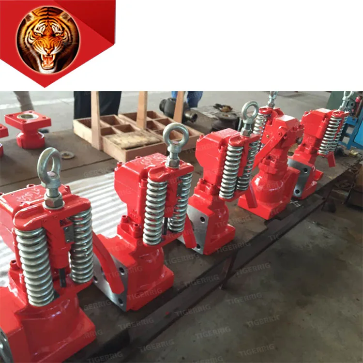
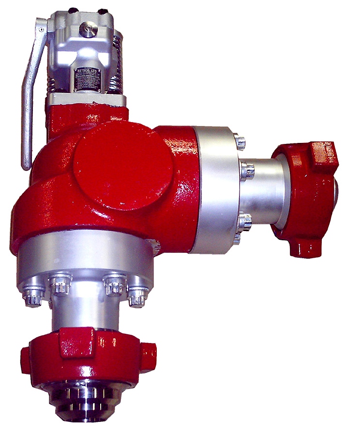
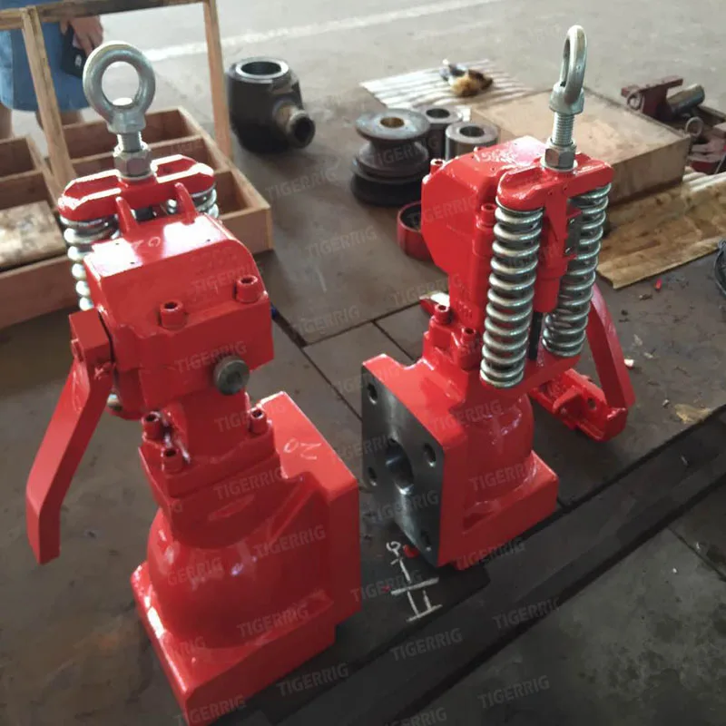
Outside the pump, but still an important part of the system, is the pop-off, or pressure relief valve. When you plug the bit, or your brother-in-law closes the discharge valve on a running pump, something has to give. Without a good, tested pop-off, the part that fails will be hard to fix, expensive and probably hurt somebody. Pop-off valve are easily overlooked. If you pump cement through your rig pump, it should be a standard part of the cleanup procedure. Remove the shear pin and wash through the valve. In the old days, these valves were made to use a common nail as the shear pin, but now nails come in so many grades that they are no longer a reliable tool. Rated shear pins are available for this. In no case should you ever run an Allen wrench! They are hardened steel and will hurt somebody or destroy your pump.
One last thing that helps pump maintenance is a good pulsation dampener. It should be close to the pump discharge, properly sized and drained after every job. Bet you never thought of that one. If your pump discharge goes straight to the standpipe, when you finish the job your standpipe is still full of fluid. Eventually the pulsation dampener will water-log and become useless. This is hard on the gear end of the pump. Open a valve that drains it at the end of every job. It’ll make your pump run smoother and longer.

Safety is of the utmost importance when dealing with pressure relief valves. The valve is designed to limit system pressure, and it is critical that they remain in working order to prevent an explosion. Explosions have caused far too much damage in companies over the years, and though pressurized tanks and vessels are equipped with pressure relief vales to enhance safety, they can fail and result in disaster.
That’s also why knowing the correct way to test the valves is important. Ongoing maintenance and periodic testing of pressurized tanks and vessels and their pressure relief valves keeps them in working order and keep employees and their work environments safe. Pressure relief valves must be in good condition in order to automatically lower tank and vessel pressure; working valves open slowly when the pressure gets high enough to exceed the pressure threshold and then closes slowly until the unit reaches the low, safe threshold. To ensure the pressure relief valve is in good working condition, employees must follow best practices for testing them including:
If you consider testing pressure relief valves a maintenance task, you’ll be more likely to carry out regular testing and ensure the safety of your organization and the longevity of your
It’s important to note, however, that the American Society of Mechanical Engineers (ASME) and National Board Inspection Code (NBIC), as well as state and local jurisdictions, may set requirements for testing frequency. Companies are responsible for checking with these organizations to become familiar with the testing requirements. Consider the following NBIC recommendations on the frequency for testing relief valves:
When testing relief valves, keep in mind that they have two basic functions. First, they will pop off when the pressure exceeds its safety threshold. The valve will pop off and open to exhaust the excess pressure until the tank’s pressure decreases to reach the set minimum pressure. After this blowdown process occurs, the valve should reset and automatically close. One important testing safety measure is to use a pressure indicator with a full-scale range higher than the pop-off pressure.
Thus, you need to be aware of the pop-off pressure point of whatever tank or vessel you test. You always should remain within the pressure limits of the test stand and ensure the test stand is assembled properly and proof pressure tested. Then, take steps to ensure the escaping pressure from the valve is directed away from the operator and that everyone involved in the test uses safety shields and wears safety eye protection.
After discharge – Because pressure relief valves are designed to open automatically to relieve pressure in your system and then close, they may be able to open and close multiple times during normal operation and testing. However, when a valve opens, debris may get into the valve seat and prevent the valve from closing properly. After discharge, check the valve for leakage. If the leakage exceeds the original settings, you need to repair the valve.
According to local jurisdictional requirements – Regulations are in place for various locations and industries that stipulate how long valves may operate before needing to be repair or replaced. State inspectors may require valves to be disassembled, inspected, repaired, and tested every five years, for instance. If you have smaller valves and applications, you can test the valve by lifting the test lever. However, you should do this approximately once a year. It’s important to note that ASME UG136A Section 3 requires valves to have a minimum of 75% operating pressure versus the set pressure of the valve for hand lifting to be performed for these types of tests.
Depending on their service and application– The service and application of a valve affect its lifespan. Valves used for clean service like steam typically last at least 20 years if they are not operated too close to the set point and are part of a preventive maintenance program. Conversely, valves used for services such as acid service, those that are operated too close to the set point, and those exposed to dirt or debris need to be replaced more often.
Pressure relief valves serve a critical role in protecting organizations and employees from explosions. Knowing how and when to test and repair or replace them is essential.
Your pressure relief valves (PRVs) are some of the most important pieces of equipment in your plant. They are what protects your systems from overpressure events that can damage your systems and, in some cases, have catastrophic consequences.
Safety valves and pressure relief valves are essential to ensure safe operating pressures. Proper installation of these valves significantly reduces the chance of danger to people and damage to system components. This article looks closely at the installation procedures of safety and pressure relief valves.
Safety valves and pressure relief valves have similar installation procedures but different operations. As soon as the system’s pressure reaches a safety valve’s set pressure, the valve opens rapidly to reduce pressure in the system quickly. The safety valve does not begin closing again until the system pressure is very close to the safety valve’s reseating pressure. A pressure relief valve also begins opening when the system’s pressure reaches the valve’s set pressure. However, a pressure relief valve opens proportionally to the increase in pressure. Similarly, it closes proportionally to the system’s pressure dropping. A pressure relief valve works to relieve pressure without rapidly decreasing system pressure. Read our article on the differences between safety and pressure relief valves to learn more.
This section covers guidelines for before, during, and after the installation of safety valves or pressure relief valves. The guidelines apply to both types of valves.
Vertical position:Install valves in a vertical position with the stem facing upwards unless the valve design explicitly allows a different orientation.
Maintenance schedule:Ensure a schedule is in place for regularly testing the valve. Pressure relief and safety valves require testing at least once a year. Valves that operate more frequently may require more frequent testing.


 8613371530291