
mud pump pressure problems made in china

The feasibility of applying delay pressure detection method to eliminate mud pump pressure interference on the downhole mud pressure signals is studied. Two pressure sensors mounted on the mud pipe in some distance apart are provided to detect the downhole mud continuous pressure wave signals on the surface according to the delayed time produced by mud pressure wave transmitting between the two sensors. A mathematical model of delay pressure detection is built by analysis of transmission path between mud pump pressure interference and downhole mud pressure signals. Considering pressure signal transmission characteristics of the mud pipe, a mathematical model of ideal low-pass filter for limited frequency band signal is introduced to study the pole frequency impact on the signal reconstruction and the constraints of pressure sensor distance are obtained by pole frequencies analysis. Theoretical calculation and numerical simulation show that the method can effectively eliminate mud pump pressure interference and the downhole mud continuous pressure wave signals can be reconstructed successfully with a significant improvement in signal-to-noise ratio (SNR) in the condition of satisfying the constraints of pressure sensor distance.
In measurement while drilling (MWD), various downhole signals will be transmitted to the surface in real time for instructing the drilling operation. One of the most common methods of transmitting the measured downhole information to the surface is through mud pressure pulses produced by mechanical modulation of a mud siren in MWD tools and transmitted at acoustic speed in the mud flow. The mud siren generates mud continuous pressure wave signals with complex modulation methods to produce higher data rates. When transmitting the mud pressure signals, there will be a lot of pressure noise and interference, among which the mud pressure fluctuation generated by the mud pump contributes to the largest influence. The mud pump pressure interference is related to the pump stoke rate which includes fundamental component and harmonic component. When the mud pump is in imbalance operation mode caused by sealing problem or in abnormal working status, some higher harmonic amplitude will become very large. Although the pressure dampers are equipped on mud pump pipe, the pressure fluctuation generated by mud pump reaches or exceeds the downhole signal strength detected in the stand pipe [1]. These higher harmonics will enter the frequency band of mud pressure signal and thereby create great interference that cannot be eliminated by conventional signal processing method, leading to the great decrease of signal-to-noise ratio (SNR) of signal and affecting extraction of the MWD signals. Many studies had been done to eliminate the pump interference. Marsh and others proposed the matched filter method which treated mud pump interference as random noise and calculated the autocorrelation coefficient to eliminate the mud pump pressure interference [2]. However, the pump interference is a kind of system interference rather than random noise, so the conclusions of the method needed further discussion. Brandon and others proposed an adaptive compensation method which uses extracted interference component in the signal and automatically adjusts strength of the interference component to eliminate the pump pressure interference impact on the signal [3], but the effect was limited. Some literatures [4–7] introduced the delay pressure detection technique and built a mathematical model, being fitted to the single-frequency signal with pressure sensors distance of quarter signal wavelength, for eliminating the mud pump pressure interference. Because components of many frequencies are contained in mud continuous pressure wave signals, the mathematical model presented in those literatures cannot be applied in reconstruction of actual mud continuous pressure wave signals. Based on transmission path analysis of mud pump pressure interference and downhole mud pressure signals, the authors established the mathematical model in time domain for processing mud continuous pressure wave signals according to the fundamental mathematical principle of delay pressure detection method and then studied the reconstruction method of mud continuous wave signals in both time domain and frequency domain and constraints of the distance between pressure sensors.
The delay pressure detection method uses two pressure sensors being some distance apart on the mud pipe to detect and process the mud pressure signal; Figure 1 shows the schematic figure of mud pressure signal detection system. Two pressure sensors, A and B, having distance between each other, are equipped in a straight pipe between wellhead and mud pump. The pressure signals received by two sensors contain downhole signal (mud pressure signal) , downhole random noise , and mud pump pressure interference . The transmission direction of pump pressure interference is opposite to that of downhole signal. Suppose that the propagation velocity of the mud pressure wave is and the pressure wave transmission time between sensors A and B is .
Suppose that is unit impulse response of the linear system . When the signal is being transmitted through the linear system [8], signals received by the pressure sensors A and B can be expressed as
According to (5), the time-domain solution of the system frequency response can be described as the reconstruction of the downhole signal after the delay pressure detecting signal is passed through a signal recovering system with frequency transfer function .
Considering that the maximum frequency of mud continuous pressure wave signal in transmission will be dozens of hertz (Hz), the signal frequency is lower and limited. In limited frequency band, the signal attenuation in amplitude will keep unchangeable when mud continuous pressure wave signal passes the straight pipe between pressure sensors A and B, so the pipe can be seen as an undistorted transmission system and regarded as an ideal low-pass filter. The frequency domain transfer function of the system can be described as
Equations (13) and (11) have the same structure, so the essence of signal reconstruction process in time domain is to make the delay pressure detecting signal pass through a closed-loop delay feedback system with recursive structure.
The straight pipe between pressure sensors A and B will cause pressure signal attenuation. According to the transmission characteristics of mud pressure wave [11], the attenuation coefficient of pressure signal or the amplitude ratio of mud pipe can be described as
where is the pipe length between pressure sensors A and B, is the attenuation index, is the volume fraction of gas in mud, is the volume fraction of solids in mud, is the bulk modulus of gas in mud, is the bulk modulus of liquid in mud, is the bulk modulus of solid in mud, is the bulk modulus of the mud pipe, is the internal diameter of the mud pipe, is the wall thickness of the mud pipe, is the Poisson’s ratio of the mud pipe, is the kinematic viscosity of mud, and is signal frequency.
Suppose that the mud is water-based mud. The computational conditions are listed as follows [12]: internal diameter of the mud pipe is 108.6 mm, wall thickness of the mud pipe is 9.2 mm, the mud kinematic viscosity is 20 mPa·, the pipe Poisson’s ratio is 0.3, volume fraction of gas in mud is 0.5%, volume fraction of solid in mud is 15%, the mud pipe bulk modulus is 210 GPa, and bulk modulus of water in mud is 2.04 GPa, bulk modulus of solid in mud is 16.2 GPa. If signal frequency of mud continuous pressure wave is , when the distance between pressure sensors A and B is less than , the pressure signal attenuation coefficient will be by numerical calculation. This means that transmission loss of mud pressure wave signal is very small and the attenuation coefficient will be close to 1 when the two sensors are nearer to each other.
If the maximum frequency of mud pressure signal spectrum is , there is . When the corresponding pole frequency falls into the passband of ideal low-pass filter, the pole frequency will be very likely to enter signal spectrum and generate great interference in the reconstruction of downhole signal. To avoid such situation, all the pole frequency values should be greater than the passband frequency of ideal low-pass filter. That is, .
Propagation velocity of the mud pressure wave in the mud pipe can be calculated according to the literature [13]. Take the mud pressure DPSK (differential phase shift keying) signal with carrier wave frequency of 24 Hz for example, the maximum frequency of signal spectrum is 36 Hz. When Hz, we have s. Furthermore, if the mud pressure wave velocity is m/s, the corresponding distance between pressure sensors is m.
The numerical simulation takes mud pressure DPSK signal as an example. According to the mathematical model of mud pressure DPSK signal [14], the signal can be formulated as . In the formula, carrier frequency is Hz, signal amplitude is Pa, and data code is . By analyzing the power spectral of mud pressure DPSK signal, the maximum frequency of signal spectrum is Hz and the signal power is . Mud pump interference simulates multifrequency pressure pulsation generated by triplex pump with pump impulse rate 64 r/min, and the fundamental wave frequency is with harmonic orders 2 to 9. Therefore, the frequency changing range of pump interference is from to . Suppose that the fundamental wave and every harmonic wave amplitude are . The corresponding power density of fundamental wave or every harmonic wave is an impact function and the average power of the pump interference is
Figure 2 shows the signal waveform and the signal spectrum mixed with mud pump interference. It can be seen that the mud pressure DPSK signal is completely submerged in the pump interference in time domain and the signal spectrum is completely covered by mud pump interference frequencies.
Suppose that the signal acts on the at , has zero state response only, and the system output before is . Simulation result of the reconstructed signal by MATLAB programming is shown in Figure 3. It can be seen that the mud pump interference is eliminated after delay pressure detection from Figure 3(a); the reconstructed signal in Figures 3(b) and 3(c) are consistent with the mud pressure DPSK signal in Figure 2(a). In Figure 3(b), the numerical calculation result shows that the SNR of reconstructed mud pressure DPSK signal under condition of ms is 72.4, which is about 657 times higher than that of existing pump interference. Numerical calculation and analysis show that the SNR of reconstructed mud pressure DPSK signal will be affected by the delayed time in time domain and the influence is listed in Table 1. The reason is that the set value of , participating in the recursive computation in (11), will be increased with the delayed time , but the influence is not notable. In Figure 3(c), the reconstructed mud pressure DPSK signal based on inverse Fourier transform method has no distortion in whole waveform and is better than the signal reconstructed by time-domain differential equation method in quality. However, both reconstruction methods can reconstruct downhole signal effectively.
(1) Theoretical analysis and numerical simulation show that delay pressure detection method can effectively eliminate mud pump interference and realize reconstruction or recovery of mud continuous pressure wave signals with greater SNR.
(2) To avoid the pole frequency entering into the signals frequency band in signal reconstruction, the distance between pressure sensors should be determined according to the highest signal frequency and the minimum wave velocity.
(3) According to the mathematical principle analysis of delay pressure detection method, it is only applied to eliminate special interference (mud pump pressure interference) whose transmitting direction is opposite to that of the downhole signal. For mud continuous pressure wave signal which is seriously affected by mud pump interference, this method has some inspiration effect on solving the problem of mud pump pressure interference.

Drilling consumables such as mud pump systems and their components can drastically increase your uptime while reducing costs and health/safety/environmental (HSE) risks. To support your drilling needs, Forum’s patented P-Quip® mud pump system offers a single-source solution that integrates high-quality fluid end components for maximum longevity and performance.
With more than 20 years of successful operation in severe environments, P-Quip offers a proven track record for the lowest cost of ownership in the industry. As part of our commitment to quality, our mud pump parts use patented Banded Bore™ technology that significantly reduces stress concentrations and leads to longer module life.
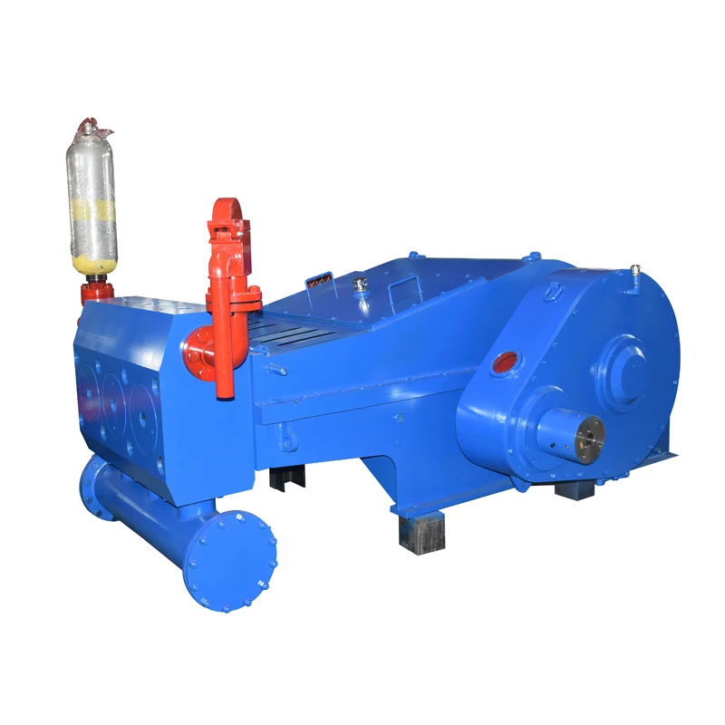
Piston high-density pump is one of capital equipment of core drilling engineering, and its effect is to provide the cooling drill bit of highly pressurised liquid (water), in the Hydraulic and Hydro-Power Engineering prospecting, is also the capital equipment of water pressure test in borehole usually.Piston high-density pump mainly is comprised of transmission system (gear), connecting rod, pump head (inlet valve, drain valve), frame.The piston of piston high-density pump is realized the linear reciprocating motion in pump chamber by transmission system (gear) and connecting rod, thereby changes volume realization water suction and the draining of pump chamber.The fluid pressure of piston high-density pump output has pulse characteristic.The pulse of fluid pressure affects the working life of pipeline, the correct collection of impact to test data in water conservancy and hydropower drilling project water pressure test in borehole.As shown in Figure 1, in order to reduce the pulse of pressure, prior art is to install an air chamber as stable-pressure device 3 on the outlet pipe 4 of piston high-density pump 2, the pressurized vessel that described stable-pressure device 3 is a cavity, be provided with through hole 5 in the bottom of pressurized vessel, the through hole 5 of pressurized vessel is connected on outlet pipe 4 by three-way pipe.1 is intake pipe.
Its principle of stabilized voltage is that the compression property of application gas is subdued crest and the trough with compensatory pressure pulsation liquid, realizes the stable of pressure.When the water pressure of discharging when pump is large (crest), the high pressure water in outlet pipe 4 makes the air compressing of air chamber, and air pressure increases, and water pressure reduces; When the water pressure hour (trough) that pump is discharged, the air spreading of air chamber, air pressure reduces, and water pressure increases.Thereby reduce the water pressure fluctuation in outlet pipe 4.
But, the stable-pressure device of prior art (pressurized vessel), the air in pressurized vessel with the liquid in outlet pipe without separating, pump is in operation, liquid in outlet pipe is often invaded in pressurized vessel, in outlet pipe 4, causes voltage regulation result poor part Bas Discharged in the air chamber pressurized vessel.

Mud Pump Pressure is extremely important to the drilling process. The Mud Pump Pressure Gauge enables the driller to monitor the pressure while drilling. Any unusual change in pressure will alert the driller of down hole problems. Pressure too low could indicate washed out pipe or bit nozzle, loose joint or broken drill string, worn pump packing or liners, or lost returns due to formation breakdown. Pressure too high could indicate a plugged drill bit or an increase in mud density or viscosity. Reliable indication of mud pump pressure provides an early warning of circulation problems, enabling the driller to make corrections avoiding major problems.

Mud pump is the key equipment in drilling operation. If mud is compared to blood in drilling operation, mud pump is the heart of blood supply in drilling production. Therefore, its importance in drilling production is self-evident, and the spare parts of mud pump play a certain role in this.
Mud pump is a kind of machine which can transport mud or water to drill hole in the process of drilling. It is an important part of drilling equipment. Its main function is to inject mud into the well with the bit, cool the bit, clean the drilling tool, stabilize the well wall, drive the drilling, and bring the cuttings back to the ground after drilling.
In the normal circulation drilling, the mud pump is to send the surface flushing medium - clear water, mud or polymer flushing liquid under a certain pressure through the high-pressure hose, faucet and the center hole of drill string directly to the bottom of the drill bit, so as to cool the drill bit, remove the cuttings and transport them to the surface. The mud pump is driven by the power machine to rotate the crankshaft of the pump. The crankshaft drives the piston to do reciprocating motion in the pump cylinder through the crosshead. Under the alternating action of the suction and discharge valves, the purpose of pressing and circulating the flushing fluid is realized. Different types of mud pumps are used in different cases to ensure the smooth proceeding of the drilling operation.
According to the use of the mud pump, the leakage of the valve box, the burning of the bearing and the abnormal noise are all frequent faults that affect the normal use of the mud pump. Therefore, careful study of the causes of the problem plays a key role in prolonging the service life of the mud pump. At this time, a certain amount of spare parts of the mud pump are needed.
In the process of using the mud pump, the equipment failures caused by specific reasons are different. Reasonable use and maintenance of the equipment can extend the service life of the equipment. At the same time, in strict accordance with the basic elements of normal operation of the drilling pump, "medium power, medium pump pressure, medium speed operation, tight, tight, leak tight, pump pressure does not fluctuate, temperature is normal, sound is normal", the operation can ensure the good operation of the equipment. Of course, it"s also important to find the right mud pump spare parts!

Mud centrifugal pumps are mainly design for solids control circulating system of oilfield drill rig. It can be used to provide drilling liquid with a certain discharge capacity and pressure to sand, desilter and mud mixer, to assure these equipments work efficiently.

General Pump balances technology, engineering, and stellar customer service. A world class distribution center, we bring you the exact pump products you need, backed up by industry knowledge and decades of expertise. We supply pump products for a wide variety of markets and applications, and are unfailingly committed to our customers’ satisfaction and success.

Valve assembly is the critical component of mud pump fluid end , with high operation frequency and great impact subjected. The quality of valve assembly will have a direct effect on the life of hydraulic cylinder.
Piston assembly is the major part of the mud pump fluid end. The discharge pressure of mud pump is generated by the up-and-down motion of the piston in the cylinder. Small piston—high pressure and low flow rate; Big piston—low pressure and high flow rate. Metric pump and inch pump adopts metric piston and inch piston respectively.


 8613371530291