
mud pump pressure problems quotation

The fluid end of a duplex or triplex pump offers hundreds of opportunities for error. The results of an error in such a high-pressure system can mean (1) expensive downtime on the pump and maybe the entire rig, (2) expensive repair-replacement, and (3) possible injury or death of a crewman or a company man. Under the laws of nature, pump pistons and liners will wear, and there will be some corrosion and metallurgical imperfections, but the majority of pump failures are manmade. Theoretically, thorough training and retraining should avoid most mud pump problems. Realistically, a critical failure analysis during repair will be necessary to determine how to correct the failure. Telltale signs of trouble are distortion of piston rods, frayed piston polymer, discoloration, odor, hard-to-remove piston, rod cracks, pitting, total fracture, valve seat wear, and unsuitable external appearance.

abstractNote = {Failure of a liner seal is one of the more critical failures on a mud pump because this seal interfaces with the pump body. Therefore, failures, usually damage the pump body, leading to repair or replacement of the fluid end itself. One of the more common liner seal problems involves counter-bore-type seals. This type of seal is easily affected by two aspects of the problem that are found in the mud pump fluid end-wear and foreign matter in the seal groove. Factors relative to difficult liner removal are discussed. Piston damage, careless seal installation and corrosion damage are also examined.},
The article presents selected technical issues relating to drilling performed by a drillship, one type of drilling rigs. Basic problems encountered in the main function of such rigs − drilling a well − are failures of mud pumps. The authors investigate these pumps in operational conditions, aiming at development of a system for monitoring the technical condition of these pumps. Work on a diagnostic system is in progress that will permit to predict the condition of mud pump valves well in…Expand
Mud pump liner selection in today"s drilling operations seldom (at best) considers electrical implications. Perhaps, with more available useful information about the relationships between mud pump liner size and operational effects on the electrical system, certain potential problems can be avoided. The intent of this paper is to develop those relationships and show how they affect an electrical system on example SCR rigs.Introduction
There, seems to be little consideration for the relationships between liner size and demand on a rig"s engine/generator set(s). Yet, consideration for this relationship can prove to be very helpful to drillers and operators in efficiency of a rig"s electrical system. In order to develop the relationships and help drillers and operators understand the importance of each, relationships between liner size, pump speed, pump pressure, and electrical power will be developed. Only basic physical laws will be used to develop the relationships; and, once developed, the relationships are readily applied to realistic examples utilizing a mud pump manufacturer"s pump data. Finally, conclusions will be drawn from the examples.DEVELOPMENT OF RELATIONSHIPS BASIC RELATIONSHIPS
where HHP= Hydraulic horsepower, GPM = Mud pump volumetric flow rate in gallons per minute, and PST Mud pump output pressure in pounds peer square inch.
Hydraulic horsepower is reflected to the mud pump motor via a multiplier for mechanical efficiency. it follows that motor horsepower is then represented by

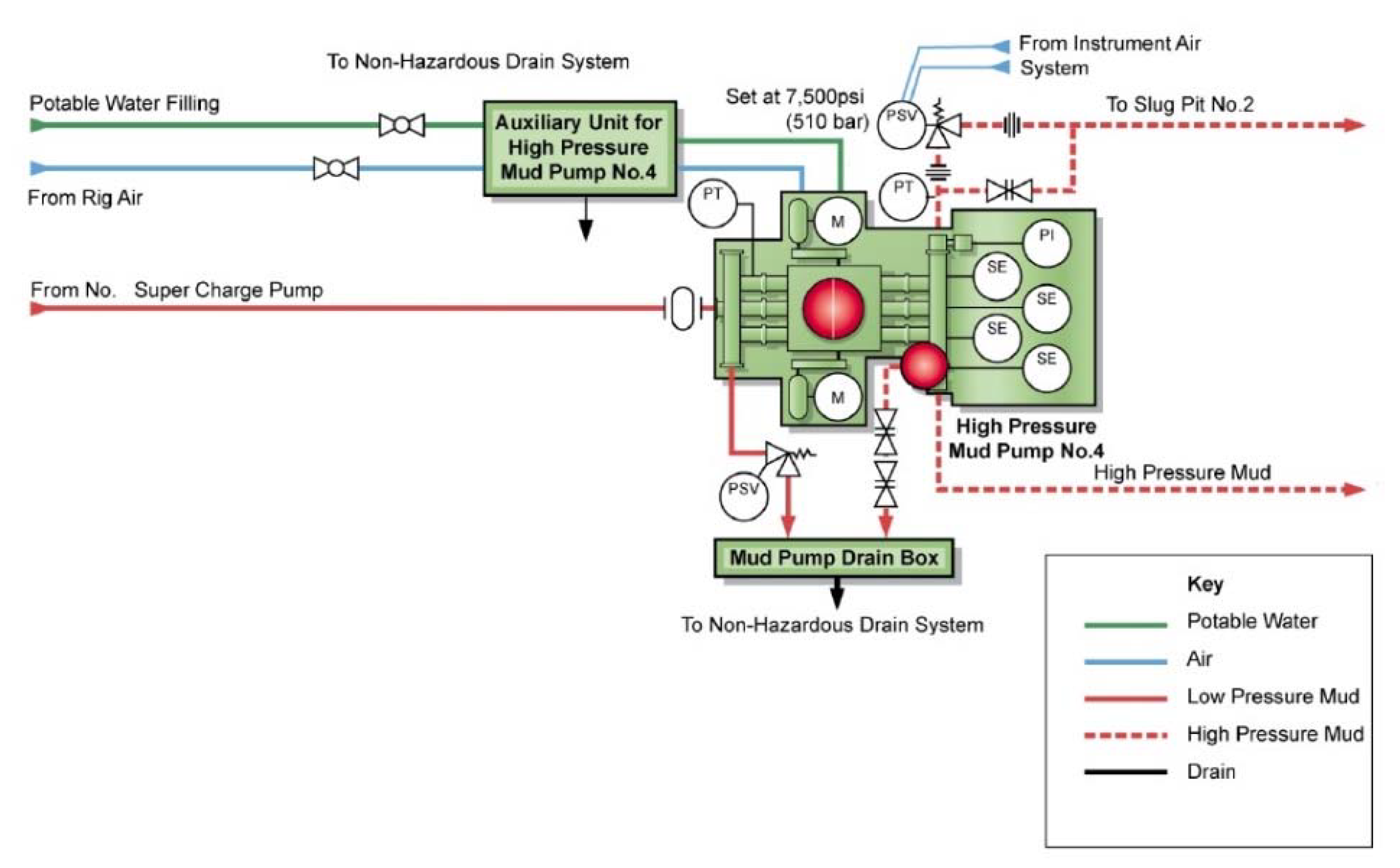
Whether onshore or offshore, well drilling sites rely on a multitude of systems to successfully perform the drilling operation. The mud pump is a key component tasked with circulating drilling fluid under high pressure downhole. The mud pump can be divided into two key sections: the power end or crosshead and the fluid end. Proper alignment of the pump’s crosshead to the fluid end liner is necessary to maximizing piston and liner life. Misalignment contributes to
accelerated wear on both the piston and the liner, and replacing these components requires downtime of the pump. Traditional methods of inspecting alignment range from using uncalibrated wooden rods, Faro Arms and micrometers to check the vertical and horizontal alignment of the piston rod OD to the piston liner ID. These are time consuming and cumbersome techniques that are ultimately not well suited to troubleshoot and solve alignment issues.
A “Mud Pump Laser Alignment Kit” enables you to measure where the piston will run through the liner at various positions along the pump’s stroke. It will also project a laser centerline from the fluid end back towards the rear power end of the pump that can be used to determine how much shimming is required to correct any alignment issues. The kit can include either a 2-Axis receiver or a 4-Axis which accepts the laser beam and documents where it falls on the active surface of the receiver. The 4-Axis receiver can decrease alignment time by as much as 50% as it will measure angularity as well as X and Y while the 2-Axis does not and will need multiple measurement locations to get the same information. In addition, the alignment system is a non-intrusive service requiring the removal of only the piston rod which allows for much quicker service and less down time on the pump. As the mud pumps in question are located globally both on and offshore, having a small, portable system is another great advantage. Our recommendation would be Pinpoint laser System’s “Mud Pump Alignment Kit”. They are being used by many of the leading repair service companies and have been their main alignment tool for over 15 years. Manufacturers are also utilizing these for new pump set-up.

Insufficient NPSH AvailableSuction pressure is incorrect meaning pump is cavitating. Ensure all valves are open, check liquid temperature. To correct increase fluid in tank, check for air ingress, remove unnecessary bends, increase pipe diameter, install feed pump.
Ensure all valves are open, check liquid temperature. To correct increase fluid in tank, check for air ingress, remove unnecessary bends, increase pipe diameter, reduce fluid temperature, install feed pump.
PulsationSuction pressure is incorrect meaning pump is cavitating. Ensure all valves are open, check liquid temperature. To correct increase fluid in tank, check for air ingress, remove unnecessary bends, increase pipe diameter, reduce fluid temperature, install feed pump.
Seals or CupsScored PlungersCheck for Chemical wear, hard water, and abrasive particles. Increase service intervals as high wear to lo and high pressure seals can cause male adapter to come into contact with plunger.
Inlet pressure too HighMaximum inlet pressure for piston pumps is 40psi (2.75 bar) and plunger pumps is 60-70psi (4-4.8bar). K Style pumps can accept higher inlet pressures.
Pump Dry RunningCheck Fluid level and that NPSHR is being met. Check inlet pipework, and filters for blockage, long suction lines, and presence of air ingress
Water in CrankcaseSpraying / Air CondensationProtect pump from direct spray with ventilated enclosure if necessary. Contaminated oil will damage bearings and other components within the drive.
Worn AdaptorSplit manifold designs of pumps have adapters within the pumps. Check O rings when servicing seals and valves and replace as required.
Manifold Wear / DamageCheck chemical compatibility of fluid and any cleaning fluids used. Operation with worn seals and o rings can accelerate manifold wear. Erosion can be limited by freshwater flushing between pump use.
Manifolds can be damaged by over pressure which may be caused by high inlet pressure, relief valve or regulating valve failure or blockage within pump.
Crown Oilfield Instrumentation’s mud pressure gauges are extremely accurate and widely used in the harshest drilling environments. Each of our mud pressure systems are designed to meet or exceed API specifications, and you can count on a Crown mud pump pressure gauges to stand up to whatever the oil and gas industry can throw at them. Our mud pressure systems monitor the pump pressure for a variety of pumps and applications to ensure that you are getting the most out of your drilling fluids. Our single pointer systems use a 6" aluminum cast gauge to detect the slightest pressure changes and come with three different sensors: diaphragm gauge protector, 1:1 piston separator and 4:1 debooster gauge protector. The Crown compound pointer system uses unique pointer design that affords the reader to see the smallest pressure changes at a glance. Crown"s unitized pressure gauges are gauge and protector in one and can be mounted on a standpipe and seen up to 60 ft. away. Crown’s pressure gauges are designed, developed and tested to be durable, reliable and dependable, and all systems can stand up to the rigors of the oilfield. Manufactured in the US, you can depend on our pressure gauge systems to provide years of service.

Over the last decade, we have seen a huge increase in the sale of constant pressure pumps. Everyone sells them and most people are buying them. Everyone wants better pressure and many of you are willing to pay more to get it. Here are my thoughts.
When the pump turns on. A conventional water system turns on the pump when the pressure drops 20 psi. A pressure switch controls the pump and usually turns the pump on at 40 psi and off at 60 psi. A constant pressure water system is controlled by a pressure sensor. The controller usually turns the pump on when the pressure drops by only 5 psi. This means that you won’t have a large fluctuation in the pressure and that is why it is called a “constant pressure system”.
The speed that the pump runs. On a conventional system, the pump runs at full speed or not at all. It is either turning 3,450 rpm or zero. A constant pressure system will vary the speed of the pump to maintain a constant pressure. You might be taking a shower and only using 4 gpm. The pump will run the entire time you are using water. But, instead of running at full speed and turning off, it will turn slowly and maintain the pressure the whole time. Its kind of like “cruise control” for your well pump.
There are built in pump protections. Most controllers do a good job of protecting the pump from dry run, voltage supply issues, waterlogged pressure tanks, etc.
Some controllers can email or text you if there is a problem. Usually these devices are additional to the constant pressure controller, but this is an option on many units.
The controllers can have problems with rural power supplies. The unit is basically a computer and it can be damaged by voltage spikes that are more common in rural areas. You should consider the power supply to your property before purchasing one of these units. If you do get one, make sure you get some sort of surge protection.
The controllers don’t like hot weather. They produce a lot of heat and they have to stay cool. So, when it is really hot outside, you might find that your controller will stop working or at least slow the pump down due to the excessive heat. Conventional systems rarely have this issue.
You don’t get the best pump protection. While the units do have built in pump protection, they are not the best at protecting your pump. A simple Pumpsaver is a great unit on a conventional system, but it won’t work on a constant pressure system. If you want great protection, stick with the original.
Do they work? Yes and no. Yes, they do a great job of keeping the pressure right in the range that you like. But, they don’t pump more water than conventional pumps. In fact, they use the exact same pump but with a different motor. So, if you have a problem with low water pressure due to high demand (like when the irrigation system is running) then switching to a constant pressure system will do nothing for you.
Is it worth it? Only you can decide that. Are you willing to pay more money and have more potential nuisance issues so that you can have very little fluctuation in pressure? A growing number of you are saying yes.

GDEP is the original creator of the drilling pump and continues to set the standard for durable, high-quality drilling pumps that can withstand the world’s toughest drilling environments. Starting with our PZ7 and rounding out with the market"s most popular pump, the PZ1600, our PZ Series of pumps are the perfect choice for today"s high-pressure drilling applications.

Your process pressure instruments play a critical role in your applications. They accurately and reliably measure and monitor pressure to determine if process systems are working effectively and efficiently, or if you need to make system alterations or adjustments. This helps ensure the safety of your personnel, the efficiency of your processes and the quality of your products.
In my 41 years of working in the process industry, I’ve seen many causes of instrument failure. These “instrument killers” can throw a wrench in your project and cause all types of problems. Luckily, most of them can be prevented if you know the warning signs.
In this article, I will outline the most common instrument killers that endanger your pressure equipment. Although the focus of this blog is on pressure gauges, when the word instrumentis used, the reference is to a gauge, a pressure switch, or a transducer.
Instrument maintenance is one of the keys to achieving and maintaining personnel safety, process efficiency and product quality. A comprehensive maintenance plan makes it easier for you to identify instrument issues and execute appropriate solutions before they become more significant or widespread problems. This helps save you time and money by preventing costly service work, unplanned downtime and equipment or process-based employee injuries.
Component DamageVarious components of the gauge may have damage. For example, the pointer may be dented, a sign the gauge has been severely under or overpressure. In a liquid-filled gauge case, yellowed fill usually indicates elevated ambient temperature at the gauge. Also, the dial may be discolored, which is another sign of elevated temperature.
A melted or deformed gauge window, usually acrylic, is also a sign of extreme elevated temperature. The gauge window and dial are coated in a black powder making gauge readability an issue. This is typically the result of excessive pulsation and/or vibration that causes fretting or wear of the gauge movement teeth. Among others, these signs serve as indicators of underlying gauge issues. If you can recognize them and understand their causes, you will be better prepared to diagnose and resolve problems that may occur in your own process instruments.
Like many of my colleagues in the industry, you may also encounter problems when using instruments in your critical applications. The key to overcoming them is recognizing their signs and understanding their causes. This information makes it much easier to determine and execute the right solution.
Below are some of the most common pressure instrument problems, including why they occur, what effects they have on the instrument and the overall operation or process, and how to resolve them.
In processing equipment, surges in process pressure can lead to pulsation in gauges. These pulsations can cause poor gauge readability due to pointer flutter and decreased gauge integrity due to component damage.
The Ashcroft MicroTube™orfinned siphonare rigid devices mounted directly to the instrument and then to the process so there is no need to consider how to mount the instrument if it were remotely mounted. The MicroTube™ siphon has been engineered for process pressures to 5000 psi and process temperatures to800°F (427°C). Thefinned siphon is rated for pressures to 3000 psi and process temperatures to700°F (371°C). Both devices are good temperature dissipaters.
Pressure spikes have many causes, including water hammer, overly rapid valve actuation, equipment malfunction or process fluid freezing. Gauges subjected to these conditions often show signs of damage like a dented pointer, a ruptured or deformed tube, or a broken segment gear. This damage can lead to unresponsiveness to changes in process conditions or complete instrument failure, both of which can result in poor operation or performance in your process.
Pressure spikes or surges beyond the full-scale range of a gauge or overpressure can result in accuracy degradation, gauge failure or rupture of the bourdon tube.
Integrating an internal stopYou can integrate an internal stop/overload stop to increase gauge proof pressure. This device typically increases gauge proof pressure by an additional 20%.
Installing a pressure limiting valve (PLV) or a gauge with high overpressure capabilityThis accessory device can be set to shut off at the full-scale range of the gauge. When process pressure falls below the full-scale gauge range pressure, the PLV will reset and allow process pressure to flow through the instrument. Another option to consider is a gauge with high overpressure capability like theAshcroft T6500 with the XRA option. This gauge allows for overpressure up to 400% of the gauge range.
Selecting a new, properly rated gaugeYou should choose a new gauge that accommodates the maximum operating pressure. For optimal readability, the gauge pointer should normally operate at 12:00 on the dial face. If the normal operating pressure of the gauge is 50 psi, choose a full-scale range twice the operating range or 0/100 psi.
If you want to avoid instrument problems stemming from corrosion, you should ensure the material for the instrument’s wetted parts is suitable for the process material’s composition, concentration and temperature. If it is not possible to choose a compatible instrument wetted parts material, you can integrate a diaphragm seal/instrument isolator or isolation ring constructed from an appropriate material for the process. Refer to the
I hope you are now equipped with the knowledge you need to keep your people and processes safe and secure. If you know what problems to look out for and how to solve them, you won’t have to fear “instrument killers.”


 8613371530291