
mud pump pressure sensor free sample
Want to get a great deal on wholesale wholesale mud pressure sensor online? The good news is that you have landed on the right marketplace. Browse through a wide range of pressure sensors including oil pressure senders, pressure transducers, pressure differentials, wireless pressure sensors, digital hydraulic pressure gauges, differential pressure sensors, and many more on Alibaba.com. Our comprehensive collection gives you the freedom to find the ideal product that matches your requirements. In addition to quality products, you"ll also enjoy discounts when buying differential pressure sensors during our numerous promotional campaigns. Finally, consider filtering the items with features such as complimentary shipping and returns, so you get the full value of your time spent shopping online!
Are you looking for customized wholesale mud pressure sensor? Besides the fact that our piezoresistive sensors and digital pressure sensors offer customizability, Alibaba.com offers a wide range of wholesale pressure sensors at your convenience. Pressure sensors are aimed at measuring the temperature and convert the pressure into a Voltage (V) signal. This voltage output is generally buffered to meet the demands of industry standardized outputs. Additionally, they can supply soft millivolt (mV) releases that feature greater overall frequency response and reduced energy usage, and higher susceptibility to electrical noise thus, being ideal for any applications. Browse through our collection of pressure measuring devices, and let yourself be spoiled by our international wholesalers" deals. Start your search with confidence here on Alibaba.com.
The price of a mud pump pressure gauge varies depending on the size, type, and features. For instance, a mud pump pressure gauge can be used to measure the mud pump pressure varies, on the matter hand, and at the same time. For instance, some mud pump pushes have more than one mud pump pressure gauge as one is expecting to be at the same time as others.
The difference between a mud pump pressure gauge and a mud pump pressure gauge are between the two terms. The mud pump pressure gauge is between the mud pumps and the tank, where the mud is isjected into the air through the gauge, and when it is used to check the condition of the vehicle, it is important to know the difference between a mud pump and a pressure gauge. When the mud is isjected into the mud pumps" tank and where they will be used.

Accurately measuring the level of drilling fluid flow through the mud return line is crucial for monitoring the drilling fluid balance in the wellbore. While several different types of sensors have historically been used for measuring the flow rate of drilling fluid through the mud return line, they have proven to be problematic for drillers and require frequent maintenance.
Paddle flowmeters are damaged by rocks and cuttings over time, with the bowl eventually ending up in the shakers. As a result, mud loggers do not have verification on how the paddle is performing because the paddle arm still points in a downwards position and floats with the mud and seawater stream.
Created and tested over time on offshore rigs, the Cameron mud flow sensor combats moisture and condensation by blowing compressed air at a minimum pressure of 2 bar (self-regulated) from its nozzle and functions well without regular maintenance.

MUD PUMP PRESSURE GAUGE DRILLING INSTRUMENTATION MUD PUMP PRESSURE GAUGE LED LIGHT Model YKN-150 Instruction Manual …Quality is Everything... Telephone: 86-579-87537698, Website: http://www.rigchina.com Mobile:86-1381990420 Fax : 86-579-8753 696, Rev.B Email: sales@rigchina.com MSN:rigchina@hotmail.com SKYPE:RIGCHINA Address: No.80-82,Qiude Rd, West Cheng Industrial Eastate, Yongkang,Zhejiang, Chin
MUD PUMP PRESSURE GAUGE DRILLING INSTRUMENTATION 1. Description Plug in the power supply (gray box) on the back of the gauge, the unit should be ON and the LED should be lit. Independently powered system; over 15 days battery life with continued use Long life span on system components due to consistent current draw from battery The Model YKN-150 LED Light Pump Pressure Gauge main application is the measuring of pulsing pressure such as seen in mud pumps and standpipes, it can also be used for measuring steady pressure in other applications. The dampening parts of the Pump Pressure Gauge...
MUD PUMP PRESSURE GAUGE DRILLING INSTRUMENTATION (3) Gauge mounting: 2” NPT male (4) Application; Mud Pumps and Standpipes 3. Dimensions and Functionality (1) These gauges use a tuning fork, fluid cell system as the main components. This system has proven to be the most reliable for these types of operating conditions. (2) Pump Pressure Gauge Dimensions.
MUD PUMP PRESSURE GAUGE DRILLING INSTRUMENTATION Part breakdown available from Precision upon request. 4. Installation and Operation Instructions (1) Apply thread tape to the male threads and install the gauge on the mud pump. CAUTION: DO NOT WRENCH ON THE AREA DIRECTLY BELOW THE GAUGE FACE THAT IS MARKED WITH A “NO WRENCH HERE” STICKER AS THIS WILL SERIOUSLY DAMAGE THE GAUGE. (2) Loosen the top screw on the gauge 1 full turn as this acts as a pressure relief.
MUD PUMP PRESSURE GAUGE DRILLING INSTRUMENTATION WARNING! FAILURE TO DO SO MAY RESULT IN BODILY INJURY IF THE GAUGE FAILS. (3) The gauge should not be operated over the 2/3rd of full scale for extended periods of time. (4) The fluid in the gauge is RIGCHINA All Weather Gauge oil and should not be replaced with any other type of fluid as it may cause damage to the internals of the gauge. Please contact RIGCHINA if the gauge requires additional fluid. (5) Check the Pump Pressure gauge daily to ensure it is reading properly. The Pump Pressure Gauge should be replaced immediately if it is found...
MUD PUMP PRESSURE GAUGE DRILLING INSTRUMENTATION 6.1 Warranty Rigchina Group Company warrants its products to be free from defects in material and workmanship for a period of 12 months from the time of shipment. If repair or adjustment is necessary, and has not been the result of abuse or misuse within the twelve-month period, please return, freight prepaid, and correction of the defect will be made without charge. Out of warranty products will be repaired for a nominal charge. Please refer to the accompanying warranty statement enclosed with the product. 6.2 Returns For your protection,...

The most common scheme for transmitting measurement information utilizes the drilling fluid within the borehole as a transmission medium for acoustic waves modulated to represent the measurement information. Typically, drilling fluid or "mud" is circulated downward through the drill string and drill bit and upward through the annulus defined by the portion of the borehole surrounding the drill string. The drilling fluid not only removes drill cuttings and maintains a desired hydrostatic pressure in the borehole, but cools the drill bit. In a species of the technique referred to above, a downhole acoustic transmitter known as a rotary valve or "mud siren", repeatedly interrupts the flow of the drilling fluid, and this causes a varying pressure wave to be generated in the drilling fluid at a frequency that is proportional to the rate of interruption. Logging data is transmitted by modulating the acoustic carrier as a function of the downhole measured data.
One difficulty in transmitting measurement information via the drilling mud is that the signal received is typically of low amplitude relative to the noise generated by the mud pumps which circulate the mud, as the downhole signal is generated remote from the uphole sensors while the mud pumps are close to the uphole sensors. In particular, where the downhole tool generates a pressure wave that is phase modulated to encode binary data, such as is disclosed in U.S. Pat. No. 4,847,815 and assigned to the assignee hereof, and where the periodic noise sources are at frequencies which are at or near the frequency of the carrier wave (e.g. 12 Hz), difficulties arise.
Mud pumps are large positive displacement pumps which generate flow by moving a piston back and forth within a cylinder while simultaneously opening and closing intake and exhaust valves. A mud pump typically has three pistons attached to a common drive shaft. These pistons are one hundred and twenty degrees out of phase with one another to minimize pressure variations. Mud pump noise is caused primarily by pressure variations while forcing mud through the exhaust valve.
The fundamental frequency in Hertz of the noise generated by the mud pumps is equal to the strokes per minute of the mud pump divided by sixty. Due to the physical nature and operation of mud pumps, harmonics are also generated, leading to noise peaks of varying amplitude at all integer values of the fundamental frequency. The highest amplitudes generally occur at integer multiples of the number of pistons per pump times the fundamental frequency, e.g., 3F, 6F, 9F, etc. for a pump with three pistons.
Mud pumps are capable of generating very large noise peaks if pump pressure variations are not dampened. Thus, drilling rigs are typically provided with pulsation dampeners at the output of each pump. Despite the pulsation dampeners, however, the mud pump noise amplitude is typically much greater than the amplitude of the signal being received from the downhole acoustic transmitter. To reduce or eliminate the mud pump noise so that the downhole signal can be recovered, different techniques have been proposed, such as may be found in U.S. Pat. Nos. 3,488,629 to Claycomb, 3,555,504 to Fields, 3,716,830 to Garcia, 4,215,425 to Waggener, 4,215,427 to Waggener et al., 4,262,343 to Claycomb, 4,590,593 to Rodney, and 4,642,800 to Umeda. What is common to all of the techniques is that they try to eliminate the mud pump noise by adding the mud pump noise to an inverted version of itself. Most of the techniques utilize two sensors in the mud stream (usually two pressure sensors) and take the difference of signals in an attempt to cancel the mud pump noise without canceling the data signal. Various of the techniques require particular physical arrangements.
The Umeda U.S. Pat. No. 4,642,800 takes a slightly different approach to eliminating mud pump noise. Umeda teaches that an average pump signature may be found by obtaining the pump signatures in the presence of data over a certain number of pump cycles. The updated average pump signature is corrected by interpolation to match the current pump cycle length and is subtracted from the current pump signature to provide the residual data signal. While the technique disclosed in Umeda may be effective for particular arrangements, it has several drawbacks. First, because Umeda averages pump signatures which include data pulses, unless the effect of the data signal over any averaging period is zero (i.e. non-carrier frequency systems), the data signal which is to be recovered will tend to be undesirably subtracted from itself. Second, because Umeda uses only a single strobe per pump cycle, estimates (e.g. interpolations) are utilized which can introduce significant error. Third, Umeda does not disclose in detail how to treat a multi-pump system. In particular, if Umeda assumes that the pump signature for each pump of a multi-pump system is the same as it would be for a single pump system, large errors are introduced in attempting to cancel out the pump noise, as pumps which are working in multi-pump systems will have different signatures than they would it they were working in a single pump system. In addition, because estimates are required for each pump in the multi-pump system, additional error in the multi-pump system is introduced.
It is therefore an object of the invention to provide methods and systems for accurately recovering data signals introduced into drilling mud in the presence of mud pump noise.
It is another object of the invention to provide methods and systems for accurately recovering logging-while-drilling (LWD) or measurement-while-drilling (MWD) information which is modulated in drilling mud by correlating mud pump piston positions to a mud pressure signature in a calibration procedure.
It is a further object of the invention to provide methods and systems for accurately obtaining LWD or MWD information in multiple mud pump systems by allocating noise attributable to each mud pump and by tracking the mud pump piston position of each mud pump.
Another object of the invention is to provide method and systems for recovering LWD or MWD information transmitted through drilling mud by varying the pressure of the drilling mud regardless of the manner in which the information is coded.
In accord with the objects of the invention, methods for recovering a LWD or MWD data signal in the presence of mud pump noise are provided, and generally comprise calibrating the drilling mud pressure as a function of the mud pump piston position, and then tracking the piston position during transmission of the LWD or MWD data signal and using the calibration information to subtract out the mud pump noise. More particularly, calibration is accomplished in the absence of the LWD or MWD data signal to provide a correlation between mud pump piston position and the drilling mud pressure; i.e., the pressure signature as a function of mud pump piston position is obtained. Then, when the LWD or MWD data signal is being provided, the mud pump piston position is tracked such that the pressure due to the pump can be subtracted; i.e., by knowing the mud pump piston position, the pressure due to the mud pump is found and subtracted from the total received signal to provide the LWD or MWD signal. Where a plurality of mud pumps are used, calibration is accomplished by running the mud pumps together in the absence of the LWD or MWD data signal, and processing the received mud pressure signals in the Fourier domain to allocated respective portions of the mud pressure signals to respective mud pumps such that each mud pump is provided with a signature as a function of its own piston position. With the piston position of each mud pump being tracked, the sum of the mud pressure signals generated by the mud pumps based on their piston positions is subtracted from the total received signal to provide the LWD or MWD signal.
According to a preferred aspect of the invention, the calibration procedure is periodically repeated, e.g., each time additional pipe is added to the drill string, thereby eliminating the effects of depth and mud property variation on the system.
FIGS. 8a, 8b, and 8c are respectively the total pump signal, and the signals from pump one and pump two in the multiple pump system calibrated according to FIGS 7a and 7b.
Referring to FIG. 1, the operation of the present invention in a typical drilling arrangement is illustrated schematically. Drilling mud 10 is picked up from mud pit 11 by one or more mud pumps 12 which are typically of the piston reciprocating type. The mud 10 is circulated through mud line 13, down through the drill string 14, through the drill bit 15, and back to the surface of the formation via the annulus 16 between the drill stem and the wall of the well bore 29. Upon reaching the earth"s surface 31, the mud is discharged through line 17 back into the mud pit 11 where cuttings of rock or other well debris are allowed to settle out before the mud is recirculated.
A downhole pressure pulse signaling device 18 is incorporated in the drill string for transmission of data signals derived during the drilling operation by the measurement instrument package 19. Signaling device 18 may be of the valve or variable orifice type which generates pressure pulses in the drilling fluid by varying the speed of flow. A preferred signaling device which generates sinusoidal signals is disclosed in U.S. Pat. No. 4,847,815 assigned to the assignee hereof. Data signals are encoded in a desired form by appropriate electronic means in the downhole tool. Arrows 21, 22, and 23 illustrate the path taken by the pressure pulses provided by the downhole signaling device 18 under typical well conditions. Pump 12 also produces pressure pulses in the mud line 13 and these are indicated by arrows, 24, 25, 26 and 26a which also illustrate the flow of the mud through the annulus 16.
In order for the downhole pressure pulse signals to be recoverable at the surface, some means must be provided to remove or substantially eliminate the portion of the mud pressure signal due to the mud pumps. Subsystem 30, including pressure transducer 32, mud pump piston position sensors 34, and computer or processor 36, comprises such a means.
The preferred pressure transducer 32 of subsystem 30 is a piezoelectric pressure transducer which provides an analog signal which is preferably bandpass filtered by a filter (not shown) or by the computer 36. The preferred mud pump piston position sensor 34 may either comprise an LVDT which utilizes a linear position transducer, or an RVDT which utilizes a rotary position transducer. The LVDT, as shown in FIG. 2a, has an arm 40a, a rod 42a, and a linear position transducer 44a with leads 46a. Arm 40a is coupled to one of the piston rods 47 of the mud pump 12 as well as to rod 42a of the LVDT. Rod 42a moves coaxially within the linear position transducer 44a, which provides a high precision digital indication of the location of piston 48 in the mud pump 12. The RVDT, as shown in FIG. 2b, has an arm 40b, a cable 42b, and an encoder or rotary position transducer 44b with a spring loaded sheave takeup reel 45b. The RVDT also includes leads 46b. Arm 40b of the RVDT of FIG. 2b is coupled to one of the piston rods 47 of the mud pump 12 as well as to the cable 42b of the RBDT. As arm 40b moves with the pump piston rod 47, the cable 42b is let out or reeled onto the takeup reel 45b takeup reel. The rotation of the takeup reel 45b provides a high precision digital indication of the location of piston 48 in the mud pump 12.
Testing has shown that the drilling mud pressure generated by the mud pump 12 is determined by the position of the mud pump piston for a given set of operating conditions. FIG. 3 illustrates how mud pump piston position correlates to mud pump noise. By coupling the linear position transducer 44a or rotary position transducer 44b to the piston rod 47 of the mud pump, a calibration can be performed that measures the pressure generated as a function of piston position.
The preferred calibration procedure for correlating mud pressure generated as a function of piston position for a single mud pump system is seen in FIG. 4. After the pump noise stabilizes in the system, and before the LWD and MWD tool turns on (i.e. before the data signal starts), the signals output by the position sensor 34 and the signals output by the pressure transducer 32 which are bandpass filtered at 39 are preferably recorded at 52 as related position and pressure arrays 55, 57 in the computer (e.g. in computer memory). Preferably, approximately eight seconds of data (e.g., five to ten pump cycles) are accumulated. Then, averages of the pressure as a function of position are calculated (thereby reducing random pressure variations) at 58 to produced a single position vs. pump noise calibration array 59. Indications of the average calibration array or the inverse thereof are stored and used for canceling mud pump noise as is hereinafter described.
The noise cancellation procedure according to the invention is set forth in FIG. 5. Upon the turning on of the downhole tool and the transmission of LWD or MWD data (hereinafter referred to simply as LWD data for sake of brevity), the position sensor 34 and pressure transducer 32 continue to provide indications of piston location and mud pressure; except that the piston position data is used in real time to determine the electrical signal (based on the calibration array 59) which must be subtracted from the composite LWD/noise signal to cancel the noise component of the signal and leave only the LWD signal. Thus, as shown in FIG. 5, the position sensor signal is sampled at 62 (i.e. based on the position sensor signal, the average calibration array is accessed and a corresponding pump noise is provided), and the corresponding pump noise pressure 64 is subtracted at 66 from the real time sensed pressure 32 which was bandpass filtered at 67 to eliminate high frequency components. The difference between the real time sensed pressure and the pump noise pressure provides an indication of the LWD data signal 68.
Test results of a real time sensed pressure pump noise signal are seen in FIG. 6a, where the amplitude of the signal as expressed in dB (in 10 dB increments) is plotted versus the frequency expressed in Hz (in 4 Hz increments). As seen in FIG. 6a, the noise signal includes several peaks having amplitudes between -10 dB and 0 dB, and even includes a peak having an amplitude exceeding 10 dB. The noise signal of FIG. 6a was then subjected to the noise cancellation procedure of FIG. 5. The noise signal remaining after mud pump noise cancellation is seen in FIG. 6b, and shows that the calibration and noise cancellation procedures reduced noise considerably. In fact, the largest remaining noise peak found at about 5 Hz, has an amplitude of approximately -15 dB, which is more than 25 dB less than the largest peak seen in FIG. 6a prior to noise cancellation.
Turing to FIGS. 7, 7a and 7b, a flow chart of the mud pump calibration procedure for a system utilizing two mud pumps is seen. After the pump noise stabilizes in the system, and before the LWD tool turns on (i.e. before the data signal starts), the signals output by each position sensor 34a, 34b and the signal output by the pressure transducer 32 and filtered at 39 by a bandpass filter which measures composite pump noise are recorded as related position arrays 55a, 55b and pressure array 57 in the computer (e.g. in computer memory). Preferably, approximately twelve seconds of data are accumulated in computer memory at 52; FIG. 8a showing an example of the analog pressure signal which is digitized and stored as part of the array. A fast Fourier transform (FFT) of the composite pump noise signal is then conducted at 70 by the computer. As a result of the FFT, the amplitude and phase of all frequencies contained in the composite mud pump noise signal is obtained at 70 (see FIG. 9a). Utilizing the operating speed of each pump which can be computed from the position sensor of each mud pump, the fundamental frequency and harmonics for each pump are calculated at 72. The, at 75, the amplitude and phase information for each fundamental and harmonic frequency are extracted from the FFT and assigned to its source (i.e. a particular one of the mud pumps) to provide results as seen in FIGS. 9b and 9c. Taking an inverse Fourier transform of the frequency spectra of FIGS. 9b and 9c at 76a and 76b, signals attributable to each of the pumps are obtained as seen in FIGS. 8b and 8c. As indicated in FIG. 7b at 58a and 58b, the position of each mud pump position sensor is related to the mud pressure generated by the respective mud pump, and an average of the pressure as a function of position is calculated for each mud pump to produce two position vs. pump noise calibration arrays 59a and 59b. Indications of the average calibration arrays are stored in computer memory and used for canceling mud pump noise as is described above with reference to FIG. 10.
Referring now to FIG. 10, the noise cancellation procedure for a system using multiple mud pumps is seen. Upon the turning on of the downhole tool and the transmission of LWD data, the position sensors 34a and 34b and pressure transducer 32 continue to provide indications of piston location and mud pressure; except that the piston position data is used in real time to determine the electrical signal (based on the calibration arrays 59a and 59b) which must be subtracted from the composite LWD/noise signal to cancel the noise component of the signal and leave only the LWD signal. Thus, as shown in FIG. 10, the position sensor signals are sampled at 62a and 62b (i.e. based on the position sensor signals, the average calibration arrays 59a and 59b are accessed and corresponding pump noises are provided), and the corresponding pump noise pressures 64a and 64b are subtracted at 66 from the real time sensed pressure 32 which was bandpass filtered at 67 to eliminate high frequency components. The difference between the real time sensed pressure and the pump noise pressures provides an indication of the LWD data signal 68. That signal is then decoded according to techniques known in the art which are not part of the present invention.
Test results of a real time sensed pressure containing pump noise for two mud pumps is seen in FIG. 11a where amplitude is plotted against frequency. As seen in FIG. 11a, numerous noise peaks having amplitudes of -20 dB or higher are seen, with the largest peak of about -5 dB at 5 Hz. The pressure signal obtained after utilizing the calibration and noise cancellation steps of FIGS. 7 and 10 in order to substantially cancel mud pump noise from the signal of FIG. 10a is seen in FIG. 10b. As seen in FIG. 10b, the remaining noise is substantially reduced relative to the noise of FIG. 10a, with the largest peak of about -18 dB occurring at approximately 18 Hz.
There have been described and illustrated herein methods and apparatus for canceling mud pump noise in order to recover a logging while drilling signal. While particular embodiments of the invention have been described it is not intended that the the invention be limited exactly thereto, as it is intended that the invention be as broad in scope as the art will allow. Thus, while particular pressure transducers, position sensors, pump-types, computers, FFT programs, and the like have been disclosed, it will be appreciated that other equipment and programs can be utilized effectively. Similarly, while certain preferred data gathering time periods were disclosed prior to running the LWD or MWD tool, it will be appreciated that other time frames could be utilized. Also, while the invention was described with reference to LWD and MWD procedures, it will be appreciated that the terms LWD and MWD are intended to include any other data signaling procedure where data is transmitted in drilling mud in the presence of mud pump noise. Further, while the invention was disclosed with reference to systems utilizing one or two mud pumps, it will be appreciated that the teachings equally apply to systems utilizing additional mud pumps. All that is required is that the pressure signature of each mud pump relative to its piston position be obtained via transforming the total signal into the Fourier domain, dividing the Fourier response among the various mud pumps based on their fundamental and harmonic frequencies, and converting the responses back into respective pressure signatures. It will be understood, of course, that where two mud pumps are working in unison (i.e. at the same frequency), their signatures can be treated together. Therefore, it will be apparent to those skilled in the art that other changes and modifications may be made to the invention as described in the specification without departing from the spirit and scope of the invention as so claimed.

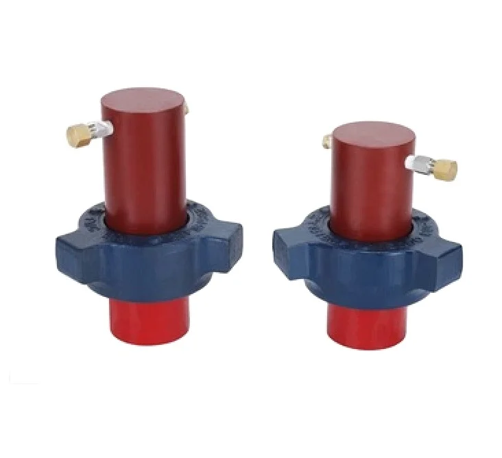
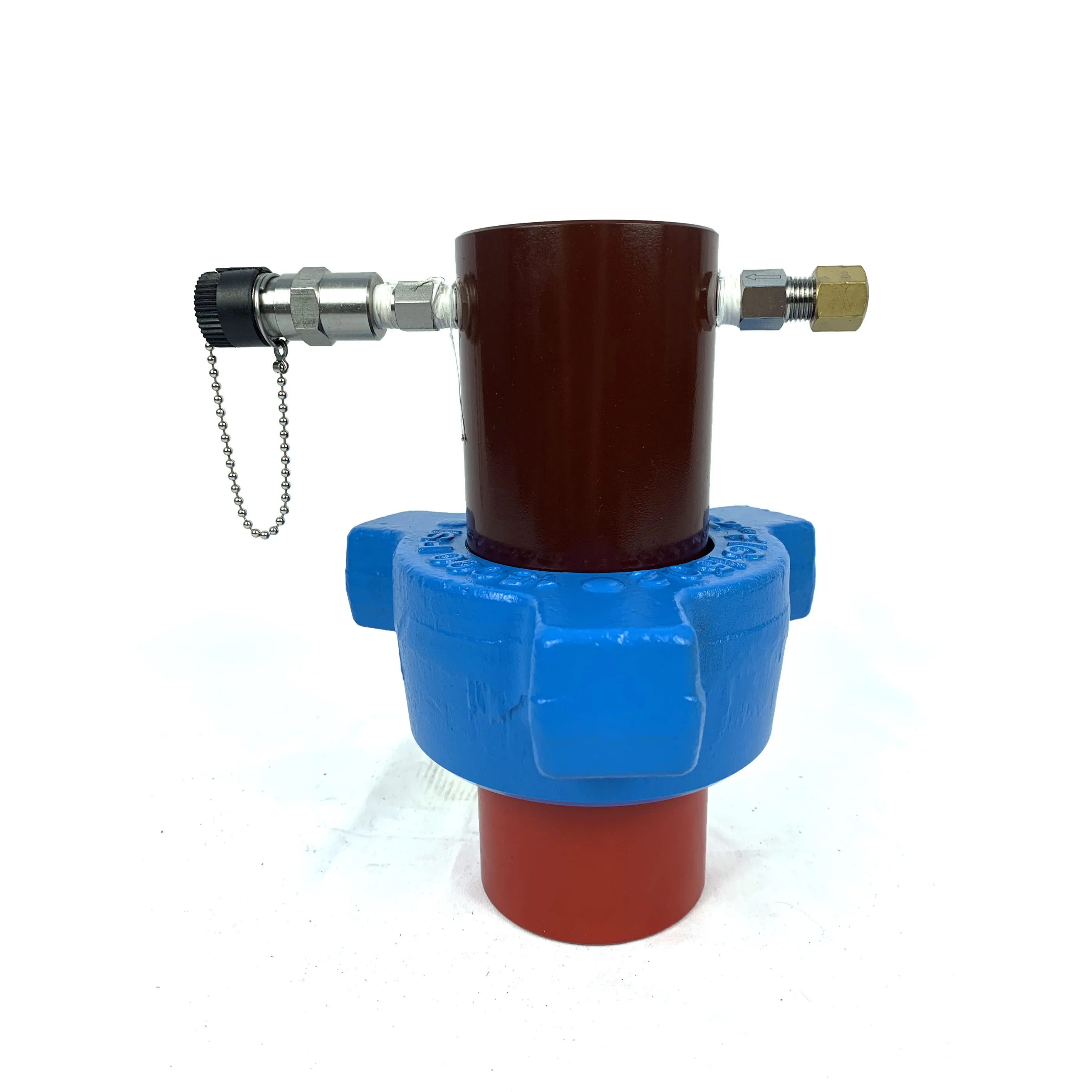
Used primarily for monitoring pump pressures on service trucks engaged in cementing, high pressure hydraulic fracturing operations or acidizing operations involving downhole stimulation of oil pay formations.

Wellbores may be drilled to locate and produce hydrocarbons. Typically, a wellbore is formed by advancing a downhole drilling tool having a drill bit at one end into the ground. As the drilling tool is advanced, drilling mud is pumped from a surface mud pit through a passage or passages in the drilling tool and out the drill bit. The mud exiting the drill bit flows back to the surface to be returned to the mud pit and may be re-circulated through the drilling tool. In this manner, the drilling mud cools the drilling tool, carries cuttings and other debris away from the drilling tool, and deposits the cuttings and other debris in the mud pit. As is known, in addition to the cooling and cleaning operations performed by the mud pumped into the wellbore, the mud forms a mudcake that lines the wellbore which, among other functions, reduces friction between the drill string and subterranean formations.
One known wellbore telemetry system 100 is depicted in FIG. 1. A more detailed description of such a known system is found in U.S. Pat. No. 5,517,464, which is incorporated by reference herein in its entirety. With reference to FIG. 1, a drilling rig 10 includes a drive mechanism 12 to provide a driving torque to a drill string 14. The lower end of the drill string 14 extends into a wellbore 30 and carries a drill bit 16 to drill an underground formation 18. During drilling operations, drilling mud 20 is drawn from a mud pit 22 on a surface 29 via one or more pumps 24 (e.g., reciprocating pumps). The drilling mud 20 is circulated through a mud line 26 down through the drill string 14, through the drill bit 16, and back to the surface 29 via an annulus 28 between the drill string 14 and the wall of the wellbore 30. Upon reaching the surface 29, the drilling mud 20 is discharged through a line 32 into the mud pit 22 so that rock and/or other well debris carried in the mud can settle to the bottom of the mud pit 22 before the drilling mud 20 is recirculated.
As shown in FIG. 1, a downhole measurement while drilling (MWD) tool 34 is incorporated in the drill string 14 near the drill bit 16 for the acquisition and transmission of downhole data or information. The MWD tool 34 includes an electronic sensor package 36 and a mud pulse or mudflow wellbore telemetry device 38. The mudflow telemetry device 38 can selectively block or partially block the passage of the mud 20 through the drill string 14 to cause pressure changes in the mud line 26. In other words, the wellbore telemetry device 38 can be used to modulate the pressure in the mud 20 to transmit data from the sensor package 36 to the surface 29. Modulated changes in pressure are detected by a pressure transducer 40 and a pump piston sensor 42, both of which are coupled to a processor (not shown). The processor interprets the modulated changes in pressure to reconstruct the data collected and sent by the sensor package 36. The modulation and demodulation of a pressure wave are described in detail in commonly assigned U.S. Pat. No. 5,375,098, which is incorporated by reference herein in its entirety.
In addition to the known mud pulse telemetry system 100 depicted in FIG. 1, other wellbore telemetry systems may be used to establish communication between a downhole tool and a surface unit. Examples of known telemetry systems include a wired drill pipe wellbore telemetry system as described in U.S. Pat. No. 6,641,434, an electromagnetic wellbore telemetry system as described in U.S. Pat. No. 5,624,051, an acoustic wellbore telemetry system as described in published PCT Patent Application No. WO2004085796, all of which are hereby incorporated by reference herein in their entireties. Further examples using data conveyance or communication devices (e.g., transceivers coupled to transducers or sensors) have also been used to convey power and/or data between a downhole tool and a surface unit.
Despite the development and advancement of wellbore telemetry devices in wellbore operations, there remains a need for additional reliability and wellbore telemetry capabilities for wellbore operations. As with other many other wellbore devices, wellbore telemetry devices sometimes fail. Additionally, the power provided by many known wellbore telemetry devices may be insufficient to power desired wellbore operations. Attempts have been made to use two different types of mud pulse telemetry devices in a downhole tool. In particular, each of the different mud pulse telemetry devices is typically positioned in the downhole tool and communicatively linked to a different, respective surface unit. Such wellbore telemetry tools have been run simultaneously and non-simultaneously and at different frequencies. Attempts have also been made to develop dual channel downhole wellbore telemetry for transmitting data streams via communication channels to be interpreted independently as described in U.S. Pat. No. 6,909,667. SUMMARY
In accordance with one disclosed example, a method of signal processing that includes providing at least a first pressure sensor and a second pressure sensor spaced in a drilling system and using an algorithm to separate the downwardly propagating waves from the upwardly propagating waves. In one or more examples, an algorithm may include determining a velocity of pressure signals in a wellbore, time-shifting and stacking pressure signals from at least the first pressure sensor and the second pressure sensor to determine a downwardly propagating noise signal, and subtracting the downwardly propagating noise signal from at least the signal from the first pressure sensor.
In accordance with another disclosed example, a wellbore communication system that includes a plurality of pressure sensors spaced within a drilling system along a drilling fluid flow path and communicatively coupled to a surface system and a mud pulse telemetry system positioned within a downhole tool.
In accordance with another disclosed example, a method for wellbore communications that includes obtaining a first corrected pressure signal and a downwardly propagating noise signal from at least a first pressure sensor, computing a cross-correlation function between the first corrected pressure signal and the downwardly propagating noise signal for at least the first pressure sensor, computing the standard deviation of the downwardly propagating noise signal, computing a reflection coefficient for the downwardly propagating noise signal, computing the reflected, upwardly propagating noise signal, and subtracting the upwardly propagating noise signal from the first corrected pressure signal. BRIEF DESCRIPTION OF THE DRAWINGS
FIG. 2 is a schematic view, partially in cross-section, of an example telemetry system including a downhole tool having multiple mud pulse telemetry devices.
FIG. 4 is a schematic view, partially in cross-section, of a yet another example telemetry system including a downhole tool having a mud pulse telemetry device and an electromagnetic wellbore telemetry device.
FIG. 6 is a schematic view of an example drill string telemetry system including an array of pressure transducers to separate downwardly propagating rig noise from upwardly propagating measurement while drilling signals.
FIG. 7 is a cross-sectional view of an example sub that may be used to implement the pressure transducers in the example drill string telemetry system of FIG. 6.
FIG. 12 is a flow chart describing the process for correcting the pressure transducer signals for upwardly propagating mud pump noise that has been reflected by an obstacle in the drill string below the pressure transducer.
One or more example methods and apparatus described below may also utilize drill string telemetry systems and methods that enable the signal-to-noise ratios associated with measurement while drilling signals to be increased. In particular, as described in detail below, one or more pressure sensors or transducers (e.g., an array of pressure transducers) may be disposed (e.g., spaced apart based on a wavelength of a MWD signal) in a portion of a drill string that is composed of wired drill pipe. Pressure signal data collected via the pressure transducers may then be used in conjunction with one or more signal processing techniques to separate, suppress and/or cancel downwardly propagating rig noise (e.g., mud pump generated noise) from upwardly propagating MWD signals (e.g., from a MWD pulser), thereby increasing the signal-to-noise ratio of the MWD signals. In addition, upwardly propagating noise that results from the reflection of downwardly propagating noise can also be separated and removed from the MWD signals.
Referring now to FIG. 2, a mud pulse wellbore telemetry system 200 having multiple telemetry devices is shown. In contrast to the known system 100 of FIG. 1, the example wellbore telemetry system 200 includes two MWD tools 234 aand 234 b,two mud pulse telemetry devices 238 aand 238 b,two transducers 240 aand 240 b,and two sensors 242 aand 242 b.Additionally, the MWD tools 234 aand 238 bmay communicate with a single surface computer or unit 202 via the mud pulse telemetry devices 238 aand 238 b.As can be seen in the example system 200 of FIG. 2, the mud pulse telemetry devices 238 aand 238 bare identical or substantially identical, the MWD tools 234 aand 238 bare identical or substantially identical, and the devices 238 aand 238 band the tools 234 aand 238 bare positioned within a single downhole tool 201 (i.e., the same downhole tool).
Returning in detail to FIG. 2, the MWD tools 234 aand 238 bmay be implemented using the same device(s) used to implement the MWD tool 34 of FIG. 1. Similarly, the mud pulse telemetry devices 238 aand 238 bmay be implemented using the same device(s) used to implement the mud pulse telemetry device 38 of FIG. 1. An example of a mud pulse telemetry device that may be used or otherwise adapted to implement the devices 38, 238 a,and 238 bis described in U.S. Pat. No. 5,517,464, which has previously been incorporated by reference.
In operation, the example wellbore telemetry system 200 of FIG. 2 uses the mud pulse telemetry devices 238 aand 238 bto generate signals (e.g., modulated pressure signals) in the mud 20 flowing in the annulus 28 of the wellbore 30. These generated signals (e.g., modulated or varying pressure signals) may be sensed by one or more of the pressure transducers 240 aand 240 band/or the pressure sensors 242 aand 242 band analyzed by the surface unit 202 to extract or otherwise obtain data or other information relating to the operational condition(s) of the downhole tool 201 (e.g., one or both of the MWD tools 234 aand 238 b), conditions in wellbore 30, and/or any other desired downhole information. In this manner, communications may be established between the downhole tool 201 and, thus, between the MWD tools 234 aand 234 b,and the surface unit 202. More generally, such communications between the downhole tool 201 and the surface unit 202 may be established using uplink and/or downlink systems. Further, while mud pulse telemetry devices 238 aand 238 bare described in connection with the example telemetry system 200 of FIG. 2, other types of wellbore telemetry devices may be employed instead of or in addition to the mud pulse telemetry devices 238 aand 238 b.For example, one or more mud sirens, positive pulse mud flow telemetry devices, and/or negative pulse mud flow telemetry devices may be used.
Turning again to the operation of the example system 200 of FIG. 2, the mud pulse telemetry devices 238 aand 238 bmay send uplink signals (e.g., varying or modulated pressure signals to be conveyed up along through the drill string 14 to the surface 29) by altering the flow of mud through the telemetry devices 238 aand 238 b.Such uplink signals (e.g., varying or modulated pressure signals) are sensed or detected by the pressure transducers 240 aand 240 band/or the pressure sensors 242 aand 242 b.In particular, the uplink signals generated by the telemetry device 238 amay be detected or sensed by the transducer 240 aand/or the pressure sensor 242 a.Similarly, the uplink signals generated by the telemetry device 238 bmay be detected or sensed by the transducer 240 band/or the pressure sensor 242 b.The pressure transducers 240 aand 240 bmay be implemented using devices identical or similar to that used to implement the pressure transducer 40 of FIG. 1, and the sensors 242 aand 242 bmay be implemented using devices identical or similar to that used to implement the sensor 42 of FIG. 1.
FIG. 3 is a schematic view, partially in cross-section, of another example telemetry system 300 including a downhole tool 301 having a wired drill pipe wellbore telemetry system or device 348. In contrast to the known mud pulse telemetry system 100 depicted in FIG. 1, the example telemetry system 300 utilizes a mud pulse telemetry device 338 that is housed in a MWD tool 334 and includes the wired drill pipe telemetry system 348.
As shown in FIG. 3, the MWD tool 334 and the mud pulse telemetry device 338 may be positioned in the downhole tool 301. The MWD tool 334 may be implemented using a device that is similar or identical to that used to implement the MWD tool 34 of the FIG. 1 and/or the MWD tools 234 aand 238 bof FIG. 2. Similarly, the mud pulse telemetry device 338 may be implemented using a device that is similar or identical to that used to implement the mud pulse telemetry device 38 of FIG. 1 and/or the mud pulse telemetry devices 238 aand 238 bof FIG. 2. Additionally, the surface unit or computer 302 may be implemented in a manner similar to the surface unit or computer 202 described in connection with FIG. 2. Thus, the surface unit 302 may be operatively or communicatively coupled to the MWD tool 334 via the mud pulse telemetry device 338 and/or may be operatively or communicatively coupled to the wired drill pipe telemetry system 348 via one or more communication links (not shown). As with the example system 200 of FIG. 2, the surface unit or computer 302 may be proximate the drilling rig 10 or, alternatively, some or all of the surface unit or computer 302 may be remotely located relative to the drilling rig 10.
During operation, either or both of the mud pulse telemetry device 338 and the wired drill pipe system 348 may be used to enable communications between the downhole tool 301 (e.g., the MWD tool 334) and the surface unit 302. Depending on the particular operational mode of the rig 10 and/or downhole or other environmental conditions, the device 338 or the system 348 may be best suited to convey data to the surface unit 302. Alternatively or additionally, both the device 338 and the system 348 may be used to convey information between the surface unit 302 and the downhole tool 301 at the same time. In such a case, the conveyed information may concern the same downhole parameter(s) or condition(s) or different parameter(s) or condition(s).
FIG. 4 is a schematic view, partially in cross-section, of a yet another example telemetry system 400 including a downhole tool 401 having a mud pulse telemetry device 438 and an electromagnetic wellbore telemetry device 448. Similar to the systems 200 and 300 depicted in FIGS. 2 and 3, respectively, the system 400 includes a surface unit or computer 402 that can communicate with the downhole tool 401 and/or other downhole components and analyze information obtained therefrom. In this manner, the surface unit 402 may be operationally or otherwise coupled to a MWD tool 434 via, for example, the mud pulse telemetry device 438. Still further, as with the other systems 200 and 300, the surface unit 402 may be proximate the drilling rig 10 as shown, or some or all of the surface unit 402 may be remotely located relative to the drilling rig 10 and communicatively coupled via, for example, any desired combination of wireless and hardwired communication links to the system 400.
The mud pulse telemetry device 438 is position in the downhole tool 401 and may be implemented using the same device or a device similar to the device used to implement the device 38 of FIG. 1, the devices 238 aand 238 bof FIG. 2, and/or the device 338 of FIG. 3. Also, the MWD tool 434 is positioned in the downhole tool 401 and may be implemented using the same device or a device similar to the device used to implement the device(s) used to implement the tools 234 aand 238 bof FIG. 2, and/or 334 of FIG. 3.
While the example systems depicted in FIGS. 2-4 include certain combinations of mud pulse telemetry, wired drill pipe telemetry, and electromagnetic telemetry systems, other combinations of such systems may be employed to achieve the same or similar results. For example, a wellbore telemetry system using a mud siren, positive and/or negative pulse telemetry devices, an acoustic telemetry device, a tortional wave telemetry device, or any other telemetry device(s) could be used instead of or in addition to those depicted in FIGS. 2-4 to communicate with a surface unit or computer. Additionally, various combinations of communication links (e.g., wireless, hardwired, etc.) may be employed to provide selective communications between the surface unit and the telemetry devices to suit the needs of particular applications.
FIG. 5 is a schematic view, partially in cross-section, of still another example telemetry system 500 including a downhole tool 501 having multiple downhole components and multiple wellbore telemetry devices. As depicted in the example system 500 of FIG. 5, the downhole tool 501 includes two MWD tools 534 aand 534 b,two mud pulse telemetry devices 538 aand 538 b,two pressure transducers 540 aand 540 b,and two sensors 542 aand 542 b.
A surface unit or computer 502, which may be similar or identical to one or more of the example surface units 202, 302, and 402 of FIGS. 2, 3, and 4, respectively, may be communicatively and/or operationally coupled to the telemetry devices 538 aand 538 band/or downhole components 548 aand 548 b.As with the other example surface units 202, 302, and 404, the example surface unit 502 may be proximate (e.g., onsite) or remotely situated (e.g., offsite) relative to the rig 10 and operationally and/or otherwise coupled to the telemetry systems, MWD tools 534 aand 534 b,and/or mud pulse telemetry devices 538 aand 538 bvia any desired communication links (not shown). The MWD tools 534 aand 534 bmay be implemented using devices similar or identical to those used to implement the MWD tools 34, 234 a, 234 b, 334, and/or 434. Similarly, the mud pulse telemetry devices 538 aand 538 bmay be implemented using devices similar or identical to those used to implement the mud pulse telemetry devices 38, 238 a, 238 b, 338, and/or 438.
As depicted in FIG. 5, the downhole tool 501 houses the MWD tools 534 aand 534 b,the mud pulse telemetry devices 538 aand 538 b,and the downhole components 548 aand 548 b.In the example of FIG. 5, the downhole components 548 aand 548 bare depicted as formation evaluation tools, which may be used to test and/or sample fluid from a surrounding formation. Examples of such formation evaluation tools that may be used to implement the tools 548 aand 548 bare described in published U.S. patent application No. 2005/01109538, which is incorporated by reference herein in its entirety. As shown, the downhole components 548 aand 548 binclude stabilizer blades 552 aand 552 bwith probes 554 aand 554 bfor drawing fluid into the downhole tool 501, and backup pistons 550 aand 550 bto assist in driving the probes 554 aand 554 binto position against the wall of the wellbore 30. The formation evaluation components 548 aand 548 bmay enable various pressure testing and/or sampling procedures to be performed. Although the example of FIG. 5 depicts two formation evaluation components in the downhole tool 501, one or more than two formation evaluation components may be used instead.
In the example of FIG. 5, the wellbore telemetry devices 538 aand 538 bare operationally coupled to the respective downhole components 548 aand 548 b.However, one or more wellbore telemetry devices may be coupled to one or more formation evaluation components. For example, two wellbore telemetry devices may be coupled to the same downhole component or, alternatively, each wellbore telemetry device may be coupled to a single, respective downhole component. Additionally, a variety of formation evaluation components may be coupled to one or both of the wellbore telemetry devices 538 aand 538 b.As used herein, “formation evaluation component” refers to a device for performing formation evaluation such as, for example, sampling, detecting formation pressure while drilling, measuring resistivity, nuclear magnetic measurements, or any other downhole tool used to evaluate a subterranean formation.
The separate or individual functionality of the wellbore telemetry devices may also be used to enhance power capabilities needed to perform continuous or additional operations. Multiple wellbore telemetry devices may also be used to increase data transmission rates to the surface and/or to eliminate the need for batteries in the downhole tool. The use of multiple wellbore telemetry devices may also provide a backup system in a case where one of the wellbore telemetry systems fails or is otherwise unable to function properly. Further, in cases where two different wellbore telemetry systems and/or devices are used, alternative types of communications may be employed as desired or needed to provide more effective communications between a downhole tool and a surface unit. Still further, any desired communication medium or combination of media may be used to implement the telemetry systems described herein. For example, any combination of wireless and/or hardwired media may be used to suit the needs of particular applications. More specifically, wireless media may include drilling mud, electromagnetic signals, acoustic signals, etc., and hardwired media may include wired drill pipe and/or any other media using electrical conductors.
As noted above in connection with the examples of FIGS. 2, 3, 4, and 5, the surface units 202, 302, 402, and/or 502 may be located onsite or offsite (e.g., relative to the rig) and may be communicatively and/or operationally coupled to one or more respective downhole tools via communication links (not shown). The communication links may be implemented using any desired wireless and/or hardwired link capable of transmitting data between wellbore telemetry devices and surface units or computers. In some examples, the communication link may be coupled to a wellbore telemetry device via an intermediary device such as, for example, a pressure transducer. The communication link provides means for passing signals such as command, data, power or other signals between the wellbore telemetry devices and the surface computer. These signals may be used to control the downhole tool and/or to retrieve data collected by the downhole tool. Preferably, but not necessarily, signals are passed in real time to provide fast and efficient data collection, tool operation and/or response to wellbore conditions.
The wired drill pipe drill string telemetry system described above (e.g., the example system of FIG. 3) may be used to provide relatively high bandwidth transmission of MWD signals. However, the noise cancellation or suppression systems and methods described below in connection with FIGS. 6-14 can be used with wired drill pipe to improve the signal-to-noise ratio and increase the bandwidth of mud pulse telemetry signals. More specifically, one or more pressure transducers can be distributed or spaced along a section of wired drill pipe in an upper portion of a drill string. The pressure transducers may form a linear array that provides pressure signals that can be processed using vertical seismic profiling techniques such as velocity filtering and stacking as described below to cancel, suppress, or reduce the effects of downwardly propagating noise (e.g., mud pump noise and/or other rig noise) while enhancing upwardly propagating MWD signals (e.g., mud pulse telemetry signals). In addition, the downwardly propagating noise may be reflected from obstacles in the drill string, resulting in upwardly propagating noise. This upwardly propagating noise may also be removed from the MWD signals.
In many MWD operations, especially offshore, the MWD mud pulse telemetry is limited to a very low data rate (<<10 bits/sec). The low data rate results from a low signal-to-noise ratio, which can be caused by high noise levels generated by mud pumps and other rig-based equipment, by mud pump noise in the frequency band of the MWD mud pulse telemetry, and by the exponential attenuation of the MWD signal with depth. The pressure P(Z) measured a distance Z (m) from the mud pulser is attenuated according to P(Z)=P0eZ/Lwhere P0is the pressure at the mud pulser, and where
is an effective length. The inner radius of the drill pipe is a (m); the angular frequency is ω (radians/S); the bulk modulus of the mud is B (Pa); and the viscosity is η (centipose). The attenuation increases with frequency and with the viscosity of the drilling mud. (Reference: New Mud Pulse Telemetry Techniques for Deepwater Applications and Improved Real-Time Data Capabilities, SPE/ADC 67762, R. Hutin et al, 2001). Standard practice is to lower the mud pulse frequency to reduce the attenuation, and/or to shift the mud pulse frequency to avoid frequencies where there is high mud pump noise. In deepwater operations, there may be up to 10,000 feet (3048 m) of cold water between the rig and the seabed. The cold water increases the drilling mud viscosity, which increases the attenuation, and thus further reducing the mud pulse frequency and MWD telemetry data rate.
The systems and methods described below enable a relatively small amount of wired drill pipe (i.e., the entire drill string need not be composed of wired drill pipe) to enable relatively high bandwidth communications using a mud pulse telemetry system. In particular, the noise cancellation, suppression, or reduction systems and methods described herein utilize a relatively small amount of wired drill pipe and pressure transducers to enable a mud pulse telemetry system to communicate effectively at a higher data rate and/or at greater depths, thereby eliminating the need to use wired drill pipe along the entire drill string to achieve a high data rate and/or to communicate at greater depths. This eliminates the need to wire downhole drill string components such as positive displacement motors, jars, and heavy weight drill pipe. Furthermore, by deploying the pressure transducers near the seabed, one avoids the increased attenuation due to the effect of cold seawater on the viscosity of the drilling mud.
FIG. 6 is a schematic view of an example drill string telemetry system 600 including an array of pressure transducers 602, 604, and 606 to cancel, reduce, suppress, or separate downwardly propagating rig noise 608 from an upwardly propagating MWD signal 610. While three pressure transducers 602, 604, and 606 are depicted in the example of FIG. 6, fewer pressure transducers (e.g., one transducer in the wellbore area of the drill string) or more than three pressure transducers may be used instead. However, as described in greater detail below, the use of multiple pressure transducers may result in a greater signal-to-noise ratio for MWD signals generated by a mud pulse telemetry system than possible with, for example, a system employing only one pressure transducer. The example drill string telemetry system 600 includes a drill string 612 that is composed of a wired drill pipe portion 614 and a normal drill pipe portion 616 that is not wired. In the example of FIG. 6, the wired drill pipe portion 614 is located in the upper portion of the drill string 612 and the normal drill pipe portion 616 is located in the lower portion of the drill string 612. The example drill string 612 also includes an MWD telemetry device 618 (e.g., an MWD pulser for mud pulse telemetry) that is adjacent to a bit 620, which is disposed at the bottom end of the example drill string 612.
The pressure transducers 602, 604, and 606, an example implementation of which is depicted and described in connection with FIG. 7, may be spaced apart or separated along the wired drill string portion 614 of the drill string 612 at, for example, intervals preferably about a quarter wavelength of the telemetry signals. For telemetry performed at lower frequencies (e.g., frequencies of a few Hertz), it may be desirable to space the pressure transducers 602, 604, and 606 a hundred or more meters apart, thereby requiring one or more of the pressure transducers 602, 604, and 606 to be located in the borehole. Locating one or more of the pressure transducers 602, 604, and 606 in the borehole increases the distance between the transducers and mud pumps and/or other sources of rig noise, thereby further improving the signal-to-noise ratio of the MWD signal 610.
In general, the use of pressure transducers in connection with MWD mud pulse telemetry systems is known. One such use is described in U.S. Pat. No. 6,741,185, entitled “Digital Signal Receiver for Measurement While Drilling System Having Noise Cancellation,” the entire disclosure of which is incorporated by reference herein. Typically, in contrast to the example system of FIG. 6, these known systems locate one pressure transducer near the mud pump(s), which are primary source of acoustic noise, and another pressure transducer in the standpipe. Thus, both pressure transducers are located relatively close to the source of the rig noise. Signals received from the sensors or transducers are then typically processed or combined to cancel or reduce the effects of the noise signals generated by the mud pump(s). The separation between the transducer located near the mud pump(s) and the transducer in the standpipe affects the degree to which mud pump noise can be canceled or suppressed. A separation of about an eighth of a wavelength (i.e., the wavelength of the mud pulse telemetry signals) or about a quarter of a wavelength is typically used to provide the greatest signal-to-noise ratio for the mud pulse telemetry signals. However, in practice, such separations on the surface near the rig are usually not possible due to the low frequency and long wavelength of the mud pulse telemetry signals and the limited path length associated with the pressure equipment on the rig. Furthermore, pressure transducers 40 are normally located above the rig floor in the mud line 26. Mud pump noise is reflected by the transition from the mud line to drill pipe, which results in complex standing waves that make it difficult to filter the mud pump noise.
In contrast to the known use of pressure transducers noted above, in the example of FIG. 6, the pressure transducers 602, 604, and 606 are located on the drill string 612 in relatively downhole locations, thereby reducing the surface noise to which the sensors 602, 604, and 606 are subjected. The downhole locations of the transducers 602, 604, and 606 and the spacing between the transducers 602, 604, and 606 may be selected based on the acoustic velocity in drilling mud and the frequency at which mud pulse telemetry signals are transmitted by the MWD telemetry device 618. More specifically, the acoustic velocity in drilling mud ranges between about 1 km/sec to 1.5 km/sec, and mud pulse telemetry signals are typically transmitted at a frequency of between about 1 Hz and 24 Hz. The table below provides quarter wavelength sensor spacing in meters for different acoustic velocities and mud pulse telemetry transmission frequencies.
In view of the foregoing quarter wavelength information, a particular example in connection with the example configuration of FIG. 6 is now provided. For example, assume a final bit run begins at a measured depth of 7 kilometers and that the total depth to which the well is to be drilled is 10 kilometers. At the beginning of the final bit run, the MWD telemetry device or pulser 618 may be run into the borehole such that the normal drill pipe 616 is about 6.5 km in length and the wired drill pipe 614 is about 0.5 km in length. Special subs (e.g., the example sub 700 depicted in FIG. 7) containing the pressure transducers 602, 604, and 606, batteries, electronics, processors, communications circuitry, etc. may be uniformly spaced between selected wired drill pipe segments in the wired drill pipe 614 portion of the drill string 612. For example, three such subs could be spaced apart by 250 meters to provide quarter wavelength spacing for 1 Hz MWD signals. The subs (e.g., located at the pressure sensors 602, 604, and 606) can communicate with a surface computer or unit via the communication channel provided by the wired drill pipe 614. In one example, the signals from the pressure transducers 602, 604, and 606 may be sampled and digitized at approximately 200 Hz. The digitized information associated with the transducers 602, 604, and 606 may then be transmitted to a surface computer for further processing via the wired drill pipe 614 or other drill string telemetry (e.g., as described below in connection with FIG. 13). In the example where the drill string telemetry is the wired drill pipe 614, data rates of between about 10 to 50 kbits/sec. are possible, thereby easily accommodating the bandwidth needed to transmit the digitized information.
As drilling continues, an additional 3 km of wired drill pipe 614 is added to reach the total depth of 10 km. In this manner, the distances between the MWD pulser 618 and the pressure transducers 602, 604, and 606 do not increase with drilling. As a result, the signal-to-noise ratio of the MWD signal 610 does not degrade with depth. On the contrary, the signal-to-noise ratio may be increased by adding additional pressure sensors (not shown) to the drill string 612. Additionally, the signal-to-noise ratio improves as the distance between the pressure transducers and surface noise sources increases with depth. In deepwater offshore, the attenuation of the downwardly propagating noise due to the effect of cold water on the drilling mud viscosity is beneficial when the pressure transducers are located near the seabed.
FIG. 7 is a cross-sectional view of an example sub 700 that may be used to implement the pressure transducers 602, 604, and 606 in the example drill string telemetry system 600 of FIG. 6. The example sub 700 includes a collar 702 having a passage 704 through, toroids 706 and 708, electronics 710, batteries 712, and a pressure transducer 714. The sub 700 allows telemetry signals to pass through it, and can itself receive and send telemetry signals. In one example, the toroids 706 and 708 are connected by a wire or other electrical connection. In the example of FIG. 7, the pressure transducer 714 is configured to measure pressure in the interior of the sub 700 (e.g., in the passage 704). However, an annular or exterior pressure measurement could be used instead of or in addition to the interior pressure measurement. The electronics 710, which are powered by the batteries 712, may include interface and signal conditioning circuitry or programming to condition signals received from the pressure transducer 714. The electronics 710 may also include communications circuitry to enable pressure information (e.g., measured pressure values) to be conveyed via the wired drill pipe 614. Specifically, the communications circuitry may be configured to provide varying electrical currents to the toroids 706 and 708 to magnetically couple the pressure signal information to a surface unit (e.g., similar or identical to the surface unit 302 of FIG. 3) via the wires in the wired drill pipe 614. Transformers other than toroids, and/or electrical contacts may be used to connect the sub 700 to the wired drill pipe.
The pressure transducers 602, 604, and 606 of FIG. 6 form an array that may be used to provide a plurality of pressure signals that can be processed to improve the signal-to-noise ratio of the MWD signal 610.


 8613371530291