
mud pump pulsation dampener charge pressure price
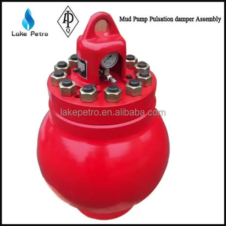
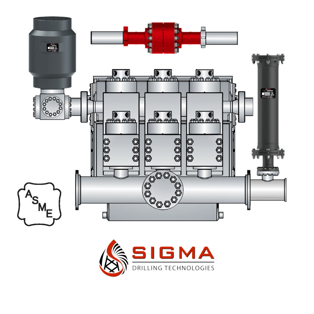
Mud Pump Pulsation Dampener is usually installed on the discharge line to reduce the fluctuation of pressure and displacement of the drilling mud pump.
Mud Pump Pulsation Dampener is a pneumatic device built into the outflow line of each UUD pump to dampen the pressure fluctuations resulting from the action of the pump. Although presented as a surge tank, this device is really a device that can be tuned to greatly diminish the output pulsations transmitted downstream from the mud pump. Unfortunately, the effectiveness of the pulsation dampener is a function of both output pump pressure and frequency of the pump pulsations.
The Charge Free Dampening System™ is the first and only complete dampening system designed for maximum performance and cost savings. With the highest pressure rating at 10,000 psi, the CFD System far surpasses any pulsation control equipment in the drilling market today. Sigma’s system utilizes both appendage and flow-through technologies and yet still maintains the most compact design.
This multistage system utilizes several of Sigma’s advanced products that are proven to maximize efficiencies and upgrade operations of any reciprocating pumping system by themselves.
By protectively coating both inside and outside the system’s Charge Free Stabilizer™ and the Charge Free Dampener™, the system is entirely corrosion-resistant. The Charge Free Dampening System™ is easily the most protected pulsation equipment available.
The advantage of the CFD System’s small size, durability, and performance is combined with the fact the system requires no gas charging. The utilization of the Charge Free Conversion Kit® maximizes the dampening effects of the system without the need for nitrogen charging.
The Charge Free Dampening System™ is categorically the most sophisticated pulsation control available for your rigs’ pumping operations. With the introduction of the CFD System, Sigma Drilling Technologies proves to be the authority on state-of-the-art advancements in pulsation control technologies.

A properly serviced pulsation dampener is critical for your mud pumps’ efficiency, safety, and performance. Unfortunately, there aren’t many resources available to educate personnel on executing safe and effective servicing procedures. Please review the following steps with your personnel for safe pulsation dampener maintenance.
Should you or your personnel have any questions regarding pulsation dampener maintenance, please don’t hesitate to ask. Sigma is more than happy to help you to ensure safe and proper care is being completed on your pulsation dampening equipment.
The pulsation dampeners shall be installed properly to reduce the pressure fluctuation and smooth the liquid flow. In order to extend the lifespan of the air bag, it is highly recommended to maintain the suggested proportion of the pump pressure to the pre-charge pressure of the air bag for the pulsation dampeners. Generally, the pump pressure shall be 2/3 that of the discharge pressure and no more than 4.5MPa.
2. During maintenance, the pump pressure and the pressure inside the pulsation dampeners shall be zero. Since the residual pressure is generally small and can not be indicated on the pressure gauge, user shall confirm the pressure carefully to avoid accident caused by low pressure.
Our custom-designed systems will absorb excess energy pulsing through the pump and piping system by creating a low-pressure area to dampen the excess shocks and vibrations. Because a pulsation dampener regulates the release of energy, your system will be better protected and run more smoothly. After installing a pulsation dampener, customers notice that their system:
Reciprocating pumps emit pulsations into the attached piping systems causing potentially dangerous unbalanced shaking forces, poor valve dynamics, high maintenance costs, and reduced flow. It is well known that gas charged elastomeric bladder or diaphragm pulsation dampeners can be used to effectively reduce the risks of these pulsation induced problems. Gas charged dampeners are relatively compact in size, and are easy to install when compared with maintenance free liquid filled options which tend to be large and more expensive to fabricate.
The potential for the dampener itself to become a vibration problem due to its branch connection being a heavy cantilevered mass having low mechanical natural frequencies.
These drawbacks are common issues for many operators. In a recent brownfield upgrade pump installation, Shell requested that the new pumps include a monitoring system to indicate when the gas charged dampener has failed. Beta Machinery (Beta) were contracted to include this study with the pulsation analysis being performed as per API 674. The hypothesis of the monitoring study was simple: when the dampener fails pulsations increase, an alarm is then triggered indicating a dampener failure.
The test of this hypothesis is presented in the following two-part case study of a brownfield upgrade. In the first part, we will provide the background of the oil company’s experience and the pulsation system model piping design. In next month’s installment, we will examine the complications that arise in a real installation and the challenges to overcome with variable speed pump operation.
Shell’s experience includes numerous reciprocating pumps for glycol and hydrocarbon condensate duties on both manned and unmanned offshore platforms. A majority of the older installations have reciprocating pumps equipped with bladder type pulsation dampeners. There have been numerous technical integrity issues related with the pulsation dampener losing pre-charge frequently, cases with the bladder material rupturing prematurely, and many cases of a notable increase in the vibration of the pump pipework leading to a failure and loss of containment.
With no form of indication available to ascertain the pre-charge pressure, it is difficult if not impossible to determine if the bladder, and/or bladder pressure is intact and holding. The only way to tell if the pulsation dampener is not performing as intended and has lost pre-charge is visual inspection of pipework. When the dampener has lost its pre-charge, the pipe work rattling and high vibration indicates some flaw in the working of the dampener. Under these circumstances the equipment has to be shutdown to manually inspect the dampener, as this has a direct impact on the reliability and downtime of the equipment.
The reciprocating pumps at the Shell Operating Unit facility are not equipped with on-line condition monitoring and the maintenance philosophy revolves around periodic off-line vibration condition monitoring typically carried out using a hand held instrument at three monthly intervals. For unmanned platforms the increase in vibrations are detected when the pump pipework vibration has increased substantially due to loss of pre-charge or the bladder giving away, presenting a high risk threat for operations.
The bladder in the dampener is very sensitive to changes in gas volume. As the line pressure changes, the volume of gas in the bladder changes, thus altering the system performance. The effectiveness of the pulsation dampeners can be reduced by bladder stiffness, bladder permeability, restriction of bladder expansion and contraction by dampener internals and degradation of performance due to large variations in line pressure, making the prediction of dampener performance complicated.
Technical integrity issues with the bladder material rupturing prematurely also surface when technicians charge the pulsation dampeners too quickly, leading to low temperatures at the elastomer interface and cracks propagating through the material. This has the effect of ultimately causing premature failure of the bladder material within a few charges.
Loss of containment through excessive pipe vibration and dampener failure, and the resulting impact on reliability statistics provided the motivation to address some of the issues described above. An opportunity to monitor the technical integrity of pulsation dampeners arose through brownfield project of F13 condensate transfer pumps (Triplex –double diaphragm type) to be installed on the existing E11 PB platform.
In order to address the pulsation dampener integrity issues, a change in the type of dampener from bladder type to the acoustic liquid filled type was considered. This approach was successful only on the greenfield projects. For the brownfield applications this approach met with a limited success considering the fact that space and cost of the liquid filled dampener is much higher than an equivalent gas filled dampener.
The existing piping arrangement is often congested, particularly for offshore facilities, hence the option of installing a liquid filled dampener is effectively ruled out. Moreover most of the pumps within the facility are slow speed with low frequency. Thus this approach was not effective in resolving the brownfield installations.
Metallic bellows type dampeners were next considered for cases where the bladder failed prematurely or failed to hold the pre-charge with the elastomeric element slipping off. This approach did provide some amount of success especially with the high temperature glycol service where the fluid temperature is around 248 degrees Fahrenheit (120 degrees Celsius). The high temperature for the glycol service led to the premature failures of the bladder elastomeric element and cases where the bladder lost its pre-charge within a few days of operation.
Manufacturers of pulsation dampeners were requested to provide some form of indication on the pulsation dampener for ascertaining the pre-charge of nitrogen. Some of the pulsation dampeners complied with this requirement by providing a T-connection with one end of the T connected to a pressure gauge. However, such indication is purely local and is of value only at manned platforms. For the unmanned platforms the issue of pre-charge pressure uncertainty remained.
With appropriate signal conditioning, accelerometers could be used to measure the low frequency and high frequency vibration. Accelerometers mounted on the pump manifolds serve this purpose. The acceleration data can then be used to identify issues with plungers/control rods or valves. However, vibration on the pump piping is generally due to the unbalanced forces in the piping from pulsation, as such measuring vibration would be an indirect method of gauging pulsation. So why not measure pulsation directly?
Based on the limited success with the above approaches, Beta was engaged to work with a manufacturer to provide a solution for triplex pumps to be installed on an unmanned facility. The objective of this exercise was to design an effective and well controlled pulsation system, and at the same time develop a monitoring system capable of detecting the condition of pulsation dampeners and alert operations for any abnormal behavior in the system. It is also to provide some form of assurance to predict the behavior of the dampeners under dynamic variations in the system pressure. F13 condensate transfer pumps were the subject of this approach.
In the second part of this analysis, we will illustrate that the difficulty and risk in maintaining a safe pump system with these dampeners is magnified in offshore and unmanned equipment operations.
Until better options appear on the market to address these important issues, pulsation monitoring is a technique that can be used to monitor dampener integrity. ■
Jordan Grose is the manager of pump systems for Beta Machinery Analysis. Ravindra Pai is a senior rotating engineer at Shell. For more information, visit www.betamachinery.com. This data was presented in an altered form at Dusseldorf’s International Rotating Equipment Conference in 2012.

Pulsation problems often start on the suction side. Pulsation or cavitation is caused by the variation of fluid movement within a contained system. Since fluid is non-compressible, the energy produced by this pulsation or cavitation must be compensated for. With the introduction of pulsation equipment into a system this energy now has a place to expend itself. Without the pulsation equipment involved in your pumping system, the pulsation or cavitation that is present can lead to the following:

A Pulsation Dampener is an inline dampening device used to smooth out pulsations in a pump’s output. They are used alongside a pump as a mounted accessory to help achieve certain flow rates for an application. They can be used with a variety of Positive Displacement Pumps which typically generate a pulsed flow (Diaphragm Pumps, Peristaltic Pumps, Dosing Pumps, Piston Pumps etc)
Pulsation Dampeners are required in some process applications when the customer needs smooth flow into the next phase of the production line, for example, to get an accurate reading through a flow meter or to fill a hopper consistently. On the flip side, Dampeners can be used to reduce water hammer effects through pipework. Water hammer is where the pump causes the pipes to vibrate and potentially fail, a smooth flow from a Pulsation Dampener reduces this.
For example, Diaphragm Pumps inherently produce a very turbulent discharge flow meaning that in some instances a Pulsation Dampeners are required to give a smooth pulse-free flow.
In the Tapflo UK range, we focus on Pulsation Dampeners for Diaphragm and Peristaltic Pumps, although we can also supply them for other pump technologies.
The Active Pulsation Dampener works by supplying an equal pressure to the pulsation supplied by the pump. The Dampener supplies this pressure during the low-pressure points of the pump’s operation, as the pressure drops between pump strokes creating a pulsating flow. The pressure supplied by the dampener decreases pressure variations, therefore producing a steady flow from your Diaphragm Pump. You can see the pressure drops and Pulsation Dampener benefits in action in the diagram below.
Tapflo supplied a 2” Air Operated Diaphragm Pump to a bleach factory, the customer used the T400 PTT for a couple of days and then called us to explain that the bleach line, running along the roof of his production facility, was shaking. Due to the nature of the product being pumped health and safety on site could not allow this to continue.
To support our Peristaltic Pump customers, Tapflo offers an in-line Pulsation Dampener for our PT and PTL Series’. They can reduce the pulsation of your PT Pump by as much as 90% to reduce the vibration and water hammer effects on pipework. Another benefit of this accessory is its ability to be installed on-site horizontally or vertically for flexible installation.
Suction dampener is a very effective aid for improving suction performance and eliminating fluid pulsations in the suction line, which results in a smoother flow in the discharge line.
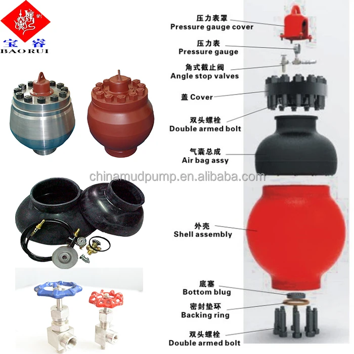
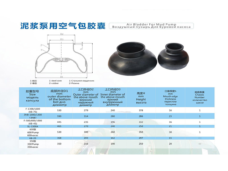
The mounting for KB-75 pulsation dampener (1) is a flange with R-39 seal washer. Before installing dampener, thoroughly clean ring groove and ring, and after setting dampener into place, tighten the nut (8) with 950-1265N.m (700-935ft.lbs) torque. Tighten nuts in a criss-cross order.
The discharge pulsation dampener is only allowed to charge nitrogen or air. No inflammable and explosive gases are allowed such as oxygen, hydrogen etc.

A pulsation dampener reduces or eliminates the variations in pressure and flow produced by reciprocating pumps. In many applications, low frequency pressure waves cause problems within a given piping system and/or process. Eccentric, cam-driven pumps are probably the most commonly applied for services that require pulsation dampening, e.g., metering pumps and reciprocating (power) pumps.
Pulsation dampeners are found in a variety of designs, but for our purposes we will focus on only gas-charged pulsation dampeners, which rely on a calculated volume of compressed gas, usually Nitrogen, which is alternately compressed and expanded in synchronization with the pump plunger to reduce or eliminate pressure pulsations. This gas volume is normally separated from the process fluid by a flexible membrane. Common membrane designs include elastomeric bladders, PTFE diaphragms, PTFE bellows or stainless steel bellows.
Pressure waves or pulses are a consequence of the alternating acceleration and deceleration of fluid velocity corresponding to the travel of the piston or plunger. The pattern and amplitude of these pulses varies with pump configuration, specifically the number and size of pistons, as well as fluid compressibility factors.
It is precisely the fluid volume above mean on the discharge cycle of each stroke, which induces these pressure pulsations into a piping system. The number of pistons offered by the pump—given that all are of identical diameter and equally phased—displace a known peak volume above mean. These constants may be influenced by fluid compressibility, but for the purpose of this explanation we’ll assume none at this point. A pulsation dampener absorbs only that portion of piston displacement above mean flow, and then stores it momentarily before discharging it during the portion of the cycle below mean flow (on the suction stroke).
A simplex pump displaces a volume of fluid above mean that is equal to about 60 percent of total displacement. A duplex pump displaces a lower fluid volume above mean, approximately half that of a simplex pump. Pumps of three or more pistons of equal diameter, stroke length and proportionally phased will always present a very small fluid volume above mean to the piping system. A triplex pump, for example, produces about a 4 percent peak, as long as fluid compressibility factors and pump efficiencies are not at issue.
These smaller fluid volumes are accounted for by the crank angle of each of the cylinders. Triplex pumps are offset by 120-deg. Quadruplex pumps are set apart at 90-deg offsets; quintuplex pumps are offset 72-deg, and so on. It is the resulting overlap in pulses that yield the smaller fluid volumes above mean.
Fluid velocity gradients follow the same mechanical velocity gradients of the eccentric cam that drives the piston(s). Halfway through the piston’s forward travel (discharge stroke), fluid velocity between the discharge check valve and the pulsation dampener begins to decay. The corresponding drop in pressure causes the membrane inside the dampener to expand since the internal gas pre-charge pressure is now higher than the line pressure. The (stored) fluid now being displaced by the pulsation dampener maintains velocity downstream of the dampener thereby reducing, if not eliminating, any downstream pulsations.
Note: A pulsation dampener removes pulses only from the line downstream of the dampener—not upstream. That’s why it’s always recommended that discharge dampeners be installed as close to pump discharge nozzles as possible. In an application of a dampener for suction stabilization (reduction of acceleration head losses), it is the velocity gradient between the supply vessel and the suction nozzle that is minimized.
Let’s begin by defining the pump details required to properly size a pulsation dampener. We will use these values in a sample calculation to help clarify the process.
We recommend that the gas pre-charge pressure be set to 80 percent of system pressure. Lower pre-charge pressures may be specified elsewhere, but our experiences show that this is a low enough pressure to allow the membrane to move freely during operation while maximizing the gas volume. We will use 0.80 in the formula as the “% Pre-Charge” for 80 percent.
The result of the previous calculation is then divided by a constant. As noted previously, the constant is a function of pump configuration. We use a conservative 1.5 for simplex pumps, 2 for duplex pumps, and 7 for triplex pumps. Remember—if the fluid is compressible, then the constant may have to be adjusted downward.
Fluid volumes above mean are well within the range of these constants. The fluid pulse above mean flow from a simplex pump, for example, is about 60 percent. When we divide full stroke displacement by 1.5 the result is a conservative 67 percent. The divisor 7 that we use for triplex pumps allows for a nominal 14 percent fluid volume above mean. While 14 percent is far above the actual 4 percent produced by triplex pumps, the higher volume is an allowance for practical reasons, specifically size and nozzle limits. Otherwise, the result would be a very small dampener relative to pump size.
Ranges of (process) temperature and pressure must be considered in any sizing calculations for pulsation dampeners. Compensations must be made for temperature variations, which affect gas density, and dynamic variations in system pressure, since sizing is based on a set pre-charge pressure.
The objective is to select a dampener that is adequately sized to handle a range of operating pressures with a single pre-charge pressure. Remember that the gas pre-charge pressure should always be based on the minimum operating pressure as the pulsation dampener will have no effect when the system pressure is below the pre-charge pressure.
In instances of either (or both) temperature and pressure variation, we compensate by multiplying the result of our original calculation by the ratio of minimum and maximum temperature and pressure extremes.
Changes in ambient temperature can also influence gas density, but they’re generally disregarded for the purposes of pulsation dampener sizing. It is usually sufficient to make seasonal adjustments to pre-charge pressures, if necessary. Temperature and pressure calculations are recommended to be done using absolute values (Kelvin for temperature and BarA or PSIA for pressure).
Some fluids are highly compressible, such as cryogenics, olefins, liquefied gases, anhydrous ammonia, etc. In these instances, the benefit of lower pulsations from multiple piston pumps may be somewhat compromised. Fluid compression occurs during the leading edge of the (eccentric) crank angle. Given sufficient pressure and a high enough compressibility factor, there may be little or no overlap of pulses at all—in which case, adjustments have to be made and pulsation dampeners with larger gas volumes should be selected.
By installing a properly-sized pulsation dampener, users can reduce or eliminate pipe shake, vibration and noise. The result is a continuous flow of product which is required in many metering, mixing and spraying applications. Reduced pressure pulsations minimize long-term damage to instrumentation and pump components while improving the accuracy of many flowmeters and increasing pump efficiency.


 8613371530291