
mud pump pulsation dampener pre-charge pressure free sample
A properly serviced pulsation dampener is critical for your mud pumps’ efficiency, safety, and performance. Unfortunately, there aren’t many resources available to educate personnel on executing safe and effective servicing procedures. Please review the following steps with your personnel for safe pulsation dampener maintenance.
Should you or your personnel have any questions regarding pulsation dampener maintenance, please don’t hesitate to ask. Sigma is more than happy to help you to ensure safe and proper care is being completed on your pulsation dampening equipment.

At Sigma Drilling Technologies, we utilize out-of-the-box thinking and cutting edge innovation. From our revolutionary pulsation control systems, to our one of a kind performance boosting solutions, Sigma delivers unsurpassed technology. Helping businesses succeed by getting the most out their equipment investment is our goal. Let us partner with your team to help maximize your production output, enhance equipment investment, and place you at the forefront of industry advancements.

A Pulsation Dampener is an inline dampening device used to smooth out pulsations in a pump’s output. They are used alongside a pump as a mounted accessory to help achieve certain flow rates for an application. They can be used with a variety of Positive Displacement Pumps which typically generate a pulsed flow (Diaphragm Pumps, Peristaltic Pumps, Dosing Pumps, Piston Pumps etc)
Pulsation Dampeners are required in some process applications when the customer needs smooth flow into the next phase of the production line, for example, to get an accurate reading through a flow meter or to fill a hopper consistently. On the flip side, Dampeners can be used to reduce water hammer effects through pipework. Water hammer is where the pump causes the pipes to vibrate and potentially fail, a smooth flow from a Pulsation Dampener reduces this.
For example, Diaphragm Pumps inherently produce a very turbulent discharge flow meaning that in some instances a Pulsation Dampeners are required to give a smooth pulse-free flow.
In the Tapflo UK range, we focus on Pulsation Dampeners for Diaphragm and Peristaltic Pumps, although we can also supply them for other pump technologies.
The Active Pulsation Dampener works by supplying an equal pressure to the pulsation supplied by the pump. The Dampener supplies this pressure during the low-pressure points of the pump’s operation, as the pressure drops between pump strokes creating a pulsating flow. The pressure supplied by the dampener decreases pressure variations, therefore producing a steady flow from your Diaphragm Pump. You can see the pressure drops and Pulsation Dampener benefits in action in the diagram below.
Tapflo supplied a 2” Air Operated Diaphragm Pump to a bleach factory, the customer used the T400 PTT for a couple of days and then called us to explain that the bleach line, running along the roof of his production facility, was shaking. Due to the nature of the product being pumped health and safety on site could not allow this to continue.
To support our Peristaltic Pump customers, Tapflo offers an in-line Pulsation Dampener for our PT and PTL Series’. They can reduce the pulsation of your PT Pump by as much as 90% to reduce the vibration and water hammer effects on pipework. Another benefit of this accessory is its ability to be installed on-site horizontally or vertically for flexible installation.

Our custom-designed systems will absorb excess energy pulsing through the pump and piping system by creating a low-pressure area to dampen the excess shocks and vibrations. Because a pulsation dampener regulates the release of energy, your system will be better protected and run more smoothly. After installing a pulsation dampener, customers notice that their system:

This device is designed to reduce pulsations (pressure fluctuations) that occur with systems that have a positive displacement pump. Rubber bladder is pre-charged with nitrogen up to 50-60% of the system pressure. As water passes by the pulsation dampener, it absorbs the pulsations that come from the movement of water in the system. It is designed to protect pump equipment and piping in the system and can reduce pulsations down to 4%.

Southwest Oilfield Products is proud to offer a full line of Pulsation Dampener Solutions. Our PD series dampeners are available in 5, 10 & 20-gallon models and are rated for 5000 or 7500psi. Installed on the mud pump strainers cross, these gas-charged drilling dampeners provide optimum performance and dampening of flow variation pulsations generated by the mud pump. Key features include:
This manual makes recommendations only. The customer is at all times responsible for actualdisassembly, inspection, re-assembly and testing of the pulsation dampener body. Thecustomer is also solely responsible for providing competent and qualified persons; equipmentand facilities to perform such operations; and for workmanship and safety.
Page 2 of 10 Rev DAll Pneumatic Pulsation Control Equipment is designed to Section VIII Division I of the ASMEPressure Vessel Code. Specific certifications are available and are shown below.
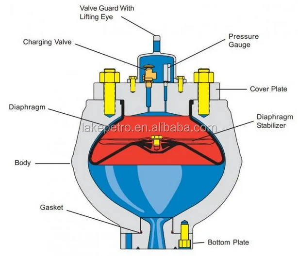
1.1. MOUNTING 1.1.1. The dampener should be mounted as close as possible to the pump for maximum effectiveness. As a general rule, install the dampener within a length not to exceed 10 times the connecting pipe diameter. 1.1.2. Mount the dampener vertically, and if possible in a position where the fluid stream is directed towards the opening in the bottom plate. 1.1.3. The Fluid connection faces should be thoroughly cleaned and the API ring grooves checked for uniform sealing surfaces. 1.1.4. A new API ring should be cleaned, checked and coated with a light coat of grease before being installed in the mounting flange ring groove. 1.1.5. Insert the flange mounting studs into the 8 threaded holes in the bottom plate. All studs should be seated to assure that they are properly inserted. There should be less than 0.25” (6 mm) variation in installed height.
Warning: Safety Hazard Do not lift anything other than the dampener itself with the valve guard/lifting eye or material failure may occur. The valve guard has a lifting capacity of 1.5 times the weight of the dampener in accordance with ASME code.
1.1.6. Install the API ring in the ring groove. Lower the dampener onto the mating flange using the lifting eye on the valve guard. Ensure the space between the flange and bottom connection is equal around the circumference. 1.1.7. Install the nuts and tighten using a cross pattern to the proper torque using the table below. Bolt Size - UNC Lubricated Torque In mm lb.-ft Newton-Meters 0.625 16 130 180 0.750 19 210 280 0.875 22 320 430 1.000 25 460 620 1.125 29 630 850 1.250 32 840 1130 1.375 35 1100 1490 1.500 38 1400 1890 1.625 41 1700 2300 1.750 44 2040 2750 1.875 48 2500 3380 2.000 51 3000 4050 2.250 57 3180 4311
Warning: Safety Hazard Pump must be isolated from inlet and outlet piping and fluid drained before disconnecting any flanges. Always pre-charge with NITROGEN and with ZERO pressure on the system. Using any other gas may cause an explosion and serious injury to personnel.
2.1. GENERAL PRE-CHARGING INSTRUCTIONS 2.1.1. One of the most important factors in proper pulsation dampener performance is the pre- charge pressure. Normally, the pre-charge pressure is based on the average operating pressure of the system. As a general rule, pre-charge the system between 40%-60% of the average operating pressure. For more specific charging instructions, contact a Mattco pulsation control representative. 2.1.2. Pre-charging the dampener is accomplished by using commercially available NITROGEN cylinders. The number of nitrogen cylinders required to pre-charge the bladder will depend on dampener capacity and pre-charge pressure. The chart below is based on the use of STD. 224 cubic feet, 2200 PSI dry nitrogen cylinders.
10 GALLON 20 GALLON Pre-charge No. cylinders Pre-charge No. Cylinders Pressure required Pressure required 1-1100 PSI (1) 0-700 PSI (1) 1100-1600 PSI (2) 700-1300 PSI (2) 1300-1600 PSI (3) For higher pre-charge pressures a gas booster pump (i.e. Haskell International) should be used.
2.1.3. The charging valve and pressure gauge are under the valve guard. The valve guard can be lifted clear by removing four 5/8” bolts securing the valve guard to the upper closure plate. 2.1.4. Before pre-charging, make sure all upper closure plate nuts are secured and evenly tightened. Make sure the charging valve is closed by turning it fully clockwise until it stops. Remove the chained dust cover plug. 2.1.5. Connect the charging hose assembly to the charging valve and the regulator on the nitrogen cylinder. 2.1.6. Slowly open the regulator on the nitrogen cylinder until the recommended pre-charge pressure shows on the gauge. 2.1.7. Slowly open the charging valve on the dampener by turning the valve counter- clockwise. Allow the pressure to build to the proper pre-charge pressure (this may take up to 15 minutes). The regulator pressure and the hose pressure should read the same. Close the charging valve by turning it fully clockwise until it stops. Additional cylinders may be required to bring to proper pressure.
Page 7 of 10 Rev D 2.1.8. Apply soapy water or similar leak detection fluid around the fittings, connections, studs and flange mating areas. Ensure no bubbles are forming which would indicate a leak. In the event of a leak, re-tighten the connections and check again. It is possible reinstallation of the gauge or charging valve may be required to stop a leak. 2.1.9. Once at proper pre-charge pressure, ensure the cylinder regulator and the dampener charging valve are closed. Slowly bleed the pressure from the hose until the hose pressure gauge reads zero. Remove the charging hose assembly and install the charging valve dust cover plug. 2.1.10. Reinstall the valve guard and securely tighten the 5/8” nuts to 130 ft-lbs of torque. Your pulsation dampener is now ready for operation.
2.2. CLEANING AND INSPECTION CYCLE 2.2.1. Monthly inspect the pre-charge pressure on the dampener, or any time the pressure line is showing excess variations. Excessively low pre-charge pressure may indicate a leak or bladder failure. 2.2.2. During routine bladder replacement, inspect the interior of the vessel for any burrs, debris or excess pitting. Mild scale or pitting may be removed with the application of a light emery cloth. If excessive pitting, corrosion or wear is found, contact a MATTCO pulsation control representative. If any problems exist, the other pulsation dampeners should be inspected. Flush the shell before the bladder is reinstalled.
2.3. DIAPHRAGM INSTALLATION 2.3.1. Isolate the pulsation dampener from the pumping system. Ensure the line pressure reads zero. 2.3.2. Remove the valve guard. Remove the dust cover from the charging valve. Turn the charging valve fully counter-clockwise to ensure there is no pre-charge pressure left on the system. Confirm the pressure is zero on the pressure gauge. Reinstall the valve guard. 2.3.3. Loosen the upper closure nuts using a cross pattern. Do not remove the nuts completely until the upper closure plate has been lifted and it has been proven there is no longer a pre-charge on the system. Using a hoist, slowly lift the upper closure plate with the valve guard/lifting eye until the rubber bladder seal has been broken. 2.3.4. Remove the upper closure nuts and remove the upper closure plate. 2.3.5. Remove the existing stabilizer bolt, lock washer, stabilizer plate, and stabilizer. Install a lifting eye into the threaded hole at the bottom of the bladder and remove the existing bladder. 2.3.6. Inspect the bore and gasket sealing areas of the dampener for burrs or nicks. Coat the bore area and the diaphragm with a light coat of grease to aid in installation.
Page 8 of 10 Rev D2.3.7. Pull up on the neck of the bladder while pushing the steel insert at the bottom down, elongating the bladder. Roll the sides of the bladder to form a football shape, using a strap to hold it in this position.2.3.8. Insert the folded diaphragm length-wise into the dampener. Open it up inside the body of the vessel. Adjust the neck of the diaphragm to fit uniformly over the gasket surface of the dampener bore.2.3.9. If required, install the stabilizer, stabilizer plate, lock washer and bolt. Tighten the bolt securely using a socket wrench.2.3.10. Installation of the upper closure plate is the reverse of removal. Be careful when lowering the upper closure plate that the bladder is not crushed or folded over on the bladder sealing surface.2.3.11. Pre-charge the bladder in accordance with section 2.1 of this manual.
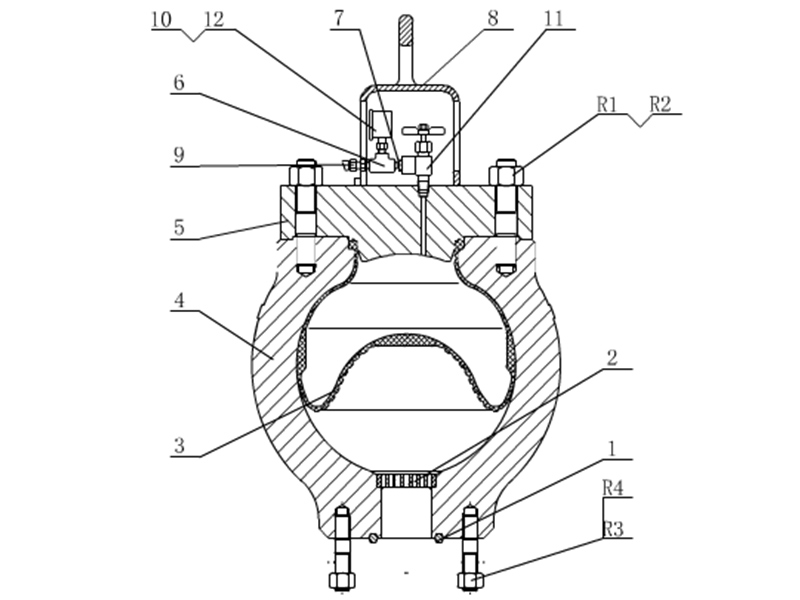
Mud pump pulsation dampeneris the mud pump discharge end main component, installs in the hydraulic end discharge pipe one end, plays the stable pressure and the pressure compensation function, the air bag work pressure is the mud pump work pressure 80%.Attention should be paid to the use of air bag, must be the first pressure relief.The mud pump of F500/F800 USES kb-45 air bag, and the mud pump of F1000/F1300/F1600 USES kb-75 air bag.The middle tie rod produced by our company is made of 35CrMo material, which has a smooth surface after chrome plating and fine grinding, greatly improving the wear resistance and corrosion resistance.
Proper installation and use of pulsation dampener can effectively reduce pressure fluctuations in the discharge system, thus achieving a more uniform fluid flow.In order to achieve a high service life of the air bag, always maintain the recommended ratio between the pump pressure and the air bag precharge pressure (generally not more than 2/3 of the pump discharge pressure, the maximum should not exceed 4.5mpa).
2. In the maintenance of air bag, air bag pressure must be zero, the pump pressure must be zero.Cannot rely on the pressure gauge to judge, because the residual pressure is small, the pressure gauge can not be displayed, but this low pressure will also lead to accidents!


 8613371530291