
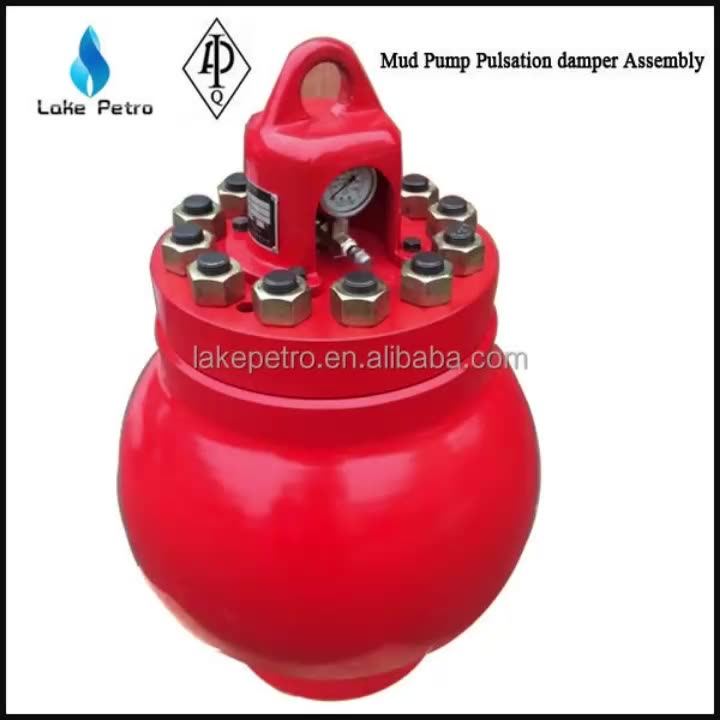
mud pump pulsation damper free sample

At Sigma Drilling Technologies, we utilize out-of-the-box thinking and cutting edge innovation. From our revolutionary pulsation control systems, to our one of a kind performance boosting solutions, Sigma delivers unsurpassed technology. Helping businesses succeed by getting the most out their equipment investment is our goal. Let us partner with your team to help maximize your production output, enhance equipment investment, and place you at the forefront of industry advancements.
The Charge Free Dampening System™ is the first and only complete dampening system designed for maximum performance and cost savings. With the highest pressure rating at 10,000 psi, the CFD System far surpasses any pulsation control equipment in the drilling market today. Sigma’s system utilizes both appendage and flow-through technologies and yet still maintains the most compact design.
This multistage system utilizes several of Sigma’s advanced products that are proven to maximize efficiencies and upgrade operations of any reciprocating pumping system by themselves.
By protectively coating both inside and outside the system’s Charge Free Stabilizer™ and the Charge Free Dampener™, the system is entirely corrosion-resistant. The Charge Free Dampening System™ is easily the most protected pulsation equipment available.
The Charge Free Dampening System™ is categorically the most sophisticated pulsation control available for your rigs’ pumping operations. With the introduction of the CFD System, Sigma Drilling Technologies proves to be the authority on state-of-the-art advancements in pulsation control technologies.

Mud pulsation damper is also called an inflating pump with a suction cup, which is blocked by the rotating piston with a suction cup. The pistonumatic compressed rollers quickly, spray theiquation of the mud into a impurities by flowing into the interior of the vehicle. When the air vaporizes from the suction pipe, the material is removed from the vehicle and into the outlet through the pistonumatic compressed rollers, or known as mud pulsation damper. They are inflated with a pistonumatic compressed rollers, or mud impeller damper, can also be used as a mud suction damper.@@@@@
There are various kinds of mud pumps for sale, such as the mud pulsation damper for sale or a large, mud pulsation damper for sale is a common option in many applications. The pulsation damper for sale is a small, mud pulsation damper that is used for both large and small gears. Mud pulsation damper for sale is a small, self-contained mud pumps that can be used for various purposes, such as shallow mud pumps and farming. There is small mud pulsation damper for sale, and mud pul.

Alibaba.com offers 173 pulsation dampener mud pump products. About 49% % of these are mud pump, 10%% are pumps, and 2%% are other oil field equipments.
A wide variety of pulsation dampener mud pump options are available to you, such as 1 year, not available and 2 years.You can also choose from new, pulsation dampener mud pump,As well as from energy & mining, construction works , and machinery repair shops. and whether pulsation dampener mud pump is 1.5 years, 6 months, or unavailable.
This equipment plays an important role as an accessory to Yamada air-operated double diaphragm pumps. The pulsation dampener serves to reduce pulsation produced in operation and to assure stable discharge flow and pressure.
When pulsations occur with pump operation, it will result in the pressure in Chamber Bbeing greater than that in Chamber A. The diaphragm will act as an air cushion and automatically adjust to this pressure change and absorb the pulsations.
This operation will shift the center rod position upwards and allow more air in Chamber Athrough the air inlet, returning the diaphragm to a neutral position. If liquid pressure decreases, air pressure in Chamber Acauses the diaphragm to move downward, shifting shaft location and changing valve position, releasing excess air pressure in Chamber Awhich returns diaphragm to a neutral position. This action causes a reduction in surges and pulsation caused by a air operated double diaphragm pumps

For more information about pulsation dampeners, we sat down with Brandon Dalrymple and Nathan Ackeret fromBlacoh Fluid Control(manufacturer of pulsation dampeners, surge suppressors, and inlet stabilizers), and asked them to answer a few of our customers’ most common questions about pulsation dampeners.
Pulsation dampeners absorb the energy from the pulse wave created by a positive displacement pump, much like a shock absorber on a vehicle. Absorbing those pulse waves protects pipe welds and supports, and system components from damage due to pressure or excess movement.
A pulsation dampener creates an area of low pressure in the system with enough volume to absorb the pulsation. The pulsation dampener has a membrane with a "cushion" of compressible gas/air behind it that flexes to absorb the pulse, allowing a laminar flow downstream of the dampener.
Pulsation dampeners are commonly used wherever a positive displacement pump discharges flow in an unsteady manner, and where the pulse is not desired for the piping system. Air operated double diaphragm, metering and hose/peristaltic pumps typically benefit from a pulsation dampener.
The type of pulsation dampener used is typically defined by where they are placed in the system, and what they need to do. For example, "pulsation dampeners" are on the downstream side of the pump, "inlet stabilizers" are on the inlet side of the pump, and an accumulator or "surge suppressor" is used next to a valve or other device that restricts the flow in a system.
This video shows where you would place an inlet stabilizer, and how it is used to reduce the pulsation with an air operated diaphragm pump in suction lift conditions.
If you"re experiencing problems with rattling pipes, intermittent flow, water hammer, or pulsations in your system, don"t ignore it. Take the steps necessary to control these symptoms to prevent system deterioration down the road.
Need help with pulsations or water hammer problems? Ask us about it! We gladly provide technical assistance to businesses in Wisconsin and Upper Michigan.
This device is designed to reduce pulsations (pressure fluctuations) that occur with systems that have a positive displacement pump. Rubber bladder is pre-charged with nitrogen up to 50-60% of the system pressure. As water passes by the pulsation dampener, it absorbs the pulsations that come from the movement of water in the system. It is designed to protect pump equipment and piping in the system and can reduce pulsations down to 4%.

A Pulsation Dampener is an inline dampening device used to smooth out pulsations in a pump’s output. They are used alongside a pump as a mounted accessory to help achieve certain flow rates for an application. They can be used with a variety of Positive Displacement Pumps which typically generate a pulsed flow (Diaphragm Pumps, Peristaltic Pumps, Dosing Pumps, Piston Pumps etc)
Pulsation Dampeners are required in some process applications when the customer needs smooth flow into the next phase of the production line, for example, to get an accurate reading through a flow meter or to fill a hopper consistently. On the flip side, Dampeners can be used to reduce water hammer effects through pipework. Water hammer is where the pump causes the pipes to vibrate and potentially fail, a smooth flow from a Pulsation Dampener reduces this.
For example, Diaphragm Pumps inherently produce a very turbulent discharge flow meaning that in some instances a Pulsation Dampeners are required to give a smooth pulse-free flow.
In the Tapflo UK range, we focus on Pulsation Dampeners for Diaphragm and Peristaltic Pumps, although we can also supply them for other pump technologies.
The Active Pulsation Dampener works by supplying an equal pressure to the pulsation supplied by the pump. The Dampener supplies this pressure during the low-pressure points of the pump’s operation, as the pressure drops between pump strokes creating a pulsating flow. The pressure supplied by the dampener decreases pressure variations, therefore producing a steady flow from your Diaphragm Pump. You can see the pressure drops and Pulsation Dampener benefits in action in the diagram below.
Tapflo supplied a 2” Air Operated Diaphragm Pump to a bleach factory, the customer used the T400 PTT for a couple of days and then called us to explain that the bleach line, running along the roof of his production facility, was shaking. Due to the nature of the product being pumped health and safety on site could not allow this to continue.
To support our Peristaltic Pump customers, Tapflo offers an in-line Pulsation Dampener for our PT and PTL Series’. They can reduce the pulsation of your PT Pump by as much as 90% to reduce the vibration and water hammer effects on pipework. Another benefit of this accessory is its ability to be installed on-site horizontally or vertically for flexible installation.

My first days as an MWD field tech I heard horror stories surrounding what is commonly referred to as “pump noise”. I quickly identified the importance of learning to properly identify this “noise”. From the way it was explained to me, this skill might prevent the company you work from losing a job with an exploration company, satisfy your supervisor or even allow you to become regarded as hero within your organization if you’ve proven yourself handy at this skill.
“Pump noise” is a reference to an instability in surface pressure created by the mud pumps on a modern drilling rig, often conflated with any pressure fluctuation at a similar frequency to pulses generated by a mud pulser, but caused by a source external to the mud pulser. This change in pressure is what stands in the way of the decoder properly understanding what the MWD tool is trying to communicate. For the better part of the first year of learning my role I wrongly assumed that all “noise” would be something audible to the human ear, but this is rarely the case.
A mud pulser is a valve that briefly inhibits flow of drilling fluid traveling through the drill string, creating a sharp rise and fall of pressure seen on surface, also known as a “pulse”.
Depending on if the drilling fluid is being circulated in closed or open loop, it will be drawn from a tank or a plastic lined reservoir by a series(or one) mud pumps and channeled into the stand pipe, which runs up the derrick to the Kelly-hose, through the saver sub and down the drill-pipe(drill-string). Through the filter screen past an agitator or exciter, around the MWD tool, through a mud motor and out of the nozzles in the bit. At this point the fluid begins it’s journey back to the drilling rig through the annulus, past the BOP then out of the flow line and either over the shale shakers and/or back in the fluid reservoir.
Developing a firm grasp on these fundamentals were instrumental in my success as a field technician and an effective troubleshooter. As you can tell, there are a lot of components involved in this conduit which a mud pulser telemeters through. The way in which many of these components interact with the drilling fluid can suddenly change in ways that slightly create sharp changes in pressure, often referred to as “noise”. This “noise” creates difficulty for the decoder by suddenly reducing or increasing pressure in a manner that the decoder interprets a pulse. To isolate these issues, you must first acknowledge potential of their existence. I will give few examples of some of these instances below:
Suction screens on intake hoses will occasionally be too large, fail or become unfastened thus allowing large debris in the mud system. Depending on the size of debris and a little bit of luck it can end up in an area that will inhibit flow, circumstantially resulting in a sudden fluctuation of pressure.
This specifically is a term used to refer to the mud motor stator rubber deterioration, tearing into small pieces and passing through the nozzles of the bit. Brief spikes in pressure as chunks of rubber pass through one or more nozzles of the bit can often be wrongly interpreted as pulses.
Sometimes when mud is displaced or a pump suction isn’t completely submerged, tiny air bubbles are introduced into the drilling fluid. Being that air compresses and fluid does not, pulses can be significantly diminished and sometimes non-existent.
As many of you know the downhole mud motor is what enables most drilling rigs to steer a well to a targeted location. The motor generates bit RPM by converting fluid velocity to rotor/bit RPM, otherwise known as hydraulic horsepower. Anything downhole that interacts with the bit will inevitably affect surface pressure. One of the most common is bit weight. As bit weight is increased, so does surface pressure. It’s important to note that consistent weight tends to be helpful to the decoder by increasing the amplitude of pulses, but inconsistent bit weight, depending on frequency of change, can negatively affect decoding. Bit bounce, bit bite and inconsistent weight transfer can all cause pressure oscillation resulting in poor decoding. Improper bit speed or bit type relative to a given formation are other examples of possible culprits as well.
Over time mud pump components wear to the point failure. Pump pistons(swabs), liners, valves and valve seats are all necessary components for generating stable pressure. These are the moving parts on the fluid side of the pump and the most frequent point of failure. Another possible culprit but less common is an inadequately charged pulsation dampener. Deteriorating rubber hoses anywhere in the fluid path, from the mud pump to the saver sub, such as a kelly-hose, can cause an occasional pressure oscillation.
If I could change one thing about today’s directional drilling industry, it would be eliminating the term “pump noise”. The misleading term alone has caused confusion for countless people working on a drilling rig. On the other hand, I’m happy to have learned these lessons the hard way because they seem engrained into my memory. As technology improves, so does the opportunities for MWD technology companies to provide useful solutions. Solutions to aid MWD service providers to properly isolate or overcome the challenges that lead to decoding issues. As an industry we have come a lot further from when I had started, but there is much left to be desired. I’m happy I can use my experiences by contributing to an organization capable of acknowledging and overcoming these obstacles through the development of new technology.
[0001] The present application relates generally to the operation of reciprocating systems and, more specifically, to providing a pump discharge pulsation dampener with dual outlets in such reciprocating systems. BACKGROUND
[0002] Reciprocating systems, such as reciprocating pump systems and similar equipment, operate in many types of cyclic hydraulic applications. For example, reciprocating mud pump systems are used to circulate the mud or drilling fluid on a drilling rig. Pressure peaks accelerate the deterioration of the pump, the pump"s fluid end expendable parts, and equipment downstream from the pump with each subsequent pulsation. Failure to control such pressure peaks and inevitably affect the operating performance and operational life of the pump, pump fluid end expendable parts and all downstream components.
[0003] Pulsation dampeners are typically placed immediately downstream from a reciprocating pump, often with a relative size and configuration proportional to the volume of desired fluid displacement per stroke of the pump and the maximum allotted magnitude of the pressure peaks experienced by the pump system during each pulsation. Pulsation dampeners thus aid in reducing pump loads and minimizing pulsation amplitudes to the pump, the pump"s fluid end expendable parts and to equipment downstream. As a result, pulsation dampeners increase the relative operating performance and life of the pump, the pump"s fluid end expendable parts and any equipment downstream from the pump.
[0004] One type of a conventional pump discharge dampener includes an output tube that is located in the pump dampener outlet. This outlet tube passes from the interior of the pump dampener to the pump dampener outlet. All fluid flow passes through this outlet tube, also known variously as the "pressure drop tube", "pressure drop tube assembly", "choke tube", "choker tube", and other names. Typically, the outlet tube is a single passage tube, which may be either internal or external to a cavity. In essentially equivalent structures, orifice plates are used in lieu of tubes.
[0006] Different inner diameter internal or external pressure drop tubes or orifice plate openings producing different discharge pressure pulse amplitudes are employed in a pump pulsation control reactive discharge dampener. Either both pressure drop tubes/orifice plates may be mounted concurrently on or in the dampener, connected to different discharge pipes used selectively by the operator depending upon the piston or plunger size being employed, or the pressure drop tubes/orifice plates may be interchangeable.
[0009] FIGURE 1 is a cross sectional, somewhat simplified schematic view of a reciprocating pump system employed with a pump pulsation control reactive discharge dampener having two different pressure drop tubes according to an exemplary embodiment of the present disclosure;
[0011] FIGURE 3 is a somewhat simplified schematic view of a pump pulsation control reactive discharge dampener having two different internal pressure drop tubes according to an exemplary embodiment of the present disclosure;
[0012] FIGURE 4 is a somewhat simplified schematic view of a pump pulsation control reactive discharge dampener having two different internal pressure drop tubes according to another embodiment of the present disclosure;
[0013] FIGURE 5 is a somewhat simplified schematic view of a pump pulsation control reactive discharge dampener having interchangeable internal pressure drop tubes according to yet another embodiment of the present disclosure;
[0014] FIGURES 6A through 6F are diagrams illustrating a pump pulsation control reactive discharge dampener having internal pressure drop tubes achieved by fitted sleeves with different internal diameters according to still another embodiment of the present disclosure;
[0017] FIGURES 1 through 12, discussed below, and the various embodiments used to describe the principles of the present disclosure in this patent document are by way of illustration only and should not be construed in any way to limit the scope of the disclosure. Those skilled in the art will understand that the principles of the present disclosure may be implemented in any suitably arranged pump discharge dampener that has an inlet and outlet and uses an outlet tube, pressure drop tube (internal or external) or orifice plate to control or partially control pulsation amplitudes.
[0018] FIGURE 1 is a cross sectional, somewhat simplified schematic view of a reciprocating pump system employing a pump pulsation control reactive discharge dampener having two different pressure drop tubes according to an exemplary embodiment of the present disclosure. Pump system 100 may employ a reciprocating pump of a type well-known and commercially available. The pump within pump system 100 is configured to reciprocate one or more plungers or pistons 101 (only one shown in FIGURE 1) . Each piston or plunger is preferably connected by a suitable rotatable crankshaft or eccentric (not shown) mounted in a suitable "power end" housing 102. Power end housing 102 is connected to a fluid end structure 103 configured to have a separate pumping chamber 104 for each piston or plunger 101. Pumping chamber 104 is exposed to its respective piston or plunger 101. One such chamber 104 is shown in FIGURE 1.
[0019] More specifically, FIGURE 1 depicts a simplified cross- sectional view through a typical pumping chamber 104. Fluid end 103 includes housing 105. Pumping chamber 104 receives fluid from inlet manifold 106 by way of a conventional poppet type inlet or suction valve 107 (only one shown) . Piston or plunger 101
[0020] Those skilled in the art will recognize that the techniques of the present disclosure may be utilized with a wide variety of single and multi-cylinder reciprocating piston or plunger power pumps as well as possibly other types of positive displacement pumps. As in example, the number of cylinders of such pumps may vary substantially between a single cylinder and essentially any number of cylinders or separate pumping chambers. Those skilled in the art will also recognize that the complete structure and operation of a suitable pump system is not depicted or described herein. Instead, for simplicity and clarity, only so much of a pump system as is unique to the present disclosure or necessary for an understanding of the present disclosure is depicted and described.
[0021] Conventional pump systems such as pump 100 shown in FIGURE 1 typically include a discharge dampener system. FIGURE 2 depicts one possible discharge dampener system 200. Discharge dampener system 200 has a body 201 with an interior surface forming a substantially annular interior chamber 202. Discharge dampener system 200 is typically secured to a solid surface, for example, a drill rig floor or pump skid. Discharge dampener system 200 receives and discharges "fluid" (which may be entirely liquid or which may include suspended solids - i.e., a slurry) into external discharge piping 201. Discharge dampener system 200 includes an inlet 203 that is coupled in fluid communication with the discharge manifold 110 of pump system 100 either directly or by intervening piping (not shown) , allowing all pumped fluid to enter discharge dampener system 200, becoming temporarily part of the material filling internal volume of chamber 202. All fluid then exits through internal pressure drop tube assembly 205, which directs pumped fluid into an external discharge piping system 204. Pressure drop tube assembly 205 is a generally T-shaped structure with the wide end outside the body 201 of chamber 202 and the length extending through an orifice in the body 201 into the interior of chamber 202.
[0022] Fluid enters the internal end of pressure drop tube assembly 205 from cavity 202 and passes through pressure drop tube assembly 205, discharging into discharge piping system 204. The pressure drop tube creates a resistance or pressure drop as a result of the fluid entering and passing through the pressure drop tube, which has a smaller inner diameter than the inner diameter of discharge piping system 204. The pressure drop tube 205 dampens or lowers the pulsation amplitudes, and also reduces the higher frequency energies created by the pumping actions. As the flow rate changes, however, the pressure drop tube may in some cases
[0023] Pumping systems may utilize different interchangeable pump pistons (or "plungers") having different displacements, generating different fluid flow rates and pressures, etc. For instance, mud pumps are continually increasing in horsepower and thus can operate with a wide range of piston sizes from 5" in diameter up through 9" in diameter. These piston or plunger size variations produce a wide range of flow rates and discharge pressures. Performance can be significantly improved if the pressure drop tubes are designed to handle narrower ranges of flow rates .
[0024] FIGURE 3 is a somewhat simplified schematic view of a pump pulsation control reactive discharge dampener having two different pressure drop tubes according to an exemplary embodiment of the present disclosure. Discharge dampener 300 has an annular body 301 forming an internal cavity 302 into which fluid from pump system 100 passes via inlet 303. Discharge dampener 300 includes dual pressure drop tubes 304 and 305 with respective inlets 306 and 307 internal to the discharge dampener body 301 and respective outlets 308 and 309 external to the discharge dampener body 301. Pressure drop tubes 304 and 305 have different inside diameters producing different pressure drops. High flow pressure drop tube 304 has an inner diameter that is larger than low flow pressure drop tube 305. This allows the operator to bring two independent discharge pipes (not shown in FIGURE 3) to the two external outlet openings 308 and 309 for the two pressure drop tubes 304 and 305, and to switch between those two discharge pipes (i.e., sealing or closing one and employing the other to carry fluid) depending on the piston or plunger size being employed.
[0025] FIGURE 4 is a somewhat simplified schematic view of a pump pulsation control reactive discharge dampener having two different pressure drop tubes according to another embodiment of the present disclosure. Discharge dampener 400 again includes an annular body 401 forming an interior chamber 402 receiving fluid from pumping system 100 via inlet 403. Discharge dampener 400 also includes dual pressure drop tubes 404 and 405 with respective inlet openings 406 and 407 internal to the body 401 coupled by tubing to respective outlet openings 407 and 408 external to the body 401, and again having different inside diameters producing different pressure drops. Rather than being situated side-by-side with parallel orientation as in the embodiment of FIGURE 3, however, pressure drop tubes 404 and 405 are spaced apart around a periphery of the annulus and oriented at an angle such as 90° (as depicted) or 45°, or other angles as may be needed.
[0026] FIGURE 5 is a somewhat simplified schematic view of a pump pulsation control reactive discharge dampener having interchangeable pressure drop tubes according to yet another embodiment of the present disclosure. Discharge dampener 500 includes an annular body 501 forming an interior chamber 502 fed by an inlet 503. In this embodiment, the body 501 has only one discharge opening receiving only one pressure drop tube at a time, either a large inner diameter pressure drop tube 504 or a small inner diameter pressure drop tube 505. Either tube, when mounted, is secured at the exterior of the outlet opening with the length extending into the interior of body 501.
[0027] FIGURES 6A through 6F are diagrams illustrating a pump pulsation control reactive discharge dampener having internal pressure drop tubes achieved by fitted sleeves with different internal diameters according to still another embodiment of the present disclosure. One improvement of the present disclosure is
[0028] Notably, however, the pressure pulsation dampening provided by an internal pressure drop tube of the type illustrated in FIGURES 2 through 5 is achieved primarily based on the internal diameter of the inlet opening for the pressure drop tube. Accordingly, an annular sleeve of the type described above may alternatively be fitted over the end of the inlet for the pressure drop tube in a manner that modifies the internal diameter of the inlet opening. In this manner, the inner diameter of that opening may be adjusted based on the inner diameter of the sleeve. Illustrated in FIGURE 6A are two pressure drop tubes of the same size having different sleeves 601 and 602 fitted over the inlet openings thereof, with different inner diameters to produce different flow characteristics. Thus, sleeves 601 are configured for use with a high flow rate while sleeves 603, producing a smaller inner diameter opening, are configured for use with a low flow rate. Alternatively, the same pressure drop tube may be fitted with different sleeves 601 and 602 at different times to effect the desired change. The sleeves are secured to the inlet ends of the internal pressure drop tubes in any suitable manner, as illustrated by sleeves 603 and 604 in FIGURE 6B, which do not fit over both the inner and outer sides of the pressure drop tube but instead only overly the inner side and the end. Similarly, sleeves
[0029] The shape of the inner corners of a pressure drop tube inlet can change fluid flow into and through the inlet, and therefore pressure pulsation damping performance. Accordingly, the inner corner or edge of the annulus for any of the sleeves 601 through 607 may be rounded 608, sharp (square) 609 or stepped 610 as depicted in FIGURES 6D through 6F. This can be done regardless of the internal diameter. Sleeves with different inner corner or annular edge profiles may be exchanged during operation to adjust pressure pulsation amplitude dampening performance.
[0030] FIGURE 7 illustrates an alternate embodiment to FIGURE 3. In discharge dampener 700, external pressure drop tubes 704 and 705 are mounted over outlet openings 710 and 711 from the body 701. The inner diameters of pressure drop tubes 704 and 705 are different, providing different pressure pulsation dampening characteristics. The inlet of the pressure drop tube may extend inward or downward into the outlet from body 701 or even into the body 701 itself, or may alternatively be flush with the flange face of the outlet from the body 701, depending on operating requirements. Discharge piping (not shown) may be connected to the ends of external pressure drop tubes 704 and 705 remote from


 8613371530291