
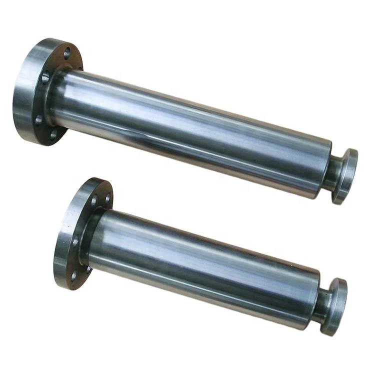
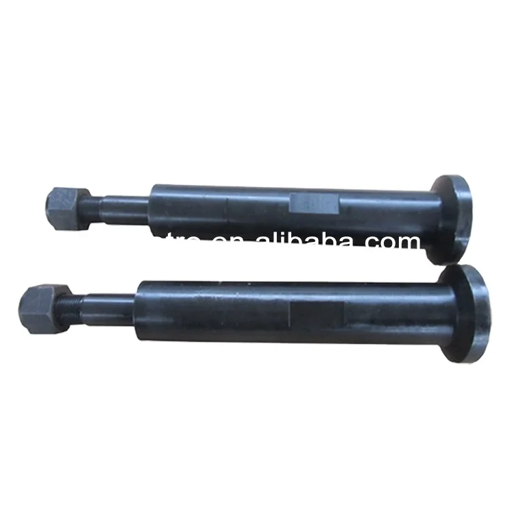
mud pump rod free sample
Created specifically for drilling equipment inspectors and others in the oil and gas industry, the Oil Rig Mud Pump Inspection app allows you to easily document the status and safety of your oil rigs using just a mobile device. Quickly resolve any damage or needed maintenance with photos and GPS locations and sync to the cloud for easy access. The app is completely customizable to fit your inspection needs and works even without an internet signal.Try Template
Fulcrum lets employees on the floor who actually are building the product take ownership. Everyone’s got a smartphone. So now they see an issue and report it so it can be fixed, instead of just ignoring it because that’s the way it’s always been done.
The 2,200-hp mud pump for offshore applications is a single-acting reciprocating triplex mud pump designed for high fluid flow rates, even at low operating speeds, and with a long stroke design. These features reduce the number of load reversals in critical components and increase the life of fluid end parts.
The pump’s critical components are strategically placed to make maintenance and inspection far easier and safer. The two-piece, quick-release piston rod lets you remove the piston without disturbing the liner, minimizing downtime when you’re replacing fluid parts.

Triplex mud pumps pump drilling mud during well operations. An example of a typical triplex mud pump 10 shown in FIG. 1A has a power assembly 12, a crosshead assembly 14, and a fluid assembly 16. Electric motors (not shown) connect to a pinion shaft 30 that drives the power assembly 12. The crosshead assembly 14 converts the rotational movement of the power assembly 12 into reciprocating movement to actuate internal pistons or plungers of the fluid assembly 16. Being triplex, the pump"s fluid assembly 16 has three internal pistons to pump the mud.
As shown in FIG. 1B, the pump"s power assembly 14 has a crankshaft 20 supported at its ends by double roller bearings 22. Positioned along its intermediate extent, the crankshaft 20 has three eccentric sheaves 24-1 . . . 24-3, and three connecting rods 40 mount onto these sheaves 24 with cylindrical roller bearings 26. These connecting rods 40 connect by extension rods (not shown) and the crosshead assembly (14) to the pistons of the pump"s fluid assembly 16.
In addition to the sheaves, the crankshaft 20 also has a bull gear 28 positioned between the second and third sheaves 24-2 and 24-3. The bull gear 28 interfaces with the pinion shaft (30) and drives the crankshaft 20"s rotation. As shown particularly in FIG. 1C, the pinion shaft 30 also mounts in the power assembly 14 with roller bearings 32 supporting its ends. When electric motors couple to the pinion shaft"s ends 34 and rotate the pinion shaft 30, a pinion gear 38 interfacing with the crankshaft"s bull gear 28 drives the crankshaft (20), thereby operating the pistons of the pump"s fluid assembly 16.
When used to pump mud, the triplex mud pump 10 produces flow that varies by approximately 23%. For example, the pump 10 produces a maximum flow level of about 106% during certain crankshaft angles and produces a minimum flow level of 83% during other crankshaft angles, resulting in a total flow variation of 23% as the pump"s pistons are moved in differing exhaust strokes during the crankshaft"s rotation. Because the total flow varies, the pump 10 tends to produce undesirable pressure changes or “noise” in the pumped mud. In turn, this noise interferes with downhole telemetry and other techniques used during measurement-while-drilling (MWD) and logging-while-drilling (LWD) operations.
In contrast to mud pumps, well-service pumps (WSP) are also used during well operations. A well service pump is used to pump fluid at higher pressures than those used to pump mud. Therefore, the well service pumps are typically used to pump high pressure fluid into a well during frac operations or the like. An example of a well-service pump 50 is shown in FIG. 2. Here, the well service pump 50 is a quintuplex well service pump, although triplex well service pumps are also used. The pump 50 has a power assembly 52, a crosshead assembly 54, and a fluid assembly 56. A gear reducer 53 on one side of the pump 50 connects a drive (not shown) to the power assembly 52 to drive the pump 50.
As shown in FIG. 3, the pump"s power assembly 52 has a crankshaft 60 with five crankpins 62 and an internal main bearing sheave 64. The crankpins 62 are offset from the crankshaft 60"s axis of rotation and convert the rotation of the crankshaft 60 in to a reciprocating motion for operating pistons (not shown) in the pump"s fluid assembly 56. Double roller bearings 66 support the crankshaft 60 at both ends of the power assembly 52, and an internal double roller bearing 68 supports the crankshaft 60 at its main bearing sheave 64. One end 61 of the crankshaft 60 extends outside the power assembly 52 for coupling to the gear reducer (53; FIG. 2) and other drive components.
As shown in FIG. 4A, connecting rods 70 connect from the crankpins 62 to pistons or plungers 80 via the crosshead assembly 54. FIG. 4B shows a typical connection of a connecting rod 70 to a crankpin 62 in the well service pump 50. As shown, a bearing cap 74 fits on one side of the crankpin 62 and couples to the profiled end of the connecting rod 70. To reduce friction, the connection uses a sleeve bearing 76 between the rod 70, bearing cap 74, and crankpin 62. From the crankpin 62, the connecting rod 70 connects to a crosshead 55 using a wrist pin 72 as shown in FIG. 4A. The wrist pin 72 allows the connecting rod 70 to pivot with respect to the crosshead 55, which in turn is connected to the plunger 80.
In use, an electric motor or an internal combustion engine (such as a diesel engine) drives the pump 50 by the gear reducer 53. As the crankshaft 60 turns, the crankpins 62 reciprocate the connecting rods 70. Moved by the rods 70, the crossheads 55 reciprocate inside fixed cylinders. In turn, the plunger 80 coupled to the crosshead 55 also reciprocates between suction and power strokes in the fluid assembly 56. Withdrawal of a plunger 80 during a suction stroke pulls fluid into the assembly 56 through the input valve 82 connected to an inlet hose or pipe (not shown). Subsequently pushed during the power stroke, the plunger 80 then forces the fluid under pressure out through the output valve 84 connected to an outlet hose or pipe (not shown).
In contrast to using a crankshaft for a quintuplex well-service pump that has crankpins 62 as discussed above, another type of quintuplex well-service pump uses eccentric sheaves on a direct drive crankshaft. FIG. 4C is an isolated view of such a crankshaft 90 having eccentric sheaves 92-1 . . . 92-5 for use in a quintuplex well-service pump. External main bearings (not shown) support the crankshaft 90 at its ends 96 in the well-service pumps housing (not shown). To drive the crankshaft 90, one end 91 extends beyond the pumps housing for coupling to drive components, such as a gear box. The crankshaft 90 has five eccentric sheaves 92-1 . . . 92-5 for coupling to connecting rods (not shown) with roller bearings. The crankshaft 90 also has two internal main bearing sheaves 94-1, 94-2 for internal main bearings used to support the crankshaft 90 in the pump"s housing.
In the past, quintuplex well-service pumps used for pumping frac fluid or the like have been substituted for mud pumps during drilling operations to pump mud. Unfortunately, the well-service pump has a shorter service life compared to the conventional triplex mud pumps, making use of the well-service pump as a mud pump less desirable in most situations. In addition, a quintuplex well-service pump produces a great deal of white noise that interferes with MWD and LWD operations, further making the pump"s use to pump mud less desirable in most situations. Furthermore, the well-service pump is configured for direct drive by a motor and gear box directly coupling on one end of the crankshaft. This direct coupling limits what drives can be used with the pump. Moreover, the direct drive to the crankshaft can produce various issues with noise, balance, wear, and other associated problems that make use of the well-service pump to pump mud less desirable.
One might expect to provide a quintuplex mud pump by extending the conventional arrangement of a triplex mud pump (e.g., as shown in FIG. 1B) to include components for two additional pistons or plungers. However, the actual design for a quintuplex mud pump is not as easy as extending the conventional arrangement, especially in light of the requirements for a mud pump"s operation such as service life, noise levels, crankshaft deflection, balance, and other considerations. As a result, acceptable implementation of a quintuplex mud pump has not been achieved in the art during the long history of mud pump design.
What is needed is an efficient mud pump that has a long service life and that produces low levels of white noise during operation so as not to interfere with MWD and LWD operations while pumping mud in a well.
A quintuplex mud pump is a continuous duty, reciprocating plunger/piston pump. The mud pump has a crankshaft supported in the pump by external main bearings and uses internal gearing and a pinion shaft to drive the crankshaft. Five eccentric sheaves and two internal main bearing sheaves are provided on the crankshaft. Each of the main bearing sheaves supports the intermediate extent of crankshaft using bearings. One main bearing sheave is disposed between the second and third eccentric sheaves, while the other main bearing sheave is disposed between the third and fourth eccentric sheaves.
One or more bull gears are also provided on the crankshaft, and the pump"s pinion shaft has one or more pinion gears that interface with the one or more bull gears. If one bull gear is used, the interface between the bull and pinion gears can use herringbone or double helical gearing of opposite hand to avoid axial thrust. If two bull gears are used, the interface between the bull and pinion gears can use helical gearing with each having opposite hand to avoid axial thrust. For example, one of two bull gears can be disposed between the first and second eccentric sheaves, while the second bull gear can be disposed between fourth and fifth eccentric sheaves. These bull gears can have opposite hand. The pump"s internal gearing allows the pump to be driven conventionally and packaged in any standard mud pump packaging arrangement. Electric motors (for example, twin motors made by GE) may be used to drive the pump, although the pump"s rated input horsepower may be a factor used to determine the type of motor.
Connecting rods connect to the eccentric sheaves and use roller bearings. During rotation of the crankshaft, these connecting rods transfer the crankshaft"s rotational movement to reciprocating motion of the pistons or plungers in the pump"s fluid assembly. As such, the quintuplex mud pump uses all roller bearings to support its crankshaft and to transfer crankshaft motion to the connecting rods. In this way, the quintuplex mud pump can reduce the white noise typically produced by conventional triplex mud pumps and well service pumps that can interfere with MWD and LWD operations.
Turning to the drawings, a quintuplex mud pump 100 shown in FIGS. 5 and 6A-6B has a power assembly 110, a crosshead assembly 150, and a fluid assembly 170. Twin drives (e.g., electric motors, etc.) couple to ends of the power assembly"s pinion shaft 130 to drive the pump"s power assembly 110. As shown in FIGS. 6A-6B, internal gearing within the power assembly 110 converts the rotation of the pinion shaft 130 to rotation of a crankshaft 120. The gearing uses pinion gears 138 on the pinion shaft 130 that couple to bull gears 128 on the crankshaft 120 and transfer rotation of the pinion shaft 130 to the crankshaft 120.
For support, the crankshaft 120 has external main bearings 122 supporting its ends and two internal main bearings 127 supporting its intermediate extent in the assembly 110. As best shown in FIG. 6A, rotation of the crankshaft 120 reciprocates five independent connecting rods 140. Each of the connecting rods 140 couples to a crosshead 160 of the crosshead assembly 150. In turn, each of the crossheads 160 converts the connecting rod 40"s movement into a reciprocating movement of an intermediate pony rod 166. As it reciprocates, the pony rod 166 drives a coupled piston or plunger (not shown) in the fluid assembly 170 that pumps mud from an intake manifold 192 to an output manifold 198. Being quintuplex, the mud pump 100 has five such pistons movable in the fluid assembly 170 for pumping the mud.
The additional detail of FIG. 8 shows the crankshaft 120 supported in the power assembly 110 and having the connecting rods 140 mounted thereon. As noted above, double roller bearings 122 support the ends of the crankshaft 120 in the assembly 110. Internally, main bearings 123 support the intermediate extent of the crankshaft 120 in the assembly 110. In particular, the main bearings 126 position on the main bearing sheaves 125-1 and 125-2 and are supported by carriers 125 mounted to the assembly 110 at 129. The external main bearings 122 are preferably spherical bearings to better support radial and axial loads. The internal main bearings 125 preferably use cylindrical bearings.
Five connector rods 140 use roller bearings 126 to fit on the eccentric sheaves 124-1 . . . 124-5. Each of the roller bearings 126 preferably uses cylindrical bearings. The rods 140 extend from the sheaves 124-1 . . . 124-5 (perpendicular to the figure) and couple the motion of the crankshaft 120 to the fluid assembly (170) via crossheads (160) as is discussed in more detail below with reference to FIGS. 10A-10B.
The cross-section in FIG. 10A shows a crosshead 160 for the quintuplex mud pump. The end of the connecting rod 140 couples by a wrist pin 142 and bearing 144 to a crosshead body 162 that is movable in a crosshead guide 164. A pony rod 166 coupled to the crosshead body 162 extends through a stuffing box gasket 168 on a diaphragm plate 169. An end of this pony rod 166 in turn couples to additional components of the fluid assembly (170) as discussed below.
The cross-section in FIG. 10B shows portion of the fluid assembly 170 for the quintuplex mud pump. An intermediate rod 172 has a clamp 174 that couples to the pony rod (166; FIG. 10A) from the crosshead assembly 160 of FIG. 10A. The opposite end of the rod 172 couples by another clamp to a piston rod 180 having a piston head 182 on its end. Although a piston arrangement is shown, the fluid assembly 170 can use a plunger or any other equivalent arrangement so that the terms piston and plunger can be used interchangeably herein. Moved by the pony rod (166), the piston head 182 moves in a liner 184 communicating with a fluid passage 190. As the piston 182 moves, it pulls mud from a suction manifold 192 through a suction valve 194 into the passage 190 and pushes the mud in the passage 190 to a discharge manifold 198 through a discharge valve 196.
As noted previously, a triplex mud pump produces a total flow variation of about 23%. Because the present mud pump 100 is quintuplex, the pump 100 offers a lower variation in total flow, making the pump 100 better suited for pumping mud and producing less noise that can interfere with MWD and LWD operations. In particular, the quintuplex mud pump 100 can produce a total flow variation as low as about 7%. For example, the quintuplex mud pump 100 can produce a maximum flow level of about 102% during certain crankshaft angles and can produce a minimum flow level of 95% during other crankshaft angles as the pump"s five pistons move in their differing strokes during the crankshaft"s rotation. Being smoother and closer to ideal, the lower total flow variation of 7% produces less pressure changes or “noise” in the pumped mud that can interfere with MWD and LWD operations.
Although a quintuplex mud pump is described above, it will be appreciated that the teachings of the present disclosure can be applied to multiplex mud pumps having at least more than three eccentric sheaves, connecting rods, and fluid assembly pistons. Preferably, the arrangement involves an odd number of these components so such mud pumps may be septuplex, nonuplex, etc. For example, a septuplex mud pump according to the present disclosure may have seven eccentric sheaves, connecting rods, and fluid assembly pistons with at least two bull gears and at least two bearing sheaves on the crankshaft. The bull gears can be arranged between first and second eccentric sheaves and sixth and seventh eccentric sheaves on the crankshaft. The internal main bearings supporting the crankshaft can be positioned between third and fourth eccentric sheaves and the fourth and fifth eccentric sheaves on the crankshaft.

If you run a mud rig, you have probably figured out that the mud pump is the heart of the rig. Without it, drilling stops. Keeping your pump in good shape is key to productivity. There are some tricks I have learned over the years to keeping a pump running well.
First, you need a baseline to know how well your pump is doing. When it’s freshly rebuilt, it will be at the top efficiency. An easy way to establish this efficiency is to pump through an orifice at a known rate with a known fluid. When I rig up, I hook my water truck to my pump and pump through my mixing hopper at idle. My hopper has a ½-inch nozzle in it, so at idle I see about 80 psi on the pump when it’s fresh. Since I’m pumping clear water at a known rate, I do this on every job.
As time goes on and I drill more hole, and the pump wears, I start seeing a decrease in my initial pressure — 75, then 70, then 65, etc. This tells me I better order parts. Funny thing is, I don’t usually notice it when drilling. After all, I am running it a lot faster, and it’s hard to tell the difference in a few gallons a minute until it really goes south. This method has saved me quite a bit on parts over the years. When the swabs wear they start to leak. This bypass pushes mud around the swab, against the liners, greatly accelerating wear. By changing the swab at the first sign of bypass, I am able to get at least three sets of swabs before I have to change liners. This saves money.
Before I figured this out, I would sometimes have to run swabs to complete failure. (I was just a hand then, so it wasn’t my rig.) When I tore the pump down to put in swabs, lo-and-behold, the liners were cut so badly that they had to be changed too. That is false economy. Clean mud helps too. A desander will pay for itself in pump parts quicker than you think, and make a better hole to boot. Pump rods and packing last longer if they are washed and lubricated. In the oilfield, we use a petroleum-based lube, but that it not a good idea in the water well business. I generally use water and dish soap. Sometimes it tends to foam too much, so I add a few tablets of an over the counter, anti-gas product, like Di-Gel or Gas-Ex, to cut the foaming.
Maintenance on the gear end of your pump is important, too. Maintenance is WAY cheaper than repair. The first, and most important, thing is clean oil. On a duplex pump, there is a packing gland called an oil-stop on the gear end of the rod. This is often overlooked because the pump pumps just as well with a bad oil-stop. But as soon as the fluid end packing starts leaking, it pumps mud and abrasive sand into the gear end. This is a recipe for disaster. Eventually, all gear ends start knocking. The driller should notice this, and start planning. A lot of times, a driller will change the oil and go to a higher viscosity oil, thinking this will help cushion the knock. Wrong. Most smaller duplex pumps are splash lubricated. Thicker oil does not splash as well, and actually starves the bearings of lubrication and accelerates wear. I use 85W90 in my pumps. A thicker 90W140 weight wears them out a lot quicker. You can improve the “climbing” ability of the oil with an additive, like Lucas, if you want. That seems to help.
Outside the pump, but still an important part of the system, is the pop-off, or pressure relief valve. When you plug the bit, or your brother-in-law closes the discharge valve on a running pump, something has to give. Without a good, tested pop-off, the part that fails will be hard to fix, expensive and probably hurt somebody. Pop-off valve are easily overlooked. If you pump cement through your rig pump, it should be a standard part of the cleanup procedure. Remove the shear pin and wash through the valve. In the old days, these valves were made to use a common nail as the shear pin, but now nails come in so many grades that they are no longer a reliable tool. Rated shear pins are available for this. In no case should you ever run an Allen wrench! They are hardened steel and will hurt somebody or destroy your pump.
One last thing that helps pump maintenance is a good pulsation dampener. It should be close to the pump discharge, properly sized and drained after every job. Bet you never thought of that one. If your pump discharge goes straight to the standpipe, when you finish the job your standpipe is still full of fluid. Eventually the pulsation dampener will water-log and become useless. This is hard on the gear end of the pump. Open a valve that drains it at the end of every job. It’ll make your pump run smoother and longer.

The Liberty Process LL8 Progressive Cavity Pump is ideal for abrasive pumping applications such as drilling fluids with sand and grit common in fracking operations. As a Mud Pump, the LL8 Series is a popular model on many mobile pumping rigs in use today. Replacement mud pump parts are available as well from our stock and work on other popular manufacturers models.
The Liberty LL8 is a standard flanged pump design manufactured with cast iron or 316 stainless steel pump casings designed in 1, 2, and 3 stages for 75, 150 and 225 psi discharge pressures and a flow rate of 18 up to 100 GPM.
The LL8 is a modular design with simple hardened pinned joint drive assembly. LL8 Rotors are typically hardened tool steel or 316 stainless steel with a hard chrome plating for long life in abrasive pumping applications.
All other wetted parts are either carbon steel or 316 stainless steel. Stators are available in many elastomer materials such as Buna Nitrile, Natural Rubber, EPDM and Viton. The standard seal design is a set of gland packing with a lantern ring set and flush connections. Mechanical seal options for this progressive cavity pump are readily available.
The LL8 represents one of the most popular progressive cavity pumps available for the transport of drilling mud with easily replaceable in-stock parts.

This section is intended to introduce the reader to various aspects of art that may be related to various aspects of the presently described embodiments. This discussion is believed to be helpful in providing the reader with background information to facilitate a better understanding of the various aspects of the present embodiments. Accordingly, it should be understood that these statements are to be read in this light, and not as admissions of prior art.
In order to meet consumer and industrial demand for natural resources, companies often invest significant amounts of time and money in finding and extracting oil, natural gas, and other subterranean resources from the earth. Particularly, once a desired subterranean resource such as oil or natural gas is discovered, drilling and production systems are often employed to access and extract the resource. These systems may be located onshore or offshore depending on the location of a desired resource. Further, such systems generally include a wellhead assembly mounted on a well through which the resource is accessed or extracted. These wellhead assemblies may include a wide variety of components, such as various casings, valves, pumps, fluid conduits, and the like, that control drilling or extraction operations.
As will be appreciated, drilling and production operations employ fluids referred to as mud or drilling fluids to provide lubrication and cooling of the drill bit, clear away cuttings, and maintain desired hydrostatic pressure during operations. Mud can include all types of water-based, oil-based, or synthetic-based drilling fluids. Mud pumps can be used to move large quantities of mud from surface tanks, down thousands of feet of drill pipe, out nozzles in the bit, back up the annulus, and back to the tanks. Operations come to a halt if the mud pumps fail, and thus, reliability under harsh conditions, using all types of abrasive fluids, is of utmost commercial interest.
Some embodiments of the present disclosure generally relate to a self-aligning mud pump apparatus. In one embodiment, the self-aligning mud pump apparatus includes a housing and a rotatable crankshaft disposed in the housing. The self-aligning mud pump apparatus can include a crosshead disposed in the housing, as well as a crosshead guide disposed in the housing to constrain movement of the crosshead. The self-aligning mud pump apparatus can include a hub disposed in the housing and disposed on the crankshaft for converting a rotating motion of the crankshaft to a reciprocating motion of the crosshead via a connecting rod having a first end coupled to the hub and a second end coupled to the crosshead. The connecting rod can be coupled to the crosshead such that the connecting rod has five degrees of freedom with respect to the crosshead guide.
Certain embodiments of the present disclosure generally relate to a method for assembling self-aligning components of a pump. The method can include providing a crosshead of the pump and coupling a connecting rod to the crosshead with a first socket joint that allows three rotational degrees of freedom between the connecting rod and the crosshead. The method can also include coupling a piston to the crosshead with a second socket joint that allows three rotational degrees of freedom between the piston and the crosshead.
FIG. 6B shows a schematic of an alternative crankshaft of a mud pump such as shown in FIG. 6A in accordance with one or more implementations described herein.
FIG. 6C shows a schematic of an alternative crankshaft of a mud pump such as shown in FIG. 6A in accordance with one or more implementations described herein.
FIG. 7A shows a schematic of a modular mud pump unit that can be used alone or in combination with a mirror-image modular unit, as shown in FIG. 7B, in accordance with one or more implementations described herein.
FIG. 8A shows a partial cross-section of a crosshead and connecting rod interface of a mud pump, in accordance with one or more implementations described herein.
FIG. 8C shows a partial cross-section of a crosshead and connecting rod interface of a mud pump, in accordance with one or more implementations described herein.
When introducing elements of various embodiments, the articles “a,” “an,” “the,” and “said” are intended to mean that there are one or more of the elements. The terms “comprising,” “including,” and “having” are intended to be inclusive and mean that there may be additional elements other than the listed elements. Moreover, any use of “top,” “bottom,” “above,” “below,” other directional terms, and variations of these terms is made for convenience, but does not require any particular orientation of the components.
The present disclosure describes a variety of design changes to mud pump kinematics and construction to result in a less rigid, more robust and reliable mud pump. In a first embodiment described in greater detail below, load balancing is achieved by spacing hubs along the crankshaft of the mud pump with the bull gears disposed opposite one another, on the outermost ends of the crankshaft adjacent to the housing. In such an embodiment, the hubs are disposed along the crankshaft between the bull gears. In a second embodiment described in greater detail below, a novel crosshead design enables connection to both connecting rod and piston, resulting in self-aligning components with at least three degrees of rotational freedom and two degrees of translational freedom. In a third embodiment described in greater detail below, the present disclosure also includes various seal and/or piston sleeve assemblies that can be applied to a plunger style piston.
Generally speaking, FIG. 1 illustrates a wellsite system in which the disclosed mud pump can be employed. The wellsite system of FIG. 1 may be onshore or offshore. In the wellsite system of FIG. 1, a borehole 11 may be formed in subsurface formations by rotary drilling using any suitable technique. A drill string 12 may be suspended within the borehole 11 and may have a bottom hole assembly 100 that includes a drill bit 105 at its lower end. A surface system of the wellsite system of FIG. 1 may include a platform and derrick assembly 10 positioned over the borehole 11, the platform and derrick assembly 10 including a rotary table 16, kelly 17, hook 18 and rotary swivel 19. The drill string 12 may be rotated by the rotary table 16, energized by any suitable means, which engages the kelly 17 at the upper end of the drill string 12. The drill string 12 may be suspended from the hook 18, attached to a traveling block (not shown), through the kelly 17 and the rotary swivel 19, which permits rotation of the drill string 12 relative to the hook 18. A top drive system could alternatively be used, which may be a top drive system well known to those of ordinary skill in the art.
In the wellsite system of FIG. 1, the surface system may also include drilling fluid 26 (also referred to as mud) stored in a pit/tank 27 at the wellsite. A pump 29 supported on a skid 28 may deliver the drilling fluid 26 to the interior of the drill string 12 via a port in the swivel 19, causing the drilling fluid to flow downwardly through the drill string 12 as indicated by the directional arrow 8. The drilling fluid 26 may exit the drill string 12 via ports in a drill bit 105, and circulate upwardly through the annulus region between the outside of the drill string 12 and the wall of the borehole 11, as indicated by the directional arrows 9. In this manner, the drilling fluid 26 lubricates the drill bit 105 and carries formation cuttings up to the surface, as the drilling fluid 26 is returned to the pit/tank 27 for recirculation. The drilling fluid 26 also serves to maintain hydrostatic pressure and prevent well collapse. The drilling fluid 26 may also be used for telemetry purposes. A bottom hole assembly 100 of the wellsite system of FIG. 1 may include logging-while-drilling (LWD) modules 120 and 120A and/or measuring-while-drilling (MWD) modules 130 and 130A, a roto-steerable system and motor 150, and the drill bit 105.
FIG. 2 shows a cutaway side view of a prior art mud pump, illustrating various components of the power assembly, the portion of the pump that converts rotational energy into reciprocating motion. A pump as shown in FIG. 2 could be used as pump 29 of FIG. 1, although many other mud pumps, including those with designs described below in accordance with certain embodiments of the present technique, could instead be used as pump 29. Pinion gears 52 along a pinion shaft 48 drive a larger gear referred to as a bull gear 42 (e.g., a helical gear or a herringbone gear), which rotates on a crankshaft 40. Pinion shaft 48 is turned by a motor (not shown). The crankshaft 40 turns to cause rotational motion of hubs 44 disposed on the crankshaft 40, each hub 44 being connected to or integrated with a connecting rod 46. By way of the connecting rods 46, the rotational motion of the crankshaft 40 (and hub 44 connected thereto) is converted into reciprocating motion. The connecting rods 46 couple to a crosshead 54 (a crosshead block and crosshead extension as shown may be referred to collectively as the crosshead 54 herein). The crosshead 54 moves translationally constrained by guide 57. Pony rods 60 connect the crosshead 54 to a piston 58. In the fluid end of the pump, each piston 58 reciprocates to move mud in and out of valves in the fluid end of the pump 29.
Using conventional mud pump designs, pumping drilling fluids at above 50% capacity and/or for longer periods of time accelerates pump failure. With any combination of the design changes described below implemented, a mud pump may be operable at a higher capacity for longer periods of time. The design changes disclosed herein include load balancing embodiments, self-aligning power assembly embodiments, and piston sealing implementations.
Turning now to FIG. 3, a load-balanced mud pump is shown. Within a housing 33, a pinion shaft 48 is disposed, supported in roller bearings 51 at each opposing end of pinion shaft 48. Pinion shaft 48 is driven by a motor (not shown). A pair of pinion gears 52 rotate on the pinion shaft 48. Pinion gears 52 engage with bull gears 42, each of which rotate on a crankshaft 40. As can be seen in FIG. 3, the bull gears 42 are positioned adjacent to the housing 33 along the crankshaft 40, and pinion gears 52 are likewise positioned adjacent to the housing 33 along the pinion shaft 48. A plurality of hubs 44 are positioned along the crankshaft 40 between the bull gears 42 without any hubs positioned between the bull gears 42 and the walls of the housing 33.
By separating the largest, heaviest gears, i.e., the bull gears 42, toward the exterior along the crankshaft, an optimized load balance is accomplished. The position of the pinion gears 52 being substantially toward the exterior along the pinion shaft 48 further contributes to the load balance of the pump overall. In other embodiments, pinion gears 42 and bull gears 52 may be positioned further away from the walls of the housing while still remaining closer to the walls of the housing than to a midpoint along the pinion shaft 48 and crankshaft 40 respectively.
Each hub 44 is integrated with a connecting rod 46 (typically a forged metal) that couples at an interface to a crosshead 54, which will be discussed in further detail below. In turn, each crosshead 54 also couples at another interface to a plunger piston 58 (shown in FIG. 9A). Crosshead 54 is constrained in direction of movement by a guide, not shown in FIG. 3, discussed further below. In the fluid end, plunger piston 58 draws mud in and out by way of inlet 59 and outlet 61. Valve pots 63 are the machine openings to the fluid end of the mud pump.
FIG. 4A shows a schematic of a mud pump in accordance with one or more implementations described herein. Motors 31 couple operatively to a series of gear wheels 32. The gear wheels 32 rotate the pinion shaft 48. Pinion shaft 48 is supported in the housing 33 by a pinion shaft roller bearing 51 in the wall of housing 33 at either end of the pinion shaft 48. The pinion gears 52 are rotatable on pinion shaft 48. Pinion gears 52 engage bull gears 42, which are rotatable on the crankshaft 40. Crankshaft 40 is supported in the housing 33 on crankshaft roller bearings 56 in the walls of housing 33 at either end of the crankshaft 40. Bull gears 42 are positioned along crankshaft 40 at opposite ends of the crankshaft 40, adjacent to the walls of housing 33. Hubs 44 are positioned along the crankshaft between the bull gears 42. In the embodiment shown, the hubs 44 are spaced about evenly across the crankshaft 40. The crankshaft 40 passes through not the center of each hub, but at a position radially offset from the center of each hub, such that the hubs 44 are out of phase relative to one another to drive the pistons. Alternatively, embodiments are envisioned in which spacing is optimized for load balancing based on the weight and/or size of each individual hub 44 and connecting rod 46. Additionally, four hubs 44 are shown in FIG. 4A, though pumps having as few as two, or as many as five, hubs for driving reciprocal motion of crossheads are likewise contemplated in the present disclosure.
FIG. 4B shows a schematic of an alternative of a mud pump in accordance with one or more implementations described herein. Motors 31 couple operatively to a series of gear wheels 32. The gear wheels 32 rotate two separate pinion shafts, denoted pinion shafts 48A and 48B in FIG. 4B. Separate pinion shafts 48 enable easier repair of pump components, as there is sufficient room to, if needed, remove each pinion shaft independently. By comparison a single longer length pinion shaft may be of such a length as to be physically difficult to remove once the pump is rigged up in limited space at a wellsite. Pinion shafts 48 are supported in the housing 33 by at least a pair of pinion shaft roller bearings 51A and 51B in the wall of housing 33 on both sides of the housing 33. In order for each pinion shaft to rotate without wobbling under weight, at least two points of mechanical support are used. Thus, a mechanical support 55 affixed to (or integrated with) the housing 33 provides support to pairs of roller bearings 51A and 51B. A pinion gear 52 is rotatable on each separate pinion shaft 48. Pinion gears 52 engage bull gears 42, each of which is rotatable on the crankshaft 40. The positioning of the bull gears 42 and hubs 44 along the crankshaft 40 are, in FIG. 4B, similar to the configuration as described with respect to FIG. 4A.
FIG. 4C shows a schematic of an alternative of a mud pump in accordance with one or more implementations described herein. Motors 31 couple operatively to a series of gear wheels 32. The gear wheels 32 rotate two separate pinion shafts 48 coupled together at a coupler 65. The coupler 65 serves two purposes. First, the coupler 65 mechanically fastens the two pinion shafts 48 to one another such that the length of the fastened pinion shafts 48 is mechanically supported. Second, the coupler 65 serves to synchronize rotation of pinion shafts 48A and 48B, allowing the pinion shafts 48A and 48B to be rotated with respect to one another during assembly for proper rotational phase difference between the hubs 44 of the two shafts to drive the pistons. By disconnecting the coupler 65, each pinion shaft 48 can be replaced independent of the other. Pinion shafts 48 are supported in the housing 33 by at least a pair of pinion shaft roller bearings, denoted 51A and 51B, in the wall of housing 33 on both sides of the housing 33. As above, in order for each pinion shaft to rotate without wobbling under weight, at least two points of mechanical support are used. Thus, mechanical support 55 affixed to (or integrated with) the housing 33 provides an anchoring point for pairs of roller bearings 51A and 51B to hold up each pinion shaft 48A and 48B. A pinion gear 52 is rotatable on each separate pinion shaft 48. Pinion gears 52 engage bull gears 42, each of which is rotatable on the crankshaft 40. The positioning of the bull gears 42 and hubs 44 along the crankshaft 40 are, in FIG. 4C, similar to the configuration as described with respect to FIG. 4A.
FIG. 5A shows a schematic of a crankshaft of a mud pump in accordance with one or more implementations described herein. The pinion shaft 48 and pinion gear 52 may be configured as in any of the embodiments described above. As can be seen in FIG. 5A, the bull gears 42 are positioned adjacent to the housing 33 along the crankshaft 40. Pinion gears 52 may likewise be positioned adjacent to the housing 33 along the pinion shaft 48. A plurality of hubs 44 are positioned along the crankshaft 40 between the bull gears 42. An optimized weight load balance is accomplished by separating the largest, heaviest gears, the bull gears 42. In the embodiment of FIG. 5A, the crankshaft 40 spans a length less than the width of the housing 33. In lieu of roller bearings 56 in the walls of the housing 33 to support the crankshaft 40, mechanical supports 62 are attached to (or integrated with) the housing 33 to support the crankshaft 40. Lubricated pads 64 affix to the mechanical supports 62 so that the crankshaft 40 rotates freely. FIG. 5B shows a cross-section of an example of a lubricated pad, as an alternative for a roller bearing, for use in the embodiment shown in FIG. 5A. The lubricated pad 64 may include a lower pad 64A and an upper pad 64B, each conformed to curve around crankshaft 40. In a preferred embodiment, the lubricated pads are offset by 30° relative to a horizontal plane running through the crankshaft 40, as shown. The surface of lower pad 64A and upper pad 64B are lubricated. Additional lubricant can be added to the surfaces in contact with the crankshaft 40 in the gap between lower pad 64A and upper pad 64B.
FIG. 6A shows a schematic of an alternative of a mud pump in accordance with one or more implementations described herein. Load balancing is achieved in the embodiment of FIG. 6A by positioning the bull gears 42 adjacent to one another, centered on the crankshaft 40 and having none of the hubs 44 positioned on the crankshaft 40 therebetween. Motors 31 couple operatively to a series of gear wheels 32. The gear wheels 32 rotate pinion shaft 48. Pinion shaft 48 is supported in the housing 33 by pinion shaft roller bearings 51 in the walls of housing 33 on both sides of the housing 33. Pinion gears 52A and 52B are rotatable on pinion shaft 48, and are positioned adjacent to one another without engaging one another. The pinion gears 52A and 52B may be helical in design, as shown in FIG. 6B. Pinion gears 52 engage bull gears 42, each of which is rotatable on the crankshaft 40. In the embodiment of FIG. 6A, the crankshaft 40 spans a length less than the width of the housing 33. In lieu of roller bearings 56 in the walls of the housing 33 to support the crankshaft 40, mechanical supports 62 are attached to or integrated with the housing 33 to brace or support the crankshaft 40, and lubricated pads 64, such as those shown in FIG. 5B, affix to the mechanical supports 62 such that the crankshaft 40 rotates freely.
In the embodiment shown in FIG. 5A, four hubs 44 are shown, and three mechanical supports 62 are shown between the hubs 44. In the embodiment shown in FIG. 6A, four hubs 44 are shown and four mechanical supports 62 are shown. As with the previously described embodiments, pumps having as few as two, or as many as five, hubs are likewise contemplated in the present disclosure, along with a number of mechanical supports to adequately support the weight of the hubs 44 along the crankshaft 40, as can be readily determined by one of ordinary skill in the art.
FIG. 6C illustrates an alternative embodiment, having bull gears 42 centered along the crankshaft relative to the walls of the housing 33, with hubs 44 disposed along crankshaft 40 axially away from each of the bull gears 42. Mechanical supports 62 extend from the housing 33 to positions between hubs 44. Any numerical combination of hubs and mechanical supports is contemplated by the present disclosure, to the extent that the mechanical supports 62 adequately bear the load of the crankshaft bearing the bull gears 42 and hubs 44. The load is balanced across the length of the crankshaft so as to minimize wobble during high or full capacity usage of the pump.
FIG. 7A shows a schematic of a modular unit that, when coupled with a mirror-image modular unit, is operable as a mud pump in accordance with one or more implementations described herein. By providing independent modules of mud pump power end components, the overall mud pump is scalable. Expensive downtime is reduced with quick repair by interchanging modules, should any component in one module fail. The interchangeable mud pump module shown in FIG. 7A is contained within a housing 33, and a mechanical support 55 is affixed to (or integrated with) the housing 33. A crankshaft 40 is disposed within the housing 33, and a pinion shaft 48 is disposed within the housing 33. A first end of the crankshaft is adapted to couple rotatably to a crankshaft of a second adjacent mud module (which would be coupled at the right side of FIG. 7A). The second end of the crankshaft is rotatably supported in the housing 33, such as by mechanical supports 62 having lubricated pads 64 about the crankshaft 40. As shown, the crankshaft 40 has a plurality of hubs 44 and a bull gear 42 disposed thereon. The bull gear 42 is positioned at the second end of the crankshaft adjacent the housing 33, opposite the end of the crankshaft 40 that is supported in the wall of the housing 33. The mud pump module can also include a rotatable pinion shaft 48 for driving the crankshaft 40. The pinion shaft 48 has disposed thereon a pinion gear 52 engaging the bull gear 42 on the crankshaft 40. When a module such as shown in FIG. 7A is coupled to another that is configured as a mirror image of the one shown in FIG. 7A (as seen in FIG. 7B), a scalable, load-balanced mud pump that is easily repaired is achieved. With a smaller footprint and less weight, substantially less effort is used in rig-up as well. FIG. 7B shows the crankshaft 40 of each module coupled together with a coupler 65. Coupler 65 serves to both provide mechanical strength where the coupler 65 fastens the two crankshafts 40 together, as well as serving to synchronize the rotation thereof, and allow rotation of the crankshafts relative to one another to position each of the hubs 44 properly out of phase with respect to one another for driving the pistons.
A further improvement upon the mud pump design addresses the overall rigidity of the components about the crosshead. When the connection of the connecting rod or piston to the crosshead is not in proper alignment, premature wear may occur on these components, leading to pump failure. By implementing the kinematics of the present disclosure, five degrees of freedom of movement between the connecting rod and the crosshead guide can be achieved: three degrees of rotational freedom and two degrees of translational freedom. Rather than a simple cylindrical pin to couple the connecting rod to the crosshead, the present disclosure envisions a crosshead as shown in FIGS. 8A and 8B having a pin 75A with a spherical main body 75B seated in a bearing to secure the connecting rod within the crosshead block.
FIG. 8A shows a cutaway cross-section of the crosshead and connecting rod interface, in accordance with one or more implementations described herein. In some instances, a crosshead comprises a block that the connecting rod end is inserted into or about, with the connecting rod held rigidly in place by a cylindrical pin through the connecting rod and crosshead. By comparison, the crosshead design of the present disclosure offers additional degrees of freedom of movement. Turning now to FIG. 8A, guides 57 hold the crosshead 54 in place for reciprocating motion. Crosshead 54 comprises a crosshead top 54T, a crosshead bottom 54B, and crosshead side plates 54S. Connecting rod 46 is inserted into the crosshead 54 and secured in place by a pin 75A having a spherical main body 75B. The spherical main body 75B may be integrated with a pin, or a sphere component may be placed about a cylindrical pin. The ends of pin 75A engage with crosshead side plates 54S to hold pin 75A in place while connecting rod 46 is engaged with the cross head 54. A two-piece bearing 76 fastened about the spherical main body 75B of pin 75A facilitates swiveling motion of the connecting rod 46 about the pin 75A. Crosshead side plates 54S secure in place via screws (or like fasteners) through holes 74 in crosshead side plates 54S after the connecting rod 46, bearing 76, and pin 75A are inserted in the crosshead 54. A brace plate 54C provides structural reinforcement to the pin 75A when secured in place to crosshead side plates 54S with fasteners through screw holes 74.
Pin 75A having a spherical main body 75B allows for rotational movement in the RX, RY, and RZdirections (defined with Y-axis in the direction of reciprocal motion into the page), in that connecting rod 46 is free to move rotationally about the spherical main body 75B of the pin 75A. Such freedom of movement is facilitated by bearing 76. FIG. 8B shows a cutaway profile of the crosshead and connecting rod interface of FIG. 8A. As can be seen, the connecting rod 46 includes two apertures, the larger of which is engaged about a hub 44 on the crankshaft 40, and the smaller of which fits into the crosshead 54 that reciprocates through guide 57. Employing the pin 75A having a spherical main body 75B, the connecting rod 46 with bearing 76 is free to swivel about the pin 75A, thereby achieving three degrees of rotational freedom in the RX, RY, and RZdirections.
Turning to FIG. 8B, at least two degrees of translational freedom are achieved between the connecting rod 46 and the crosshead guide 57. Translational movement in the direction TYis the intentional reciprocating movement of the assembly to move the piston. Keys 66 keep crosshead 54 aligned with guide 57 during reciprocating motion. Returning to FIG. 8A, a gap is defined between the crosshead side plates 54S and bearing 76, providing sufficient freedom in the design for translational movement of the connecting rod 46 within the crosshead 54 in the TXdirection along the X-axis. In some embodiments, the spherical main body 75B may slide along pin 75A when the components are physically separate parts; alternatively, in embodiments in which the spherical main body 75B is integral to pin 75A, the pin 75A may be configured to translate along its axis between side plates 54S.
Turning to FIG. 8C, another embodiment demonstrating at least two degrees of translational freedom of the connecting rod 46 with respect to the crosshead guide 57 is shown. Separate pieces of bearing 76 can be seen clearly, providing spherical seating for spherical main body 75B of pin 75A. In assembly, pieces of bearing 76 can be fastened about spherical body 75B of pin 75A (e.g., with a fastener extending through tabs of the bearing 76 and the connecting rod 46, as shown at the top of FIG. 8C). Ends of pin 75A are shown engaged with the crosshead side plates 54S. Variable gaps intentionally imposed between bearing 76 and crosshead side plates 54S, as well as between bearing 76 and connecting rod 46, provide sufficient design latitude for incorporating a degree of mechanical give for translational movement of the connecting rod 46 in the TXdirection, as denoted by the double-sided arrow.
A further improvement upon the mud pump design addresses the issue of seal failure about the piston. In some embodiments of mud pumps, a piston having a moveable sealing head at the fluid end is employed. However, failure of the mud pump occurs when the seal erodes in the harsh working conditions, or when the sealing head fails, such as by breaking off. As an alternative, the present disclosure describes a headless plunger piston having a seal 101 (and optionally sleeve 93) disposed about the piston 58. A variety of means are disclosed for monitoring the seal 101. Additionally, the sleeve 93 may be variable in size depending on the pumping pressure desired in a given application.
Turning now to FIG. 10A, plunger piston 58 is shown in detail, with reciprocating motion in the TYdirection. A directional seal 101 is disposed about the plunger piston 58 on the fluid end. A lubricated pad 94 is provided at the power end of the plunger piston 58, to which oil may be reapplied to lubricate the plunger piston 58. In a cavity 95 defined between the seal 101 and the lubricated pad 94, a drain port 96 may be included so that the quality of the seal 101 at the fluid end can be monitored. As the seal 101 fails, mud will leak in under and around the seal 101, and empty out of the drain port 96.
In an alternative embodiment, as shown in FIG. 10B, a lubricated pad 94 is provided at the power end of the plunger piston 58. Similar to as shown in FIG. 10A, in a cavity 95 formed between the seal 101 and the lubricated pad 94, a drain port 96 may be included so that the quality of the seal 101 at the discharge end can be monitored. Additionally, an injection port 98 to the cavity 95 may be provided such that water can be injected into the cavity to flush any leakage mud out of the drain port 96. In an embodiment, the water may be injected at a relatively low pressure. As the seal 101 fails, mud will leak in under and around the seal, and be forcibly flushed by the injected water out of the drain port 96. The injected water also serves to clean and protect the wetted area of the plunger piston 58.
In an alternative embodiment, as shown in FIG. 10C, a lubricated pad 94 is provided at the power end of the plunger piston 58, as in previous embodiments. An oil port 100 allows lubricant to be added, while an oil drain 102 allows lubricant to flush out, keeping the surface of the piston 58 continually renewed with lubricant. This embodiment is also depicted as having a cavity 95, drain port 96 and injection port 98, as described above. The lubricated pad 94 can be optionally isolated from the area where mud leakage may be present by an additional directional seal 97 that is not in contact with the pressurized mud in the fluid end. The flow and temperature of oil lubricant added may or may not be controlled.
In an alternative embodiment, as shown in FIG. 10D, a lubricated pad 94 is provided at the power end of the plunger piston 58. An oil port 100 allows lubricant to be added through cavity 103 to the lubricated pad 94, while an oil return 104 allows lubricant to circulate, keeping the surface of the plunger piston 58 continually renewed with lubricant. The oil return 104 enables control of the temperature of the lubricant, by inclusion of a heat exchanger 110 to cool the oil. The heat exchanger 110 employed may be of any type familiar to one of ordinary skill in the art. Cavity 95 is defined between seal 101A and an additional directional seal 101B. Additional directional seal 97 prevents oil from entering the fluid end from cavity 103, and mixing with any leaking mud in cavity 95. An injection port 98 to the cavity 95 may be provided such that water can be injected into the cavity 95 to clean the plunger piston 58. In such an embodiment, the water may be injected at a relatively high pressure, in contrast with the low pressure injected water described with respect to FIG. 10C, and forcibly flush leaking fluid from cavity 95. The lubricated pad 94 is thus fluidly isolated from the area around the seal 101 where mud leakage may be present. The embodiment shown in FIG. 10D does not include a drain port 96, but high-pressure water injected into cavity 95 can exit past the seal 101B into the fluid end of the pump.
An alternative embodiment, as shown in FIG. 10E, is similar to that shown in FIG. 10D, but also includes a cavity 99 with a drain port 96. The cavity 99 is provided between the end of the seal 101A and the directional seal 97. The drain port 96 allows the quality of the seals 101 to be monitored. Additionally, the injection port 98 and the cavity 95 between the sealing elements 101A and 101B allow water to be injected into the cavity 95, which can aid the directional seal elements such as 101B in the fluid end by providing resistance to mud leaking under the seal 101B from the working space of the pump.
In embodiments including a drain port 96, as the seals 101 fail, mud may leak and be forcibly flushed out of the drain port 96. Injected water also serves to clean and protect the wetted area of the plunger piston 58. When there is no mud particulate in the flow out of the drain port 96, the seal 101 is in good working condition; however, when there is mud particulate in the flow out of the drain port 96, it is indicative that the seal 101 has begun to fail.
FIG. 10F shows a detailed view of a scraper seal 112 that may be added to the fluid-end side of a seal 101. Scraper seal 112 may be selected from various known geometries of scraper or wiper styles that serve to clean the piston 58 when drawn towards the power-end of the pump.
Additionally, as the plunger piston 58 may be a headless plunger, a sleeve 93 can be disposed about the piston 58. The sleeve 93 may vary in thickness, and be selected to vary the overall effective piston diameter based on desired pressure in the mud pump. The sleeve 93 is disposed about the plunger piston 58 at the fluid end of the plunger piston 58 in fluid communication with the mud. When a sleeve 93 is employed, the seal 101 and lubricating pad 94 are disposed about the sleeve 93 positioned about the piston 58. In each of the embodiments shown in FIGS. 10A-10E, a sleeve 93 can optionally be disposed about the piston to vary piston diameter based on desired pressure in the fluid end of the pump.
FIG. 11A and FIG. 11B show a piston 58 having a sleeve 93 to manipulate the overall effective diameter of the piston 58. As previously stated, changing the diameter of the piston 58 by the addition of sleeve 93 can allow variation of the pressure in the mud pump. For example, FIG. 11A shows a first sleeve 93A that when in place about the piston 58 produces an overall diameter of 5.5 inches (approximately 14 cm). By comparison, FIG. 11B shows a second sleeve embodiment 93B that when in place about the piston 58 produces an overall diameter of 8 inches (approximately 20 cm).
Finally, wear and stress on components of the mud pump can be reduced during start-up of the mud pump. FIG. 12A and FIG. 12B provide schematics of a discharge valve in a fluid end of a mud pump. Without a discharge valve in the fluid end of a mud pump, the pistons are compressing fluid during the start-up of the mud pump, which can create unnecessary overload of the components. In such embodiments, mud pump flow is adjusted by changing the speed of the electrical motor driving the mud pump. By comparison, as can be seen in FIG. 12A, a discharge valve 108 is added to the fluid flow in the fluid end of the mud pump between inlet 59 and outlet 61 (e.g., at the end of a pump liner 115). During start-up of the mud pump, the discharge valve 108 can be opened (for example, by rotation) to provide direct fluid communication between the inlet 59 and the outlet 61. Such free fluid communication reduces the load on components of the mud pump, from electrical motor 31 to piston 58. Additionally, each section of the mud pump can be substantially instantaneously shut down to adjust flow. FIG. 12A shows discharge valve 108 closed with fluid communication blocked indicated by arrow 109. FIG. 12B shows discharge valve 108 open with fluid communication freely flowing indicated at arrow 109.

Whether onshore or offshore, well drilling sites rely on a multitude of systems to successfully perform the drilling operation. The mud pump is a key component tasked with circulating drilling fluid under high pressure downhole. The mud pump can be divided into two key sections: the power end or crosshead and the fluid end. Proper alignment of the pump’s crosshead to the fluid end liner is necessary to maximizing piston and liner life. Misalignment contributes to
accelerated wear on both the piston and the liner, and replacing these components requires downtime of the pump. Traditional methods of inspecting alignment range from using uncalibrated wooden rods, Faro Arms and micrometers to check the vertical and horizontal alignment of the piston rod OD to the piston liner ID. These are time consuming and cumbersome techniques that are ultimately not well suited to troubleshoot and solve alignment issues.
A “Mud Pump Laser Alignment Kit” enables you to measure where the piston will run through the liner at various positions along the pump’s stroke. It will also project a laser centerline from the fluid end back towards the rear power end of the pump that can be used to determine how much shimming is required to correct any alignment issues. The kit can include either a 2-Axis receiver or a 4-Axis which accepts the laser beam and documents where it falls on the active surface of the receiver. The 4-Axis receiver can decrease alignment time by as much as 50% as it will measure angularity as well as X and Y while the 2-Axis does not and will need multiple measurement locations to get the same information. In addition, the alignment system is a non-intrusive service requiring the removal of only the piston rod which allows for much quicker service and less down time on the pump. As the mud pumps in question are located globally both on and offshore, having a small, portable system is another great advantage. Our recommendation would be Pinpoint laser System’s “Mud Pump Alignment Kit”. They are being used by many of the leading repair service companies and have been their main alignment tool for over 15 years. Manufacturers are also utilizing these for new pump set-up.


 8613371530291