
mud pump selection criteria factory
When choosing a size and type of mud pump for your drilling project, there are several factors to consider. These would include not only cost and size of pump that best fits your drilling rig, but also the diameter, depth and hole conditions you are drilling through. I know that this sounds like a lot to consider, but if you are set up the right way before the job starts, you will thank me later.
Recommended practice is to maintain a minimum of 100 to 150 feet per minute of uphole velocity for drill cuttings. Larger diameter wells for irrigation, agriculture or municipalities may violate this rule, because it may not be economically feasible to pump this much mud for the job. Uphole velocity is determined by the flow rate of the mud system, diameter of the borehole and the diameter of the drill pipe. There are many tools, including handbooks, rule of thumb, slide rule calculators and now apps on your handheld device, to calculate velocity. It is always good to remember the time it takes to get the cuttings off the bottom of the well. If you are drilling at 200 feet, then a 100-foot-per-minute velocity means that it would take two minutes to get the cuttings out of the hole. This is always a good reminder of what you are drilling through and how long ago it was that you drilled it. Ground conditions and rock formations are ever changing as you go deeper. Wouldn’t it be nice if they all remained the same?
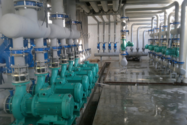
Centrifugal-style mud pumps are very popular in our industry due to their size and weight, as well as flow rate capacity for an affordable price. There are many models and brands out there, and most of them are very good value. How does a centrifugal mud pump work? The rotation of the impeller accelerates the fluid into the volute or diffuser chamber. The added energy from the acceleration increases the velocity and pressure of the fluid. These pumps are known to be very inefficient. This means that it takes more energy to increase the flow and pressure of the fluid when compared to a piston-style pump. However, you have a significant advantage in flow rates from a centrifugal pump versus a piston pump. If you are drilling deeper wells with heavier cuttings, you will be forced at some point to use a piston-style mud pump. They have much higher efficiencies in transferring the input energy into flow and pressure, therefore resulting in much higher pressure capabilities.
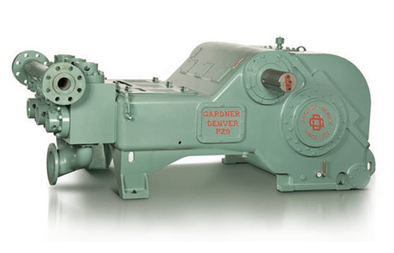
Piston-style mud pumps utilize a piston or plunger that travels back and forth in a chamber known as a cylinder. These pumps are also called “positive displacement” pumps because they literally push the fluid forward. This fluid builds up pressure and forces a spring-loaded valve to open and allow the fluid to escape into the discharge piping of the pump and then down the borehole. Since the expansion process is much smaller (almost insignificant) compared to a centrifugal pump, there is much lower energy loss. Plunger-style pumps can develop upwards of 15,000 psi for well treatments and hydraulic fracturing. Centrifugal pumps, in comparison, usually operate below 300 psi. If you are comparing most drilling pumps, centrifugal pumps operate from 60 to 125 psi and piston pumps operate around 150 to 300 psi. There are many exceptions and special applications for drilling, but these numbers should cover 80 percent of all equipment operating out there.
The restriction of putting a piston-style mud pump onto drilling rigs has always been the physical size and weight to provide adequate flow and pressure to your drilling fluid. Because of this, the industry needed a new solution to this age-old issue.
As the senior design engineer for Ingersoll-Rand’s Deephole Drilling Business Unit, I had the distinct pleasure of working with him and incorporating his Centerline Mud Pump into our drilling rig platforms.
In the late ’90s — and perhaps even earlier — Ingersoll-Rand had tried several times to develop a hydraulic-driven mud pump that would last an acceptable life- and duty-cycle for a well drilling contractor. With all of our resources and design wisdom, we were unable to solve this problem. Not only did Miller provide a solution, thus saving the size and weight of a typical gear-driven mud pump, he also provided a new offering — a mono-cylinder mud pump. This double-acting piston pump provided as much mud flow and pressure as a standard 5 X 6 duplex pump with incredible size and weight savings.
The true innovation was providing the well driller a solution for their mud pump requirements that was the right size and weight to integrate into both existing and new drilling rigs. Regardless of drill rig manufacturer and hydraulic system design, Centerline has provided a mud pump integration on hundreds of customer’s drilling rigs. Both mono-cylinder and duplex-cylinder pumps can fit nicely on the deck, across the frame or even be configured for under-deck mounting. This would not be possible with conventional mud pump designs.
The second generation design for the Centerline Mud Pump is expected later this year, and I believe it will be a true game changer for this industry. It also will open up the application to many other industries that require a heavier-duty cycle for a piston pump application.

(1) The mud pump has advantages of high speed, small size, light weight, high efficiency, high fluidity, simple structure, no pulse infusion, stable performance, easy operation and convenient maintenance.
Therefore, in the following exceptions, centrifugal pumps should be used as much as possible: when metering is required, use a metering pump with high lift requirements; when the flow rate is small and there is no suitable small flow high lift centrifugal pump, a reciprocating pump such as cavitation vortex pump can also be used if the requirements are not high.
Select the pump according to high flow, axial and mixed flow. When the viscosity of the medium is greater than 650 to 1000 square mm/s, select the rotor pump or the reciprocating pump (gear pump, screw pump). In the case of 75% gas medium, if the flow rate is small and the viscosity is less than 37.4 square mm/s, the vortex pump can be used.
In the case of frequent irrigation pumps or inconvenient guidance, self-priming pumps, self-priming centrifugal pumps, self-priming eddy current pumps, and pneumatic (electric) diaphragm pumps should be used.
(2) Make the model and performance of the selected mud pump meet the requirements of technological parameters such as device flow, lift, pressure, temperature, cavitation flow, and suction range.
(3) The dielectric properties that must be met. For the transportation of flammable, toxic or explosive pump medium, it is necessary to have reliable seals for slurry pumps with no leakage, such as magnetic drive pumps, diaphragm pumps, and canned motor pumps.
For delivery pumps of corrosive media, the convection part requires corrosion-resistant materials, such as stainless steel corrosion pumps AFB, the CQF plastic magnetic drive pumps.
A pump for conveying solid particles containing medium, wear-resistant materials requires a convection section. If necessary, seal and rinse it with the cleaning liquid.
(1) Packing is a common seal. The seal is injected with water in the form of continuous injection water under the pressure in the gasket to prevent the leakage of the mud pump. It is not suitable for the seal of multi-stage shaft seal mud pumps and packing. It has advantages of simple packaging and sealing structure, easy maintenance and low price.
(2) The impeller is sealed by the mud pump. The impeller with the reverse centrifugal generates the acting force to prevent the slurry from leaking out.
When the positive pressure value at the pump inlet is not greater than 10% of the pressure value at the outlet of the mud pump, the first-stage pump of a single-stage pump or a multi-stage pump can be designed with an impeller mechanical shaft seal, which does not dilute the slurry and has a good sealing effect.
(3) Mechanical seals of mud pumps generally have relatively high requirements for seals. Especially in some chemical and food fields, not only sealing is required, but it is important not to add additional components to the pump body. The disadvantage is that the mechanical seal of the mud pump is expensive and difficult to maintain.

They are basically generalists, having learned to rely on qualified suppliers, who are experts within their particular niche (pumps, centrifuges, boilers, generators, etc.). When a pump fails, it is usually replaced with a new one, without much analysis or discussion. If it continues to fail frequently, a new supplier is approached for a better, more reliable pump.
So, how is a pumping system, simple or complex, actually designed? Details of pump performance curves, types, pressure, power or efficiency are usually not on the horizon at this initial stage.
All the plant knows is their requirements. Maybe they want to pump 1,000 gallons per minute (gpm) from a cold water tank 2 miles away to a heat exchanger and return the water to the tank. Thus, the details of the pump will start to emerge.
Plug the numbers into pump-magazine.com/pump_magazine/pump_magazine.htm (See Image 2). The actual efficiency predicted by the program is 81.2 percent, better than our estimated 70 percent, and the motor could be smaller. However, also consider that the pump might “run out” on the curve some times when the flow is greater. So a slightly higher value on the motor horsepower would be prudent.
Now we need to refine our selection by the pump type, number of stages, speed of the motor (which may change overall size and efficiency) net positive suction head (NPSH) requirements, etc. But that is for the next time.

Generally those that are most frequently employed for use in sludge pumping activities include progressive cavity, plunger and diaphragm pumps. Each type offers own advantages depending on the application or needs and that includes the concentration of sludge which we are dealing with as well. At times, selection criteria can be complicated due to the fact that certain sludge has variable thickness generated at different intervals depending on the wastewater plant process control.
Progressive Cavity is usually selected based on the requirements and needs on having a more easily controlled pumping flow rates and also in terms of ease of use and simple operations. Progressive cavity pump is considered a self-priming type due to the fact that it is made up of just a single threaded rotor operating in helix stator made up of rubber. The pump must not be operated dry or else the rubber might burn out and replacing a new unit means a heavy disruption to the wastewater treatment operation. Apart from that, the pump can also frequently breakdown and encounter leakages coming from wear and tear happening at the rotors side and replacing a new one will be quite expensive if there is no spare part from the manufacturer. Otherwise, with available capacity that stretches up to 75liters per second, this is usually more than sufficient for a normal sludge transferring process.
Due to the grittiness of incoming sludge, sometimes plant operators would rather opt for plunger pumps. There are many advantages associated with using this type of unit mainly is because the pulsating effect will lead to more concentrated sludge buildup in the hopper after the pumps. When operating under low velocities, it can also help to resuspend the solids in pipelines and with high discharge heads depending on model from manufacturers; it can create discharge head of up to 3 meters. Needs on having adjusted flow and speed control can also be enhanced by using a variable pitch drive belts put into it. Overall, similar like progressive cavity pumps, plunger types are also self-priming which means that it will avoid the hassle that usually comes about when it comes to sludge pumping applications. (Related subject: Sludge transfer for thickening process)
Diaphragm pumps offers flexibility and portability as long as there are pneumatic supplies. It uses a set of membrane that will constantly contract and enlarge to deliver flow through a check valve. Diaphragm pumps usually have lower capacities and discharge head giving only about 15 liters per second with 15 meter of head. The most common problem associated with using diaphragm pump is that it will frequently subject to normal wear and tear especially on the diaphragms whereby replacement set is needed to be placed on standby in case of breakdown. Somehow when it comes to sludge whereby grits are present, it will lead to more maintenance problems and thus, it is better to consider other types of pumps unless the subject of flexibility comes into consideration here.

Pumps in food industries are used to transfer product from one place to another and are one of the most important applications for food manufacturers. The texture and quality of food are one of the stringent parameters and it depends upon how the pump is used for food production and processing. The choice of handling and treatment equipment used in the manufacturing process and the selection of the right food processing pumps for food applications is essential. If you are not sure about how to select the right pump, or what information you should know before contacting the right vendor, here is a list of 5 things you should know when selecting the perfect pump for your industry.
Yes, where downtime is not an option, heavy-duty pumps should be chosen. However if your plant is small and afford closing for maintenance, you may choose other pumps.
Your total volume and knowing how much time you have to move the fluid will determine flow rate. Pump differential pressure can be calculated by knowing pipe size (length & fittings), static lifts, and system equipment (filters, valves, etc.) friction losses.
By understanding the above factors, you will be able to make the right selection of pump. However, practically looking, the exact pump requirements depend on a lot of factors, including the nature of the product itself and the processes involved. However, they tend to fall into two types, those which can be pumped and transported in pipes and those which need to conveyed, usually by mechanical belts or similar systems.
It is a single stage, horizontal, single suction volute type, air-cooled centrifugal pump. These pumps are designed for high-temperature applications wherein they isolate liquid in the motor section of the unit for the hot process fluid in the pump casing with a series of pressure ports located in the front bearing housing or pump casing adapter. This isolated liquid (usually the same fluid as the pumped fluid) is circulated through an air-cooled heat exchanger by an auxiliary impeller located on the rotor assembly. This design allows the motor and bearing environment to be at a much lower temperature than the process fluid.
Centrifugal pumps are one of the most useful pumps which operate on the concept of centrifugal force and internal rotating mechanisms and is vital yet invaluable to a number of different industries. The liquid that leaves the outer diameter of impeller enters into the internal casing wall of volute. Here it stops to collect in ever-expanding exit chamber of volute. The velocity is now converted into the pressure available at the discharge nozzle because the impeller diameter and motor speed are constant. The centrifugal pump can be considered to be a constant pressure device.
Ease of operation: centrifugal pump will max out on pressure at its dead-head pressure. This will not cause any damage to the system and it is easy to say able to work at medium to low head
If you are looking for the best pumps for your food processing applications then feel free to contact us. Our team will get back to you with more detailed information.
The purpose of this article is to present some guidelines and simplified techniques to size pumps and piping typically used in mud systems. If unusual circumstances exist such as unusually long or complicated pipe runs or if very heavy or viscous drilling muds are used, a qualified engineer should analyze the system in detail and calculate an exact solution.
To write about pumps, one must use words that are known and well understood. For example, the label on the lefthand side of any centrifugal pump curve is Total Head Feet. What does this mean?
Total Head remains constant for a particular pump operated at a constant speed regardless of the fluid being pumped. However, a pump’s pressure will increase as the fluid density (mud weight) increases according to the following relationship:
Note that the pump pressure almost doubled. It follows that the required pump horsepower has increased by the same percentage. If the pump required 50 HP for water service, it will require the following horsepower for 16 lb/gal mud:
To summarize, a pump’s Total Head remains constant for any fluid pumped, only the pump pressure and pump horsepower will change. Therefore, a pump motor must be sized according to the heaviest weight mud to be pumped.
In our example problem, the required desilter pressure head is 75 ft. for any mud weight. However, the pressure would be 30.3 PSIG for water or 43.6 PSIG for 12 lb mud or 58.1 PSIG for 16 lb mud. A good rule of thumb is that the required pressure (PSIG) equals 4 times the mud weight (12 LB/GAL x 4 = 48 PSIG).
Determine the required pressure head and flow rate. If the pump is to supply a device such as a mud mixing hopper or a desilter, consult the manufacturer’s information or sales representative to determine the optimum flow rate and pressure head required at the device. (On devices like desilters the pressure head losses downstream of the device are considered negligible and are usually disregarded.)
Select the basic pump to pump the desired flow rate. Its best to refer to a manufacturer’s pump curve for your particular pump. (See example – Figure 3).
The pump’s impeller may be machined to a smaller diameter to reduce its pressure for a given application. Refer to the manufacturer’s pump curves or manufacturer’s representative to determine the proper impeller diameter. Excessive pressure and flow should be avoided for the following reasons:
The pump must produce more than 75 FT-HD at the pump if 75 FT-HD is to be available at the desilter inlet and the pump’s capacity must be at least 800 GPM. Therefore, we should consider using one of the following pumps from the above list: 4″ x 5″ Pump 1750 RPM – 1000 GPM at 160 FT-HD; or 5″ x 6″ Pump 1750 RPM – 1200 GPM at 160 FT-HD.
The pump suction and discharge piping is generally the same diameter as the pump flange diameters. The resulting fluid velocities will then be within the recommended ranges of 4 to 10 FT/SEC for suction lines and 4 to 12 FT/
SEC for discharge lines. Circumstances may dictate that other pipe diameters be used, but remember to try to stay within the above velocity guidelines. Smaller pump discharge piping will create larger pressure drops in the piping
and the pump may not be able to pump the required amount of fluid. (For example, don’t use a 4″ discharge pipe on a 6″ x 8″ pump and expect the pump’s full fluid flow.)
6″ pipe may be used for the suction pipe since it is relatively short and straight and the pump suction is always flooded. 6″ pipe is fully acceptable for the discharge pipe and is a good choice since the desired header is probably 6″ pipe.
8″ pipe may be used for the suction pipe (V = 5.13 FT/SEC) since V is still greater than 4 FT/SEC. 8″ pipe would be preferred if the suction is long or the suction pit fluid level is low with respect to the pump.

Pump systems play a critical role in keeping our world in motion. However, specifying parties can often overlook opportunities to improve pump system reliability and efficiency. This can happen when designers or engineers fail to consider new demands placed on the system since installation or understand the benefits of available options. Often, the most significant opportunities missed stem from neglecting to see the big picture savings and efficiencies to be gained. When specifying a pump, whether for a new system or replacing an old one, there is certain criteria to consider. The usual checklist includes process liquid, flow, pressure, size and power, efficiency, space capacity, reliability, and cost. But there are many nuances to pump selection that can make big differences in performance, reliability, and cost-saving energy efficiencies. Here are five factors to always keep front of mind in pump selection:
No matter the application, approach the process with the notion that a pump is selected to meet system requirements, and not the other way around. Defaulting to the traditional tried-and-tested solutions may not always yield the most effective option to improve performance, efficiency, and reliability. By designing for excellence across a complete system instead of addressing challenges in silos, engineers will be better positioned to maximize the impact of any improvements.
Space availability and the pump system’s footprint are an important factor in the selection process. Given the accessible space, a frame-mounted (pump has its own bearing frame), close-coupled (motor bearings carry pump loads), or inline pump may be appropriate based on the power and speed requirements. However, these options will not have an interchangeable footprint.
Compared to frame-mounted pumps, commercial close-coupled pumps may be limited to 100 to 150 hp but offer space savings of around 20 percent. Alternatively, the use of inline pumps where applicable can dramatically reduce footprint. Similar to valves, inline pumps are designed so the flow enters and exits on a single axis, requiring minimal floorspace. As a result, inline pumps can occupy a third of the floorspace a typical frame-mounted pump occupies. So, know if space is at a premium, which pumps can help maximize it, and how those choices can impact other criteria. And remember that it’s not just about horizontal space — suitable vertical space is required, which is more important for the inline pumps that typically have a vertical motor above the pump.
Often, there is opportunity to improve performance, efficiency, and reliability of a system. For example, utilizing smart pumps that integrate a variable frequency drive (VFD) that has the pump performance programmed in from the factory, instead of retrofitting
Fouling, corrosion, and erosion of pumps and pipes over time can be attributed to biological, chemical, and abrasive factors, so understanding fluid properties can be critical to avoid failure or the need for continuous and costly maintenance. Additionally, fluid viscosity and temperature are also critical considerations in the pump selection process.
For example, positive displacement pumps are often used in the industrial and petrochemical sectors and in many applications with viscous product. These pumps come in many designs, but generally deliver consistent volume with every rotation of the shaft, efficiently handling viscous liquids and delivering a nearly consistent flow against low or very high pressures. A benefit is that adding a variable speed drive allows these pumps to be dialed into a very precise flow rate, or possibly have their flow extended to meet future system demands.
A variety of factors for different settings can affect energy savings resulting in long-term potential for significant cost savings. Upfront costs can often deter specifiers from considering overall savings throughout a pump’s lifecycle.
For a typical pumping system, 65 percent of the total cost of ownership (TCO) is related to energy and maintenance, while the initial cost only accounts for 10 percent. For example, a double-casing between bearing multistage pump (BB5) will cost more than an axially split multistage pump (BB3), but the BB5 is designed for high reliability in high pressure and temperature applications. Trying to reduce cost upfront by extending the pressure and temperature range of the BB3 pump could result in a much higher TCO due to maintenance costs. Enhancing the energy efficiency of pumps can also go a long way to save on utilities. To help identify the most efficient pump for the system requirements, the Hydraulic Institute (HI) offers an Energy Rating Program for select pump types below 200 hp. Further details can be found at pumps.org/energyefficiency.
The Hydraulic Institute (HI) centers the pump industry around excellence and efficiency to power everyday life. HI’s mission is to advance the pump manufacturing industry by becoming the world’s resource for pumping solutions and advancements in the industry by: Addressing Pump Systems, Developing Standards, Expanding Knowledge and Resources, Educating the Marketplace, and Advocating for the Industry.

The drilling industry has roots dating back to the Han Dynasty in China. Improvements in rig power and equipment design have allowed for many advances in the way crude oil and natural gas are extracted from the ground. Diesel/electric oil drilling rigs can now drill wells more than 4 miles in depth. Drilling fluid, also called drilling mud, is used to help transfer the dirt or drill cuttings from the action of the drilling bit back to the surface for disposal. Drill cuttings can vary in shape and size depending on the formation or design of the drill bit used in the process.
Watch the video below to see how the EDDY Pump outperforms traditional pumps when it comes to high solids and high viscosity materials commonly found on oil rigs.
The fluid is charged into high-pressure mud pumps which pump the drilling mud down the drill string and out through the bit nozzles cleaning the hole and lubricating the drill bit so the bit can cut efficiently through the formation. The bit is cooled by the fluid and moves up the space between the pipe and the hole which is called the annulus. The fluid imparts a thin, tough layer on the inside of the hole to protect against fluid loss which can cause differential sticking.
The fluid rises through the blowout preventers and down the flowline to the shale shakers. Shale shakers are equipped with fine screens that separate drill cutting particles as fine as 50-74 microns. Table salt is around 100 microns, so these are fine cuttings that are deposited into the half-round or cuttings catch tank. The drilling fluid is further cleaned with the hydro-cyclones and centrifuges and is pumped back to the mixing area of the mud tanks where the process repeats.
The drill cuttings contain a layer of drilling fluid on the surface of the cuttings. As the size of the drill cuttings gets smaller the surface area expands exponentially which can cause rheological property problems with the fluid. The fluid will dehydrate and may become too thick or viscous to pump so solids control and dilution are important to the entire drilling process.
One of the most expensive and troubling issues with drilling operations is the handling, processing, and circulation of drilling mud along with disposing of the unwanted drill cuttings. The drilling cuttings deposited in the half round tank and are typically removed with an excavator that must move the contents of the waste bin or roll-off box. The excavators are usually rented for this duty and the equipment charges can range from $200-300/day. Add in the cost for the day and night manpower and the real cost for a single excavator can be as much as $1800/day.
Offshore drilling rigs follow a similar process in which the mud is loaded into empty drums and held on the oil platform. When a certain number of filled drums is met, the drums are then loaded onto barges or vessels which take the drilling mud to the shore to unload and dispose of.
Oil field drilling operations produce a tremendous volume of drill cuttings that need both removal and management. In most cases, the site managers also need to separate the cuttings from the drilling fluids so they can reuse the fluids. Storing the cuttings provides a free source of stable fill material for finished wells, while other companies choose to send them off to specialty landfills. Regardless of the final destination or use for the cuttings, drilling and dredging operations must have the right high solids slurry pumps to move them for transport, storage, or on-site processing. Exploring the differences in the various drilling fluids, cutting complications, and processing options will reveal why the EDDY Pump is the best fit for the job.
The Eddy Pump is designed to move slurry with solid content as high as 70-80 % depending on the material. This is an ideal application for pumping drill cuttings. Drill cuttings from the primary shakers are typically 50% solids and 50% liquids. The Eddy Pump moves these fluids efficiently and because of the large volute chamber and the design of the geometric rotor, there is very little wear on the pump, ensuring long life and greatly reduced maintenance cost for the lifetime of the pump.
plumbed to sweep the bottom of the collection tank and the pump is recessed into a sump allowing for a relatively clean tank when the solids are removed. The Eddy Pump is sized to load a roll-off box in 10-12 minutes. The benefit is cuttings handling is quicker, easier, safer, and allows for pre-planning loading where the labor of the solids control technician is not monopolized by loading cuttings. Here, in the below image, we’re loading 4 waste roll-off bins which will allow the safe removal of cuttings without fear of the half-round catch tank running over.
Mud cleaning systems such as mud shaker pumps and bentonite slurry pumps move the material over screens and through dryers and centrifuges to retrieve even the finest bits of stone and silt. However, the pump operators must still get the raw slurry to the drill cuttings treatment area with a power main pump. Slurry pumps designed around the power of an Eddy current offer the best performance for transferring cuttings throughout a treatment system.
Options vary depending on whether the company plans to handle drill cuttings treatment on-site or transport the materials to a remote landfill or processing facility. If the plan is to deposit the cuttings in a landfill or a long-term storage container, it’s best to invest in a pump capable of depositing the material directly into transport vehicles. Most dredging operations rely on multiple expensive vacuum trucks, secondary pumps, and extra pieces of equipment.
Using an EDDY Pump will allow a project to eliminate the need for excavators/operators to load drill cuttings, substantially lowering both labor and heavy equipment costs. The EDDY Pump also allows a company to eliminate vacuum trucks once used for cleaning the mud system for displacing fluids. Since the pump transfers muds of all types at constant pressure and velocity throughout a system of practically any size, there’s little need for extra equipment for manual transfer or clean up on the dredge site.
The EDDY Pump can fill up a truck in only 10 minutes (compared to an hour) by using a mechanical means such as an excavator. For this reason, most companies can afford one piece of equipment that can replace half a dozen other units.
This application for the Eddy Pump has the potential to revolutionize the drilling industry. Moving the excavator out of the “back yard” (the area behind the rig from the living quarters) will make cuttings handling a breeze. Trucking can be easier scheduled during daylight hours saving on overtime and incidences of fatigued driving. Rig-site forklifts can move the roll-off boxes out of the staging area and into the pump loading area. The operator can save money on excavators rental, damages, and keep the technician operating the solids control equipment.
The EDDY Pump is ideal for drilling mud pump applications and can be connected directly onto the drilling rigs to pump the drilling mud at distances over a mile for disposal. This eliminates the need for costly vacuum trucks and also the manpower needed to mechanically move the drilling mud. The reasons why the EDDY Pump is capable of moving the drilling mud is due to the hydrodynamic principle that the pump creates, which is similar to the EDDY current of a tornado. This tornado motion allows for the higher viscosity and specific gravity pumping ability. This along with the large tolerance between the volute and the rotor allows for large objects like rock cuttings to pass through the pump without obstruction. The large tolerance of the EDDY Pump also enables the pump to last many times longer than centrifugal pumps without the need for extended downtime or replacement parts. The EDDY Pump is the lowest total life cycle pump on the market.

Selecting the right submersible pump requires both assessing the pump’s technical criteria from the manufacturer, but also a thorough analysis of the intended application. In this month’s SWPA Insight, SWPA member Randy Crawford of Mody Pumps, Inc. answers your questions about pump selection and lays out the key reminders every pump users should follow.
Submersible pumps come in different designs and sizes, each having specific characteristics and capabilities to meet various operating conditions. They are typically selected after all system data has been gathered and computed. These data include the flowrate and pressure the pump must produce to achieve the desired end result, properties of fluid or the medium being pumped, installation type and environment, service duty cycle and available electrical power.
After the system flow rate and pressure has been determined, one of the first items on a checklist every pump user should know before selecting a pump is understanding the properties of the liquid being moved. This would include PH range, specific gravity, vapor pressure, viscosity, temperature, entrained solids size, type and percent of solids, and the presence of other impurities or gases. Knowing this information will help determine best pump features for the application. These would include materials of construction for component castings, elastomers, mechanical seal, impeller, motor shaft, motor size and rotational speed, plus any optional accessory items that might be recommended by the pump manufacturer.
Pump capacity is linked primarily to impeller performance, but what other factors—such friction, leakage, shock losses, etc.—should pump users be aware of and how to they affect pump capacity?
These internal losses vary throughout the flow range of the pump and the best way to determine variances or actual pump performance compared to a manufacturer’s published head-capacity curve is by testing.
The clearance ratio between the impeller and the volute suction is critical for solids handling with submersible centrifugal pumps. What questions should pump users be asking?
To preserve optimum pump performance, maintain efficiency and to prevent “ragging” or “clogging” that can take place between wear surfaces, the clearance ratio between the impeller inlet face and volute suction cover (or pending pump design – volute wear ring) should be maintained according to the manufacture’s tolerances.
During pump operation, as wear takes place over time, the clearance ratio between the impeller inlet face and the volute suction cover will increase. Thus, creating a larger gap. The pump user should ask if the clearance ratio between these two components can be adjusted back to the manufacturer’s tolerance without having to replace any components. Are any special tools required other than a standard mechanic’s tool box? What is the procedure and is it covered by the IO&M manual?
Materials of construction and rotational speed of the pump also impacts wear that will affect the clearance ratio. It is always a good idea to discuss options with the manufacturer or the manufacturer’s representative before settling on a specific pump model or design.
How can the wastewater pump user best make use of maximum spherical solids size ratings data? What factors go into different “sphere size” criteria and how does that affect the pump’s use?
The wastewater pump user can best make use of the maximum spherical solids size ratings data by understanding the system in which the pump will be installed, and knowing the maximum entrained solids size that will likely pass through the pump. This really goes back to understanding the properties of the liquid being moved, by both the pump manufacturer and user.
Each pump manufacturer’s literature specifies the maximum solids size that can be handled by a particular pump model. In most cases, this information can found on a particular pump’s head-capacity performance curve.
Factors that influence “sphere size” handling criteria includes the size of the selected pump, and the design and type of impeller. A standard 4-inch submersible wastewater pump will generally handle spherical solid sizes ranging from 2-inches to 3-inches. Of course, there are larger pumps being produced today that can handle much larger diameter solids.
With respect to impeller type, there are a number from which to choose. Two of the most basic types found in wastewater applications are the enclosed channel style and the semi-open vortex style. Each has its advantages and disadvantages. The vortex impeller is best for fiber laden liquids, but may require more horsepower for the pump to operate due to lower hydraulic efficiency. The enclosed channel impeller provides better hydraulic efficiency, so typically less horsepower is required to achieve the same operational duty points, and as long as its passage ways are large enough to accommodate the spherical solids size entrained in the liquid, this impeller is a good choice.
Most reputable pump manufacturers test their pumps under strict controls in a test laboratory at the factory in accordance with published industry test standards. Once the pump reaches the field and undergoes start-up testing, variances most always appear when comparing the certified test report from the factory to that in the field. These variances can be due to a number of reasons:
The Submersible Wastewater Pump Association (SWPA) is a national trade association representing and serving the manufacturers of submersible pumps for municipal and industrial wastewater applications. Founded in 1976, the association’s primary focus is on industry guidelines, education and promotion. For more information, contact SWPA headquarters at 847.681.1868 or visit www.swpa.org.

A contractor is on the pre-qualified list to bid a project. Before the bid, he contacts a mud engineer for consultation. The geo-technical information is forwarded to and examined by the mud engineer. Together, the contractor and mud engineer put together a drilling fluids plan. The plan encompasses the entire job from rig selection, cleaning equipment, pumps, ream passes, fluid properties and pump volume targets. This plan is specific to the contractor and the proposed work.
Drilling fluid selection criteria is based upon rheological properties of the mud instead of products. The desired properties of the drilling mud — viscosity, fluid loss, gel strengths, yield point, plastic viscosity, density and sand content — are geared to the expected soil conditions. Calculations are made regarding volumes of fluid required for the project and the amounts of products needed to build the volume. Desired rheological characteristics are used in the calculations. This allows the contractor to have a firm handle on fluid costs and equipment selection for the bid.
Often, the impartial view of the mud engineer has an impact on the equipment selected. Sometimes smaller drill rigs can successfully be used to complete jobs usually done by much larger rigs, when the hole is properly developed and cared for. Schedule — an important part of any job — is reviewed by the mud engineer who has substantial field experience. He or she does not dictate anything but gives an important viewpoint for consideration. Excessive optimism, while a good character trait, does not always fit a large HDD project.
Once they are awarded the contract, another phase of work begins. Timelines and proposed scheduling drive mobilization, rigging up, drilling, reaming, pullback, rigging down and de-mobilization. An effective mud engineer will work with the project manager to set up a delivery schedule for the bentonite and polymers selected. The planned delivery schedule must be flexible and account for problems with logistics often encountered (border crossing, barging, remote location etc.). This minimizes downtime and keeps rush transportation costs to a minimum.
During the rig up, it is a great time for the mud engineer to inspect the recycling plant. Screen sizes and availability are noted, along with general observations about the recycling plant. The working knowledge of the plant allows anticipation of future problems and formulation of appropriate contingency plans. After mud up, the mud engineer performs a check on the virgin fluid. This allows a baseline to be established. A typical mud check consists of recording the Marsh Funnel viscosity, density using a mud balance, pH using test strips, hardness and chlorides using titrates, fluid loss using a filter press, 600 and 300 reading from a calibrated viscometer, yield point and plastic viscosity using the 600 and 300 readings, 10 second and 10 minute gels using a viscometer and finally sand content using a sand content kit. The values are recorded in a form useful for both the contractor and engineer.
After establishing the baseline, mud samples are checked once per hour. Sampling from the same locations provides consistent data. Cleaned fluid from the recycler and returns from the hole are tested on alternate hours. Should an area of concern or problem develop, constant monitoring between the hourly tests assist in evaluating both the cause and the solution. The hourly tests must be maintained when possible. The finished mud report is given to the project superintendent and anyone else the contractor specifies at the end of each shift. Keeping a copy of all the previous mud reports allows the mud engineer to observe previous trends and assists in predicting future developments of the drilling fluids.
Once drilling begins, the mud engineer can also assist in training the person working the recycling plant. Often it seems that inexperienced people are in charge of operating the recycling plant; assisting them with training is beneficial to the mud engineer, the contractor and the project. They can also run some of the simple tests in order to solve a problem.
Mud data is useful for things other than building and maintaining drilling fluid. As an example, if we found that the sand content on the clean fluid had been under .75 percent and it suddenly rises to 5 percent while maintaining similar characteristics of the returns, it is safe to assume we have a mechanical issue with the recycling plant. A quick check of the screens to look for a hole or pass through would be appropriate. The problem can be fixed quickly without interruption of the drilling process and loss of time.
Not fixing or knowing about the problem will lead to other problems. We start to pump more and more sand through the high-pressure pump and induce wear. We decrease the ability of the clean fluid to efficiently suspend and carry out the drilled solids. The hole is not developed properly and we risk an increase in rotary torque or drag on the drill string. As mud weight increases, the efficiency of our recycling plant will decrease unless compensations are made. This small, preventable problem cascades into a major one with significant costs attached.
Comparative data from the report gives us a snapshot about how well we are cleaning the hole during drilling and ream passes. If the yp/pv ratio is out of range and the density and sand content are high, we can slow down or increase the pump rate. The changes are made before it becomes a significant issue. Decisions about the hole are made on good scientific information. If we are drilling sand or gravel, fluid loss becomes important. Keeping the fluid loss within an acceptable range will stop us from water wetting the formation and decreasing the annular space available to flow out drilled solids.
These are just a few examples. Every single fluid characteristic described above can have an impact on your job. The craftsman you select as your mud engineer is very valuable in manipulating and controlling the relevant characteristics.
What about costs? Most of the mud engineers do charge a day rate. Prudent contractors will have an open dialogue with their chosen mud engineer. Ask questions about issues that are not clear. Challenge the use of expensive polymers and drilling systems. If they are required, your engineer will be able to justify their use. Successful completion of the project, in a cost-effective manor, should be a priority for all parties involved. Contrast this to the what ever it costs attitude when you are stuck. Meeting or beating schedule and reducing downtime also compensate for the cost incurred. Overall, the professional mud engineer will more than pay for himself. There is no substitute for horsepower but running an efficient operation with smaller equipment can allow us to be more competitive in this environment of low dollar footage.


 8613371530291