
mud pump selection criteria for sale
When choosing a size and type of mud pump for your drilling project, there are several factors to consider. These would include not only cost and size of pump that best fits your drilling rig, but also the diameter, depth and hole conditions you are drilling through. I know that this sounds like a lot to consider, but if you are set up the right way before the job starts, you will thank me later.
Recommended practice is to maintain a minimum of 100 to 150 feet per minute of uphole velocity for drill cuttings. Larger diameter wells for irrigation, agriculture or municipalities may violate this rule, because it may not be economically feasible to pump this much mud for the job. Uphole velocity is determined by the flow rate of the mud system, diameter of the borehole and the diameter of the drill pipe. There are many tools, including handbooks, rule of thumb, slide rule calculators and now apps on your handheld device, to calculate velocity. It is always good to remember the time it takes to get the cuttings off the bottom of the well. If you are drilling at 200 feet, then a 100-foot-per-minute velocity means that it would take two minutes to get the cuttings out of the hole. This is always a good reminder of what you are drilling through and how long ago it was that you drilled it. Ground conditions and rock formations are ever changing as you go deeper. Wouldn’t it be nice if they all remained the same?
Centrifugal-style mud pumps are very popular in our industry due to their size and weight, as well as flow rate capacity for an affordable price. There are many models and brands out there, and most of them are very good value. How does a centrifugal mud pump work? The rotation of the impeller accelerates the fluid into the volute or diffuser chamber. The added energy from the acceleration increases the velocity and pressure of the fluid. These pumps are known to be very inefficient. This means that it takes more energy to increase the flow and pressure of the fluid when compared to a piston-style pump. However, you have a significant advantage in flow rates from a centrifugal pump versus a piston pump. If you are drilling deeper wells with heavier cuttings, you will be forced at some point to use a piston-style mud pump. They have much higher efficiencies in transferring the input energy into flow and pressure, therefore resulting in much higher pressure capabilities.
Piston-style mud pumps utilize a piston or plunger that travels back and forth in a chamber known as a cylinder. These pumps are also called “positive displacement” pumps because they literally push the fluid forward. This fluid builds up pressure and forces a spring-loaded valve to open and allow the fluid to escape into the discharge piping of the pump and then down the borehole. Since the expansion process is much smaller (almost insignificant) compared to a centrifugal pump, there is much lower energy loss. Plunger-style pumps can develop upwards of 15,000 psi for well treatments and hydraulic fracturing. Centrifugal pumps, in comparison, usually operate below 300 psi. If you are comparing most drilling pumps, centrifugal pumps operate from 60 to 125 psi and piston pumps operate around 150 to 300 psi. There are many exceptions and special applications for drilling, but these numbers should cover 80 percent of all equipment operating out there.
The restriction of putting a piston-style mud pump onto drilling rigs has always been the physical size and weight to provide adequate flow and pressure to your drilling fluid. Because of this, the industry needed a new solution to this age-old issue.
As the senior design engineer for Ingersoll-Rand’s Deephole Drilling Business Unit, I had the distinct pleasure of working with him and incorporating his Centerline Mud Pump into our drilling rig platforms.
In the late ’90s — and perhaps even earlier — Ingersoll-Rand had tried several times to develop a hydraulic-driven mud pump that would last an acceptable life- and duty-cycle for a well drilling contractor. With all of our resources and design wisdom, we were unable to solve this problem. Not only did Miller provide a solution, thus saving the size and weight of a typical gear-driven mud pump, he also provided a new offering — a mono-cylinder mud pump. This double-acting piston pump provided as much mud flow and pressure as a standard 5 X 6 duplex pump with incredible size and weight savings.
The true innovation was providing the well driller a solution for their mud pump requirements that was the right size and weight to integrate into both existing and new drilling rigs. Regardless of drill rig manufacturer and hydraulic system design, Centerline has provided a mud pump integration on hundreds of customer’s drilling rigs. Both mono-cylinder and duplex-cylinder pumps can fit nicely on the deck, across the frame or even be configured for under-deck mounting. This would not be possible with conventional mud pump designs.
The second generation design for the Centerline Mud Pump is expected later this year, and I believe it will be a true game changer for this industry. It also will open up the application to many other industries that require a heavier-duty cycle for a piston pump application.
The purpose of this article is to present some guidelines and simplified techniques to size pumps and piping typically used in mud systems. If unusual circumstances exist such as unusually long or complicated pipe runs or if very heavy or viscous drilling muds are used, a qualified engineer should analyze the system in detail and calculate an exact solution.
To write about pumps, one must use words that are known and well understood. For example, the label on the lefthand side of any centrifugal pump curve is Total Head Feet. What does this mean?
Total Head remains constant for a particular pump operated at a constant speed regardless of the fluid being pumped. However, a pump’s pressure will increase as the fluid density (mud weight) increases according to the following relationship:
Note that the pump pressure almost doubled. It follows that the required pump horsepower has increased by the same percentage. If the pump required 50 HP for water service, it will require the following horsepower for 16 lb/gal mud:
To summarize, a pump’s Total Head remains constant for any fluid pumped, only the pump pressure and pump horsepower will change. Therefore, a pump motor must be sized according to the heaviest weight mud to be pumped.
In our example problem, the required desilter pressure head is 75 ft. for any mud weight. However, the pressure would be 30.3 PSIG for water or 43.6 PSIG for 12 lb mud or 58.1 PSIG for 16 lb mud. A good rule of thumb is that the required pressure (PSIG) equals 4 times the mud weight (12 LB/GAL x 4 = 48 PSIG).
Determine the required pressure head and flow rate. If the pump is to supply a device such as a mud mixing hopper or a desilter, consult the manufacturer’s information or sales representative to determine the optimum flow rate and pressure head required at the device. (On devices like desilters the pressure head losses downstream of the device are considered negligible and are usually disregarded.)
Select the basic pump to pump the desired flow rate. Its best to refer to a manufacturer’s pump curve for your particular pump. (See example – Figure 3).
The pump’s impeller may be machined to a smaller diameter to reduce its pressure for a given application. Refer to the manufacturer’s pump curves or manufacturer’s representative to determine the proper impeller diameter. Excessive pressure and flow should be avoided for the following reasons:
The pump must produce more than 75 FT-HD at the pump if 75 FT-HD is to be available at the desilter inlet and the pump’s capacity must be at least 800 GPM. Therefore, we should consider using one of the following pumps from the above list: 4″ x 5″ Pump 1750 RPM – 1000 GPM at 160 FT-HD; or 5″ x 6″ Pump 1750 RPM – 1200 GPM at 160 FT-HD.
The pump suction and discharge piping is generally the same diameter as the pump flange diameters. The resulting fluid velocities will then be within the recommended ranges of 4 to 10 FT/SEC for suction lines and 4 to 12 FT/
SEC for discharge lines. Circumstances may dictate that other pipe diameters be used, but remember to try to stay within the above velocity guidelines. Smaller pump discharge piping will create larger pressure drops in the piping
and the pump may not be able to pump the required amount of fluid. (For example, don’t use a 4″ discharge pipe on a 6″ x 8″ pump and expect the pump’s full fluid flow.)
6″ pipe may be used for the suction pipe since it is relatively short and straight and the pump suction is always flooded. 6″ pipe is fully acceptable for the discharge pipe and is a good choice since the desired header is probably 6″ pipe.
8″ pipe may be used for the suction pipe (V = 5.13 FT/SEC) since V is still greater than 4 FT/SEC. 8″ pipe would be preferred if the suction is long or the suction pit fluid level is low with respect to the pump.

(1) The mud pump has advantages of high speed, small size, light weight, high efficiency, high fluidity, simple structure, no pulse infusion, stable performance, easy operation and convenient maintenance.
Therefore, in the following exceptions, centrifugal pumps should be used as much as possible: when metering is required, use a metering pump with high lift requirements; when the flow rate is small and there is no suitable small flow high lift centrifugal pump, a reciprocating pump such as cavitation vortex pump can also be used if the requirements are not high.
Select the pump according to high flow, axial and mixed flow. When the viscosity of the medium is greater than 650 to 1000 square mm/s, select the rotor pump or the reciprocating pump (gear pump, screw pump). In the case of 75% gas medium, if the flow rate is small and the viscosity is less than 37.4 square mm/s, the vortex pump can be used.
In the case of frequent irrigation pumps or inconvenient guidance, self-priming pumps, self-priming centrifugal pumps, self-priming eddy current pumps, and pneumatic (electric) diaphragm pumps should be used.
(2) Make the model and performance of the selected mud pump meet the requirements of technological parameters such as device flow, lift, pressure, temperature, cavitation flow, and suction range.
(3) The dielectric properties that must be met. For the transportation of flammable, toxic or explosive pump medium, it is necessary to have reliable seals for slurry pumps with no leakage, such as magnetic drive pumps, diaphragm pumps, and canned motor pumps.
For delivery pumps of corrosive media, the convection part requires corrosion-resistant materials, such as stainless steel corrosion pumps AFB, the CQF plastic magnetic drive pumps.
A pump for conveying solid particles containing medium, wear-resistant materials requires a convection section. If necessary, seal and rinse it with the cleaning liquid.
(1) Packing is a common seal. The seal is injected with water in the form of continuous injection water under the pressure in the gasket to prevent the leakage of the mud pump. It is not suitable for the seal of multi-stage shaft seal mud pumps and packing. It has advantages of simple packaging and sealing structure, easy maintenance and low price.
(2) The impeller is sealed by the mud pump. The impeller with the reverse centrifugal generates the acting force to prevent the slurry from leaking out.
When the positive pressure value at the pump inlet is not greater than 10% of the pressure value at the outlet of the mud pump, the first-stage pump of a single-stage pump or a multi-stage pump can be designed with an impeller mechanical shaft seal, which does not dilute the slurry and has a good sealing effect.
(3) Mechanical seals of mud pumps generally have relatively high requirements for seals. Especially in some chemical and food fields, not only sealing is required, but it is important not to add additional components to the pump body. The disadvantage is that the mechanical seal of the mud pump is expensive and difficult to maintain.

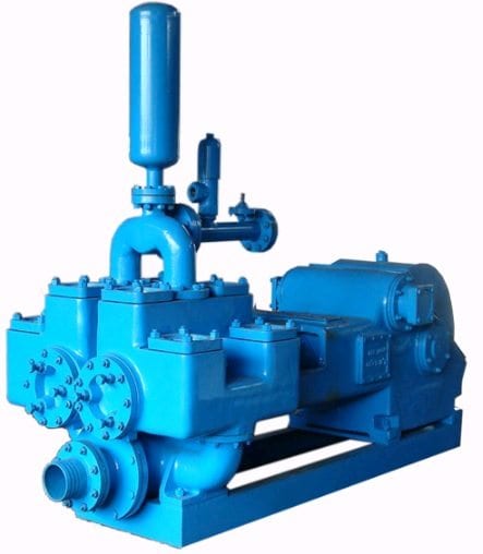
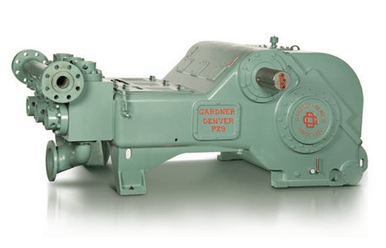
A mud pump is a reciprocating piston/plunger pump designed to circulate drilling fluid under high pressure (up to 7,500 psi (52,000 kPa)) down the drill string and back up the annulus. A duplex mud pump is an important part of the equipment used for oil well drilling.
Duplex mud pumps (two piston/plungers) have generally been replaced by the triplex pump, but are still common in developing countries. Two later developments are the hex pump with six vertical pistons/plungers, and various quintuplex’s with five horizontal piston/plungers. The advantages that Duplex mud pumps have over convention triplex pumps is a lower mud noise which assists with better Measurement while drilling and Logging while drilling decoding.
Use duplex mud pumps to make sure that the circulation of the mud being drilled or the supply of liquid reaches the bottom of the well from the mud cleaning system. Despite being older technology than the triplex mud pump, the duplex mud pumps can use either electricity or diesel, and maintenance is easy due to their binocular floating seals and safety valves.
A mud pump is composed of many parts including mud pump liner, mud pump piston, modules, hydraulic seat pullers, and other parts. Parts of a mud pump:housing itself
Duplex pumps are used to provide a secondary means of fuel transfer in the event of a failure of the primary pump. Each pump in a duplex set is sized to meet the full flow requirements of the system. Pump controllers can be set for any of the following common operating modes:Lead / Lag (Primary / Secondary): The lead (primary) pump is selected by the user and the lag (secondary pump operates when a failure of the primary pump is detected.
Alternating: Operates per Lead / Lag (Primary / Secondary) except that the operating pump and lead / lag status alternate on consecutive starts. A variation is to alternate the pumps based on the operating time (hour meter) of the lead pump.

The design of a slurry pump is critical to making sure that the abrasive and often corrosive aspects of the slurry does not destroy the impeller. Additionally, slurry and sludge may contain large unforeseen solids that will inevitably clog many types of pumps. Since most centrifugal pumps have an impeller with a close tolerance to the volute, the abrasive and sometimes corrosive nature of the slurry will quickly wear the volute and ruin the tolerance. This, in turn, causes the pump to lose its suction capability. This causes massive downtime with slurry pumps along with costly maintenance and spare parts.
For this reason, the EDDY Pump is ideal for slurry pumping applications. The EDDY Pump does not have an impeller, but instead a rotor that does not have any critical tolerances. This allows it to pump slurry at rates of 30% and solids up to 12 inches. This is far more than what centrifugal pumps can handle without any failure or need to change wear parts.

• Barite, ferric oxide, and mineral oil• Base drilling muds• Glass fibers• Sugar processing• Ash or coal conveyers• Cement• Mine de-watering• Lime slurries• Kaolin clay• Crystalline forms

The first step in pump selection is to describe the pump’s requirements. This includes information on the pump design point (head and flow), along with synchronous speeds. After the pump requirements are entered, the program searches and displays a list, showing all pumps meeting your requirements. The selection list can then be sorted by pump size, NPSHr, efficiency and power consumption to simplify your comparison.
A pump curve can be generated showing pump head, efficiency, horsepower and NPSHr as a function of flow rate. An information box displays additional information about the selection. Impeller diameter, speed, shutoff head, maximum horsepower, BEP, minimum flow, motor data and much more information is displayed.
Your selection can be further defined by selecting from a list of more than 120 chemicals to be pumped. Specific gravity, viscosity and temperature can also be specified allowing you to get the most precise pump information available.
Simply click on the pump selection prompt, log in and select all of your pump needs. All selections can be saved, printed or e-mailed. Log on as often as you like.

The positive displacement mud pump is a key component of the drilling process and its lifespan and reliability are critical to a successful operation.
The fluid end is the most easily damaged part of the mud pump. The pumping process occurs within the fluid end with valves, pistons, and liners. Because these components are high-wear items, many pumps are designed to allow quick replacement of these parts.
Due to the nature of its operation, pistons, liners, and valve assemblies will wear and are considered expendable components. There will be some corrosion and metallurgy imperfections, but the majority of pump failures can be traced back to poor maintenance, errors during the repair process, and pumping drilling fluid with excessive solids content.
A few signs include cut piston rubber, discoloration, pistons that are hard to remove, scored liners, valve and seat pitting or cracks, valve inserts severely worn, cracked, or completely missing, and even drilling fluids making their way to the power end of the pump.
The fluid end of a positive displacement triplex pump presents many opportunities for issues. The results of these issues in such a high-pressure system can mean expensive downtime on the pump itself and, possibly, the entire rig — not to mention the costly repair or replacement of the pump. To reduce severe vibration caused by the pumping process, many pumps incorporate both a suction and discharge pulsation dampener; these are connected to the suction and discharge manifolds of the fluid end. These dampeners reduce the cavitation effect on the entire pump which increases the life of everything within the pump.
The fluid end is the most easily damaged part of the mud pump. The pumping process occurs within the fluid end with valves, pistons, and liners. Because these components are high-wear items, many pumps are designed to allow quick replacement of these parts.
Additionally, the throat (inside diameter) can begin to wash out from extended usage hours or rather quickly when the fluid solids content is excessive. When this happens it can cut all the way through the seat and into the fluid end module/seat deck. This causes excessive expense not only from a parts standpoint but also extended downtime for parts delivery and labor hours to remove and replace the fluid module. With that said, a properly operated and maintained mud recycling system is vital to not only the pump but everything the drilling fluid comes in contact with downstream.

Mud recycling systems were once considered optional equipment. Environmental regulations continue to become more stringent and we must all responsibly make a contribution to protect our fragile ecosystem.
Using mud recyclers are a valuable asset to drilling contractors, as well-conditioned drilling fluid can save resources, time and money by reducing the amount of water and chemicals needed by reusing your bentonite and water. This helps maintain borehole stability with consistent mud properties through the entire circulation of the fluid and you haul off mainly the drilled solids, not the entire mud returns, including the liquid.
Drillers considering a mud recycler often ask: “Where do I start?” There are factors to consider before purchasing (or renting) a mud recycler, and, just like sizing the drill rig, sizing the recycler is equally important to your success. The following are some of the questions to ask yourself before making your purchase:
These factors are important to know so that you use a recycler that is sized to clean the mud and protect the components on the rig, pump and cleaner.
As a general rule, size the recycler cleaning capacity to one and a half to two times the pumping volume (max gpm) of the triplex pump. HDD drillers normally run thicker fluids due to the low vertical height and long horizontal lengths of their bores; thicker fluid makes it more difficult for the shakers and cones to process (separate) the solids from the liquids. This is largely due to the natural coating ability of bentonite — It wants to encapsulate the solids and “hold on” to them. By upsizing the recycler, the solid particles have a second or third opportunity to process through the mud recycler for removal before going back to the rig.
Some mud recyclers provide an “onboard” mud pump that was sized specifically to the recycler. This enables the driller to use all available drill rig horsepower toward the rotation and push-pull of the drill pipe, thereby not “robbing” it for an onboard triplex pump.
When choosing a linear shaker for your mud system, look for a long runway (area of length from the front of the shaker to the end where the cuttings dump off). The longer length shaker bed allows extra time for solids to separate from the liquid, and result in drier solids leaving the mud system for disposal. You can also increase the angle of the shaker bed by five degrees to further increase the travel time of the solids.
Proper shaker screen selection enhances the results of the mud recycler, and, combined with the G-Force of the shaker, works in tandem to maximize solids dryness. In the past, shaker screens were sized by mesh size.
Identification of particle sizes from core samples taken on each drilling location provides drillers valuable information and aids in selecting screens. Drilling contractors should carry a couple of testing tools to measure the effectiveness of a of the mud recycler while drilling. These tools are: a Marsh funnel and cup, sand content kit and mud weight scales. Taking mud samples from the return pit or possum belly before the mud is processed, the underflow and overflow of the cones and the clean mud tank help monitor the effectiveness of each component of the recycler, and the driller can make component adjustments to achieve maximum efficiency.
In addition to the shale shakers, another way to size the processing capability of the mud recycler is to look at the hydrocyclone. Depending on the size of the mud recycling system, cone size will be 4, 5, 10 or 12 in. Each size cone has a micron “cut point,” and represents the size of the smallest particle the cone can “pull.” Four- and 5-in. cones have a 20-micron “cut point,” and 10- and 12-in. cones have a 74-micron “cut point.” Smaller mud systems normally have two section tanks, with a ”dirty” tank under the scalping shaker and a “clean” tank under the mud cleaner (shaker with desilting cones), while larger systems can have three section tanks with scalping, desanding and desilting.
Borehole returns require transport into the recycler via a “trash” pump properly sized for the job. Different pumps are available, but the three most common are: 1) submersible, 2) semi-submersible, and 3) aboveground centrifugal with a foot valve. Totally submersible pumps are generally the smallest in size, have a flooded suction to help in priming, and though the most convenient option, are usually the most expensive. Semi-submersible trash pumps still have a flooded suction, but the drive motor is not submerged into the fluid. Semi-submersible pumps work well, but are heavier, and longer than the submersible pumps. Another option is an above ground centrifugal pump with a foot valve, and once primed, is dependable and normally used on larger recyclers for their increased volume capacities.
If your drilling crew has never operated a mud recycler, be sure that you are provided with training and try renting a unit to make sure it is the right “fit” prior to purchase. Be familiar with the maintenance requirements of your mud system; usually the owner’s manual is sufficient, but inquire if the manufacturer offers training videos, onsite or plant training sessions and — the most important — technical support.
In an age where protection of our planet is a major concern, so should your choice of mud systems. Choose a recycler that is respectful to the environment and leaves your jobsite as clean as possible. Do your research, talk to other drillers, decide what you need and you will be able to make the best decision for you and your company.

Knowing the liquid that you are pumping is vital as it allows us to ensure that we offer a pump constructed from compatible materials; thus avoiding potential corrosion and abrasion issues. What is the chemical make up? Are there any solids present, if so what is the maximum particle size and concentration?
The pressure at the inlet and outlet of the pump will determine the type and often the size of pump required. Knowing the pressure you are pumping against allows us to select the most suitable pump technology. If you are unsure of your differential pressure; we can help to calculate it
There are many units of measurement for viscosity however we tend to work in centipoise cP or centistokes cSt. Viscosity is a measure of a liquid’s resistance to deformation caused by stress, or more plainly; the ‘thickness’ of a liquid. Viscosity is typically higher for thicker liquids, for example; water has a viscosity of 1 cp at 20 degC whereas honey has a viscosity of approximately 10000 cp. Viscosity affects the type and size of the pump required, with higher viscosities usually requiring positive displacement units running at lower speeds rather than centrifugal pump solutions.
The density or specific gravity of the pumping liquid at the operating temperature will affect how much power is required to achieve the required duty. This in turn will help us size a suitable drive or motor to operate the pump without a problem.

Many Cat Pumps operate in water conditions more aggressive than the specification above (i.e., reclaim water) yet will provide a satisfactory pump life to the customer because of the care and maintenance support from the customer.
A liquid’s acidic or alkalinity properties defined by its pH number is another consideration when selecting a pump. Cat Pumps recommends the liquid being pumped be within a range of 5 to 9 pH (7 pH is normal water). Liquids rated at a pH of 5 or less will require a seal change and fluid manifold material change (i.e., stainless steel). The same applies to liquids at a pH of 9 or greater. We provide a variety of seal material options to meet a broad range of chemical compatibility requirements.
Temperature is another liquid characteristic that can impact pump performance. The minimum liquid temperature of water that can be pumped with Cat Pumps standard plunger and piston pumps is 34°F (1°C). Below 34°F (1°C) water will begin to freeze and crystallize. Standard pump elastomers are only rated to -22°F (-30°C). Below this temperature, contact Cat Pumps.
Pumping liquid that is lower in temperature than the atmospheric temperature can cause condensation at the back of the plunger and on the plunger rod. If this freezes, it is probable that the ice will damage the oil seals and low-pressure seals as the pump operates.
The maximum liquid temperature of water that can be pumped with Cat Pumps standard plunger and piston pumps from a non-pressurized overhead tank is 130°F (54°C). Pumping higher temperature liquids can increase the risk of cavitation and cause premature wear of the seals. Liquid vapor pressure changes with increased temperature as well.
Special consideration should also be given to handling by-pass liquid. Proper sizing of the holding tank and location of the return by-pass line are critical in accommodating elevated temperatures. In systems with the by-pass routed back to the pump inlet, the installation of a thermal valve is necessary. Contact our technical team for further recommendations on high-temperature systems.
For liquids with more aggressive characteristics, (i.e., hard water, more acidic or basic, elevated temperatures) reduce the pump speed (rpm) of the pump to increase seal life.
A liquid’s thinness or thickness at a given temperature is referred to as its viscosity. Cat Pumps recommends that the viscosity not exceed 500cP (2500 SSU). Viscosity will change with temperature. Typically as a liquid is heated, viscosity decreases. When a liquid is cooled, the viscosity increases.


 8613371530291