
mud pump sheaves free sample

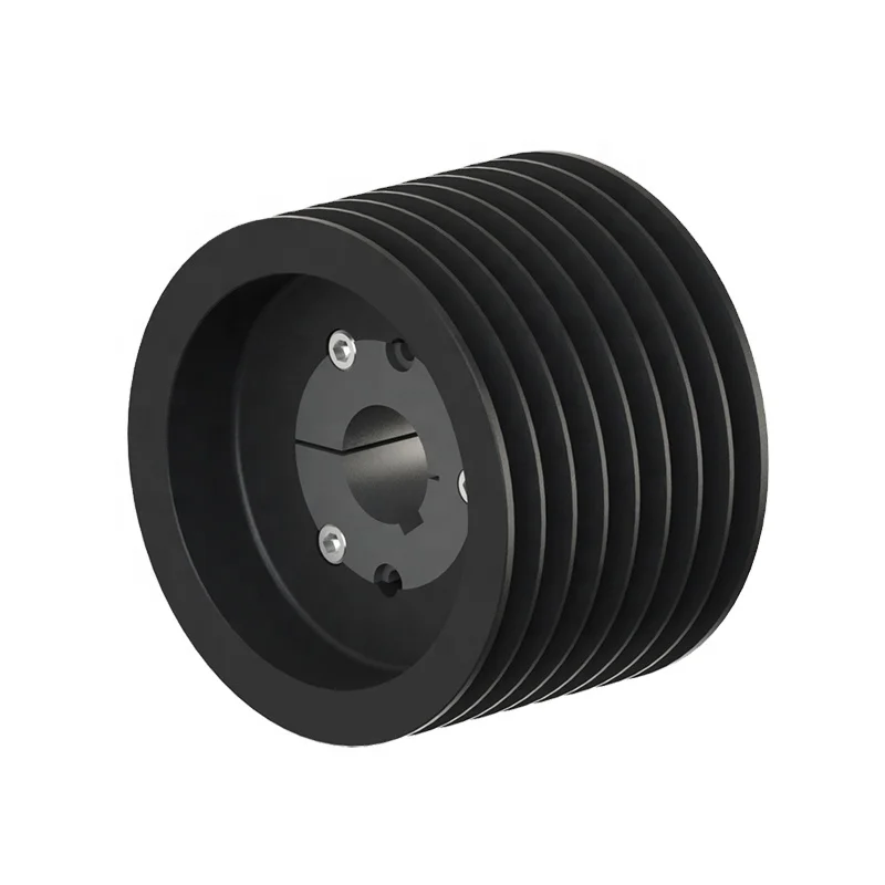
We commonly receive the call to help assist in properly sizing pulleys and sheaves for pump applications. Generally, this is in high pressure wash applications but we also run into a fair amount of agricultural applications where this knowledge can be leveraged. Pulleys or “sheaves” are commonly used for connecting pumps to motors or engines via drive belts. Most pulleys are cast iron or aluminum construction and are offered in either fixed-bore or tapered bushing styles.
For proper operation of any brand or pump type, it is critical to size pulleys and sheaves, correctly, in order to maintain correct RPM, (revolutions per minute). RPM speed is what determines the pump output flow rate – in gallons per minute, liters per minute, etc.
Incorrect pump RPM will adversely affect the pump performance. If the pump is turning too slow – it will not give full performance. Conversely, if the pump is turning too fast, it could cause premature mechanical failures (i.e. valve wear or elastomer failure).
Therefore, it is absolutely critical to ensure correct pulley sizing and analysis of the drive unit, (motor, engine, etc.) relative to the pump. For the sake of this discussion, we will assume standard electric motors at 1750 RPM and standard gas engines at 3400RPM. Do note, one must determine the rpm of their drive unit to be able to accurately calculate the pulley/sheave size.
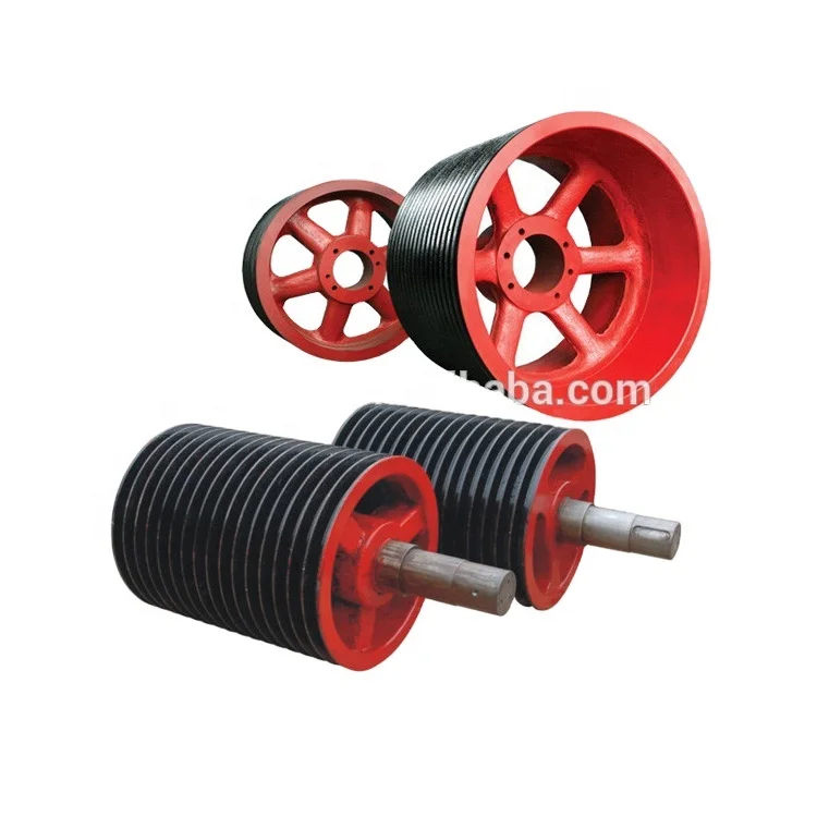
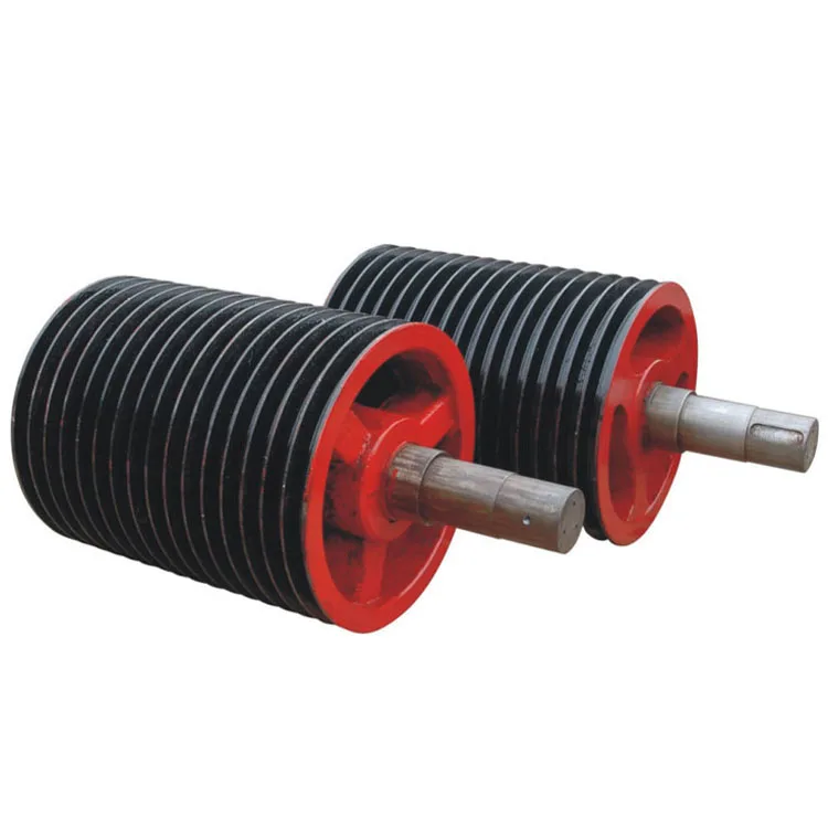
If you start with an incorrect figure for RPM – you will size your equipment incorrectly. This could lead to shorter equipment lifespans and/or reduced output flow rates. Thus, ultimately a less efficient system which equates to more down time and added cost of operation. The scope of this post will be focused towards plunger pump applications. We assemble many units using this method in Omaha, NE. Dultmeier Sales is proud to display the Built in the USA logo on our products. Here are just a handful of the pulley-driven pump products that we offer.
There are complicated formulas for determining pulley ratios but in generic, layman terms, simply divide the driven component (pump) by RPM, the driver component (motor or engine) rated by RPM to get the required ratio. In the example below, the pump RPM is 1070, for full output, while the motor is 1750 RPM.
This means the pulley ratio must be .611 to drive the pump correctly. Hypothetically speaking, if we had a 4 inch pulley on the motor, we would require a 6.55” pulley on the pump. That mathematical equation is as follows: 4” divided by .611 = 6.55”
If the drive pulley on the engine is 4 inches in diameter, we need to calculate 4/.315 = 12.70. This means that the pump pulley must be 12.70 inches, in diameter, to run the pump at 1070 rpm. You can view a technical page from our catalog here – it will help to further explain the calculation process.
Most pulleys, or sheaves, are designed with either fixed shaft bores or tapered bushing hubs. Replaceable hubs fit the required motor or pump shaft size in either inch or mm sizes – depending on the application requirement. These hubs come with bolts to attach them to the pulley, or sheave.
Tapered style hubs simply fit into the pulley opening and then are tightened with two or three set screws, which draw the bushing and pulley together to make one assembly. The pulleys are then attached to the driver (electric motor or gas engine) and driven components (pump). The type of hub, H, SD, SH, etc. must match to a pulley with the same designation for proper fit.
As the information above shows, there are many things involved in order to determine the correct pulleys required to drive your pumps correctly. It is important to remember the larger the difference in pulley sizes, the larger the center distance required to maintain minimum contact with the smaller pulley. We would be glad to help with any sizing for your specific applications. Your Experts in Delivering Fluid Handling Solutions – We Know Flow!
ISO 9001:2000 certified worldwide manufacturer of standard & custom industrial products including sheaves mud pump sheaves. ISO 9001:2000 certified worldwide manufacturer of standard & custom industrial products including V-belt sheaves. V-belt sheaves are available in standard QD style, standard taper bushed style, hi-cap wedge QD style & conventional taper bushed style. Conventional stock sheaves include combination QD sheaves, combination groove TB sheaves, fractional horsepower sheaves, single groove variable pitch sheaves & two groove variable pitch sheaves. Hi-cap wedge QD style feature 2 groves & 3V belt cross sections. Hi-cap wedge QD style out side dia. sizes ranging from 220 in. to 2.2 in.

F04B15/02—Pumps adapted to handle specific fluids, e.g. by selection of specific materials for pumps or pump parts the fluids being viscous or non-homogeneous
A quintuplex mud pump has a crankshaft supported in the pump by external main bearings. The crankshaft has five eccentric sheaves, two internal main bearing sheaves, and two bull gears. Each of the main bearing sheaves supports the crankshaft by a main bearing. One main bearing sheave is disposed between second and third eccentric sheaves, while the other main bearing sheave is disposed between third and fourth eccentric sheaves. One bull gear is disposed between the first and second eccentric sheaves, while the second bull gear is disposed between fourth and fifth eccentric sheaves. A pinion shaft has pinion gears interfacing with the crankshaft"s bull gears. Connecting rods on the eccentric sheaves use roller bearings and transfer rotational movement of the crankshaft to pistons of the pump"s fluid assembly.
Triplex mud pumps pump drilling mud during well operations. An example of a typical triplex mud pump 10 shown in FIG. 1A has a power assembly 12, a crosshead assembly 14, and a fluid assembly 16. Electric motors (not shown) connect to a pinion shaft 30 that drives the power assembly 12. The crosshead assembly 14 converts the rotational movement of the power assembly 12 into reciprocating movement to actuate internal pistons or plungers of the fluid assembly 16. Being triplex, the pump"s fluid assembly 16 has three internal pistons to pump the mud.
As shown in FIG. 1B, the pump"s power assembly 14 has a crankshaft 20 supported at its ends by double roller bearings 22. Positioned along its intermediate extent, the crankshaft 20 has three eccentric sheaves 24-1 . . . 24-3, and three connecting rods 40 mount onto these sheaves 24 with cylindrical roller bearings 26. These connecting rods 40 connect by extension rods (not shown) and the crosshead assembly (14) to the pistons of the pump"s fluid assembly 16.
In addition to the sheaves, the crankshaft 20 also has a bull gear 28 positioned between the second and third sheaves 24-2 and 24-3. The bull gear 28 interfaces with the pinion shaft (30) and drives the crankshaft 20"s rotation. As shown particularly in FIG. 1C, the pinion shaft 30 also mounts in the power assembly 14 with roller bearings 32 supporting its ends. When electric motors couple to the pinion shaft"s ends 34 and rotate the pinion shaft 30, a pinion gear 38 interfacing with the crankshaft"s bull gear 28 drives the crankshaft (20), thereby operating the pistons of the pump"s fluid assembly 16.
When used to pump mud, the triplex mud pump 10 produces flow that varies by approximately 23%. For example, the pump 10 produces a maximum flow level of about 106% during certain crankshaft angles and produces a minimum flow level of 83% during other crankshaft angles, resulting in a total flow variation of 23% as the pump"s pistons are moved in differing exhaust strokes during the crankshaft"s rotation. Because the total flow varies, the pump 10 tends to produce undesirable pressure changes or “noise” in the pumped mud. In turn, this noise interferes with downhole telemetry and other techniques used during measurement-while-drilling (MWD) and logging-while-drilling (LWD) operations.
In contrast to mud pumps, well-service pumps (WSP) are also used during well operations. A well service pump is used to pump fluid at higher pressures than those used to pump mud. Therefore, the well service pumps are typically used to pump high pressure fluid into a well during frac operations or the like. An example of a well-service pump 50 is shown in FIG. 2. Here, the well service pump 50 is a quintuplex well service pump, although triplex well service pumps are also used. The pump 50 has a power assembly 52, a crosshead assembly 54, and a fluid assembly 56. A gear reducer 53 on one side of the pump 50 connects a drive (not shown) to the power assembly 52 to drive the pump 50.
As shown in FIG. 3, the pump"s power assembly 52 has a crankshaft 60 with five crankpins 62 and an internal main bearing sheave 64. The crankpins 62 are offset from the crankshaft 60"s axis of rotation and convert the rotation of the crankshaft 60 in to a reciprocating motion for operating pistons (not shown) in the pump"s fluid assembly 56. Double roller bearings 66 support the crankshaft 60 at both ends of the power assembly 52, and an internal double roller bearing 68 supports the crankshaft 60 at its main bearing sheave 64. One end 61 of the crankshaft 60 extends outside the power assembly 52 for coupling to the gear reducer (53; FIG. 2) and other drive components.
As shown in FIG. 4A, connecting rods 70 connect from the crankpins 62 to pistons or plungers 80 via the crosshead assembly 54. FIG. 4B shows a typical connection of a connecting rod 70 to a crankpin 62 in the well service pump 50. As shown, a bearing cap 74 fits on one side of the crankpin 62 and couples to the profiled end of the connecting rod 70. To reduce friction, the connection uses a sleeve bearing 76 between the rod 70, bearing cap 74, and crankpin 62. From the crankpin 62, the connecting rod 70 connects to a crosshead 55 using a wrist pin 72 as shown in FIG. 4A. The wrist pin 72 allows the connecting rod 70 to pivot with respect to the crosshead 55, which in turn is connected to the plunger 80.
In use, an electric motor or an internal combustion engine (such as a diesel engine) drives the pump 50 by the gear reducer 53. As the crankshaft 60 turns, the crankpins 62 reciprocate the connecting rods 70. Moved by the rods 70, the crossheads 55 reciprocate inside fixed cylinders. In turn, the plunger 80 coupled to the crosshead 55 also reciprocates between suction and power strokes in the fluid assembly 56. Withdrawal of a plunger 80 during a suction stroke pulls fluid into the assembly 56 through the input valve 82 connected to an inlet hose or pipe (not shown). Subsequently pushed during the power stroke, the plunger 80 then forces the fluid under pressure out through the output valve 84 connected to an outlet hose or pipe (not shown).
In contrast to using a crankshaft for a quintuplex well-service pump that has crankpins 62 as discussed above, another type of quintuplex well-service pump uses eccentric sheaves on a direct drive crankshaft. FIG. 4C is an isolated view of such a crankshaft 90 having eccentric sheaves 92-1 . . . 92-5 for use in a quintuplex well-service pump. External main bearings (not shown) support the crankshaft 90 at its ends 96 in the well-service pumps housing (not shown). To drive the crankshaft 90, one end 91 extends beyond the pumps housing for coupling to drive components, such as a gear box. The crankshaft 90 has five eccentric sheaves 92-1 . . . 92-5 for coupling to connecting rods (not shown) with roller bearings. The crankshaft 90 also has two internal main bearing sheaves 94-1, 94-2 for internal main bearings used to support the crankshaft 90 in the pump"s housing.
In the past, quintuplex well-service pumps used for pumping frac fluid or the like have been substituted for mud pumps during drilling operations to pump mud. Unfortunately, the well-service pump has a shorter service life compared to the conventional triplex mud pumps, making use of the well-service pump as a mud pump less desirable in most situations. In addition, a quintuplex well-service pump produces a great deal of white noise that interferes with MWD and LWD operations, further making the pump"s use to pump mud less desirable in most situations. Furthermore, the well-service pump is configured for direct drive by a motor and gear box directly coupling on one end of the crankshaft. This direct coupling limits what drives can be used with the pump. Moreover, the direct drive to the crankshaft can produce various issues with noise, balance, wear, and other associated problems that make use of the well-service pump to pump mud less desirable.
One might expect to provide a quintuplex mud pump by extending the conventional arrangement of a triplex mud pump (e.g., as shown in FIG. 1B) to include components for two additional pistons or plungers. However, the actual design for a quintuplex mud pump is not as easy as extending the conventional arrangement, especially in light of the requirements for a mud pump"s operation such as service life, noise levels, crankshaft deflection, balance, and other considerations. As a result, acceptable implementation of a quintuplex mud pump has not been achieved in the art during the long history of mud pump design.
What is needed is an efficient mud pump that has a long service life and that produces low levels of white noise during operation so as not to interfere with MWD and LWD operations while pumping mud in a well.
A quintuplex mud pump is a continuous duty, reciprocating plunger/piston pump. The mud pump has a crankshaft supported in the pump by external main bearings and uses internal gearing and a pinion shaft to drive the crankshaft. Five eccentric sheaves and two internal main bearing sheaves are provided on the crankshaft. Each of the main bearing sheaves supports the intermediate extent of crankshaft using bearings. One main bearing sheave is disposed between the second and third eccentric sheaves, while the other main bearing sheave is disposed between the third and fourth eccentric sheaves.
One or more bull gears are also provided on the crankshaft, and the pump"s pinion shaft has one or more pinion gears that interface with the one or more bull gears. If one bull gear is used, the interface between the bull and pinion gears can use herringbone or double helical gearing of opposite hand to avoid axial thrust. If two bull gears are used, the interface between the bull and pinion gears can use helical gearing with each having opposite hand to avoid axial thrust. For example, one of two bull gears can be disposed between the first and second eccentric sheaves, while the second bull gear can be disposed between fourth and fifth eccentric sheaves. These bull gears can have opposite hand. The pump"s internal gearing allows the pump to be driven conventionally and packaged in any standard mud pump packaging arrangement. Electric motors (for example, twin motors made by GE) may be used to drive the pump, although the pump"s rated input horsepower may be a factor used to determine the type of motor.
Connecting rods connect to the eccentric sheaves and use roller bearings. During rotation of the crankshaft, these connecting rods transfer the crankshaft"s rotational movement to reciprocating motion of the pistons or plungers in the pump"s fluid assembly. As such, the quintuplex mud pump uses all roller bearings to support its crankshaft and to transfer crankshaft motion to the connecting rods. In this way, the quintuplex mud pump can reduce the white noise typically produced by conventional triplex mud pumps and well service pumps that can interfere with MWD and LWD operations.
Turning to the drawings, a quintuplex mud pump 100 shown in FIGS. 5 and 6A-6B has a power assembly 110, a crosshead assembly 150, and a fluid assembly 170. Twin drives (e.g., electric motors, etc.) couple to ends of the power assembly"s pinion shaft 130 to drive the pump"s power assembly 110. As shown in FIGS. 6A-6B, internal gearing within the power assembly 110 converts the rotation of the pinion shaft 130 to rotation of a crankshaft 120. The gearing uses pinion gears 138 on the pinion shaft 130 that couple to bull gears 128 on the crankshaft 120 and transfer rotation of the pinion shaft 130 to the crankshaft 120.
For support, the crankshaft 120 has external main bearings 122 supporting its ends and two internal main bearings 127 supporting its intermediate extent in the assembly 110. As best shown in FIG. 6A, rotation of the crankshaft 120 reciprocates five independent connecting rods 140. Each of the connecting rods 140 couples to a crosshead 160 of the crosshead assembly 150. In turn, each of the crossheads 160 converts the connecting rod 40"s movement into a reciprocating movement of an intermediate pony rod 166. As it reciprocates, the pony rod 166 drives a coupled piston or plunger (not shown) in the fluid assembly 170 that pumps mud from an intake manifold 192 to an output manifold 198. Being quintuplex, the mud pump 100 has five such pistons movable in the fluid assembly 170 for pumping the mud.
Shown in isolated detail in FIG. 7, the crankshaft 120 has five eccentric sheaves 124-1 through 124-5 disposed thereon. Each of these sheaves can mechanically assemble onto the main vertical extent of the crankshaft 120 as opposed to being welded thereon. During rotation of the crankshaft 120, the eccentric sheaves actuate in a firing order of 124-1, 3, 5, 2 and 4 to operate the fluid assembly"s pistons (not shown). This order allows the crankshaft 120 to be assembled by permitting the various sheaves to be mounted thereon. Preferably, each of the eccentric sheaves 124-1 . . . 124-5 is equidistantly spaced on the crankshaft 120 for balance.
The crankshaft 120 also has two internal main bearing sheaves 125-1 and 125-2 positioned respectively between the second and third sheaves 124-2 and 124-3 and the third and fourth sheaves 124-3 and 124-4. In the present embodiment, the crankshaft 120 also has two bull gear supports 128-1 and 128-2 disposed thereon, although one bull gear may be used by itself in other embodiments. The first bull gear support 128-1 is positioned between the first and second eccentric sheaves 124-1 and 124-2, and the second of the bull gear support 128-2 is positioned between the fourth and fifth eccentric sheaves 124-4 and 124-5.
Preferably, each of the sheaves 124-1 . . . 124-5, bull gear supports 128-1 & 128-2, and bearing sheaves 125-1 & 125-2 are equidistantly spaced on the crankshaft 120 for balance. In one implementation for the crankshaft 120 having a length a little greater than 90-in. (e.g., 90.750-in.), each of the sheaves 124, 125 and supports 128 are equidistantly spaced from one another by 9-inches between their rotational centers. The end sheaves 124-1 and 124-5 can be positioned a little over 9-in. (e.g., 9.375-in.) from the ends of the crankshaft 120.
The additional detail of FIG. 8 shows the crankshaft 120 supported in the power assembly 110 and having the connecting rods 140 mounted thereon. As noted above, double roller bearings 122 support the ends of the crankshaft 120 in the assembly 110. Internally, main bearings 123 support the intermediate extent of the crankshaft 120 in the assembly 110. In particular, the main bearings 126 position on the main bearing sheaves 125-1 and 125-2 and are supported by carriers 125 mounted to the assembly 110 at 129. The external main bearings 122 are preferably spherical bearings to better support radial and axial loads. The internal main bearings 125 preferably use cylindrical bearings.
Five connector rods 140 use roller bearings 126 to fit on the eccentric sheaves 124-1 . . . 124-5. Each of the roller bearings 126 preferably uses cylindrical bearings. The rods 140 extend from the sheaves 124-1 . . . 124-5 (perpendicular to the figure) and couple the motion of the crankshaft 120 to the fluid assembly (170) via crossheads (160) as is discussed in more detail below with reference to FIGS. 10A-10B.
The cross-section in FIG. 10A shows a crosshead 160 for the quintuplex mud pump. The end of the connecting rod 140 couples by a wrist pin 142 and bearing 144 to a crosshead body 162 that is movable in a crosshead guide 164. A pony rod 166 coupled to the crosshead body 162 extends through a stuffing box gasket 168 on a diaphragm plate 169. An end of this pony rod 166 in turn couples to additional components of the fluid assembly (170) as discussed below.
The cross-section in FIG. 10B shows portion of the fluid assembly 170 for the quintuplex mud pump. An intermediate rod 172 has a clamp 174 that couples to the pony rod (166; FIG. 10A) from the crosshead assembly 160 of FIG. 10A. The opposite end of the rod 172 couples by another clamp to a piston rod 180 having a piston head 182 on its end. Although a piston arrangement is shown, the fluid assembly 170 can use a plunger or any other equivalent arrangement so that the terms piston and plunger can be used interchangeably herein. Moved by the pony rod (166), the piston head 182 moves in a liner 184 communicating with a fluid passage 190. As the piston 182 moves, it pulls mud from a suction manifold 192 through a suction valve 194 into the passage 190 and pushes the mud in the passage 190 to a discharge manifold 198 through a discharge valve 196.
As noted previously, a triplex mud pump produces a total flow variation of about 23%. Because the present mud pump 100 is quintuplex, the pump 100 offers a lower variation in total flow, making the pump 100 better suited for pumping mud and producing less noise that can interfere with MWD and LWD operations. In particular, the quintuplex mud pump 100 can produce a total flow variation as low as about 7%. For example, the quintuplex mud pump 100 can produce a maximum flow level of about 102% during certain crankshaft angles and can produce a minimum flow level of 95% during other crankshaft angles as the pump"s five pistons move in their differing strokes during the crankshaft"s rotation. Being smoother and closer to ideal, the lower total flow variation of 7% produces less pressure changes or “noise” in the pumped mud that can interfere with MWD and LWD operations.
Although a quintuplex mud pump is described above, it will be appreciated that the teachings of the present disclosure can be applied to multiplex mud pumps having at least more than three eccentric sheaves, connecting rods, and fluid assembly pistons. Preferably, the arrangement involves an odd number of these components so such mud pumps may be septuplex, nonuplex, etc. For example, a septuplex mud pump according to the present disclosure may have seven eccentric sheaves, connecting rods, and fluid assembly pistons with at least two bull gears and at least two bearing sheaves on the crankshaft. The bull gears can be arranged between first and second eccentric sheaves and sixth and seventh eccentric sheaves on the crankshaft. The internal main bearings supporting the crankshaft can be positioned between third and fourth eccentric sheaves and the fourth and fifth eccentric sheaves on the crankshaft.
a crankshaft rotatably supported in the pump by a plurality of main bearings, the crankshaft having five eccentric sheaves and a first bull gear disposed thereon, the main bearings including a first internal main bearing sheave disposed between the second and third eccentric sheaves and including a second internal main bearing sheave disposed between the third and fourth eccentric sheaves;
a pinion shaft for driving the crankshaft, the pinion shaft rotatably supported in the pump and having a first pinion gear interfacing with the first bull gear on the crankshaft; and
6. A pump of claim 1, wherein the crankshaft comprises a second bull gear disposed thereon, and wherein the pinion shaft comprises a second pinion gear disposed thereon and interfacing with the second bull gear.
7. A pump of claim 6, wherein the first bull gear is disposed between the first and second eccentric sheaves, and wherein the second bull gear is disposed between the fourth and fifth eccentric sheaves.
8. A pump of claim 6, wherein the five eccentric sheaves, the first and second internal main bearing sheaves, and the first and second bull gears are equidistantly spaced from one another on the crankshaft.
9. A pump of claim 6, wherein the first and second pinion gears comprise helical gearing of opposite hand, and wherein the first and second bull gears comprise helical gearing of opposite hand complementary to the pinion gears.
a crankshaft rotatably supported in the pump by two external main bearings and two internal main bearings, the crankshaft having five eccentric sheaves, two internal main bearing sheaves for the internal main bearings, and at least one bull gear disposed thereon;
13. A pump of claim 11, wherein a first of the main bearing sheaves is disposed between the second and third eccentric sheaves, and wherein a second of the main bearing sheaves is disposed between the third and fourth eccentric sheaves.
16. A pump of claim 11, wherein the at least one bull gear comprises first and second bull gears disposed on the crankshaft, and wherein the at least one pinion gear comprises first and second pinion gears disposed on the crankshaft.
17. A pump of claim 16, wherein the first bull gear is disposed between the first and second eccentric sheaves, and wherein the second bull gear is disposed between the fourth and fifth eccentric sheaves.
18. A pump of claim 16, wherein the five eccentric sheaves, the two internal main bearing sheaves, and the first and second bull gears are equidistantly spaced from one another on the crankshaft.
19. A pump of claim 16, wherein the first and second pinion gears comprise helical gearing of opposite hand, and wherein the first and second bull gears comprise helical gearing of opposite hand complementary to the pinion gears.
a crankshaft rotatably supported in the pump by a plurality of main bearings, the crankshaft having five eccentric sheaves and first and second bull gears disposed thereon, the first bull gear disposed between the first and second eccentric sheaves, the second bull gear disposed between the fourth and fifth eccentric sheaves;
a pinion shaft for driving the crankshaft, the pinion shaft rotatably supported in the pump, the pinion shaft having a first pinion gear interfacing with the first bull gear on the crankshaft and having a second pinion gear interfacing with the second bull gear on the crankshaft; and
26. A pump of claim 21, wherein the main bearings include first and second internal main gearing sheaves disposed on the crankshaft, and wherein the five eccentric sheaves, the two internal main bearing sheaves, and the first and second bull gears are equidistantly spaced from one another on the crankshaft.
27. A pump of claim 21, wherein the first and second pinion gears comprise helical gearing of opposite hand, and wherein the first and second bull gears comprise helical gearing of opposite hand complementary to the pinion gears.
a crankshaft rotatably supported in the pump by a plurality of main bearings, the crankshaft having five eccentric sheaves and first and second bull gears disposed thereon, the main bearings including two internal main bearing sheaves disposed on the crankshaft, wherein the five eccentric sheaves, the two internal main bearing sheaves, and the first and second bull gears are equidistantly spaced from one another on the crankshaft;
a pinion shaft for driving the crankshaft, the pinion shaft rotatably supported in the pump, the pinion shaft having a first pinion gear interfacing with the first bull gear on the crankshaft and having a second pinion gear interfacing with the second bull gear on the crankshaft; and
34. A pump of claim 29, wherein the first and second pinion gears comprise helical gearing of opposite hand, and wherein the first and second bull gears comprise helical gearing of opposite hand complementary to the pinion gears.
"Triplex Mud Pump Parts and Accessories;" Product Information Brochure; copyright 2007 Sunnda LLC; downloaded from http://www.triplexmudpump.com/triplex-mud-pump-parts.php on Sep. 5, 2008.
"Triplex Mud Pumps Triplex Mud Pump Parts for Sale;" copyright 2007 Sunnda LLC; Product Information Brochure located at http://www.triplexmudpump.com/.
"Triplex Mud Pumps Triplex Mud Pump Parts;" copyright 2007 Sunnda LLC; downloaded from http://www.triplexmudpump.com/F-series-triplex-mud-pumps-power-end.php on Sep. 5, 2008.
China Petrochemical International Co., Ltd.; "Quintuplex Mud Pump;" Product Information Brochure downloaded from http://www.intl.sinopec.com.cn/emExp/upstream/Quituplex-Mud-Pump.htm downloaded on Oct. 2, 2008.
FMC Technologies; "Fluid Control: Well Service Pump;" Product Information Brochure; downloaded from http://www.fmctechnologies.com/-FluidControl-old/WellServicePump.aspx on Sep. 5, 2008.
National Oilwell; "Triplex Mud Pumps;" Product Information Brochure; downloaded from http://nql.com/Archives/2000%20Composite%20Catalog/pg-32.html downloaded on Sep. 5, 2008.
NOV 12-P-160 Mud Pump is rated at 1600 input horsepower (1193 kw) at 120 strokes per minute, with a 12-inch (304.8 mm) stroke. Multiple liner sizes allow pressures and volumes to handle circulation requirements in deep drilling applications.
Flexibility: Compact engineering provides higher efficiency in less space. The NOV 12-P-160 Triplex Mud Pump light weight and flexible design make it easily adaptable to a variety of rig configurations. This provides flexibility as drilling requirements and conditions change.
Fluid End Modules: NOV offers a choice of fluid end modules and valve covers for every P Series pump model to select the fluid end module that exactly matches drilling requirements. All pump models can be equipped with either the standard or premium forged, two-piece interchangeable fluid modules
The flexibility of Wood’s engineering, foundry and machine shop facilities allows us to design and manufacture special non-standard (made-to-order) sheaves and pulleys to meet a variety of customer requirements.

For high-power requirements, two or more V-belts can be joined side-by-side in an arrangement called a multi-V, running on matching multi-groove sheaves. This is known as a
most common applications are low HP diesel engines, processing machines, pumps, mining, compressors saw and milling. They have a good temperature resistance (-31°F to 158°F)
The belt is placed around the two sheaves while the center distance between them is reduced, Then the sheaves are moved apart. Moving the sheaves apart produces
Belts and sheaves simply "wear out" and need to be replaced after a while. But how do we know when? Well, here"s a drawing that will give you an idea of
"3V", etc.) the belt will sit with its outside diameter pretty close to the outside circumference of the sheave. That"s when you know you"ve got it right. Some sheaves,
different sizes/types of sheaves. And this is only a sampling... "2L, 3L, 4L, 5L; A, B, C, D, E; 3V, 5V, 8V; and metric... SPZ, SPA, SPB, SPC". Now that"s a lot of belts.

Pitch Diameter (Motor Pulley) =Pump RPM X Pitch Diameter of Pump Pulley Motor RPM
Pitch Diameter (Pump Pulley) =Motor RPM X Pitch Diameter of Motor Pulley Pump RPM

For 50 years, Giant Pumps has offered the most dependable positive displacement high-pressure triplex pumps available. Designed and built to the highest quality standards, customers count on Giant Pumps products to keep their equipment running. Every design detail of Giant Pumps products is optimized for long-life and reliable performance, making Giant Pumps the most trusted name in high-pressure pumps and systems.

n: a pump with an impeller or rotor, an impeller shaft, and a casing, which discharges fluid by centrifugal force. An electric submersible pump is a centrifugal pump.
n: a method of improved oil recovery in which chemicals dissolved in water are pumped into a reservoir through injection wells to mobilize oil left behind after primary or secondary recovery and to move it toward production wells.
n: a device with an orifice installed in a line to restrict the flow of fluids. Surface chokes are part of the Christmas tree on a well and contain a choke nipple, or bean, with a small-diameter bore that serves to restrict the flow. Chokes are also used to control the rate of flow of the drilling mud out of the hole when the well is closed in with the blowout preventer and a kick is being circulated out of the hole. See choke manifold.
n: the movement of drilling fluid out of the mud pits, down the drill stem, up the annulus, and back to the mud pits. See normal circulation, reverse circulation.
n: the equipment for transporting and using coiled tubing, including a reel for the coiled tubing, an injector head to push the tubing down the well, a wellhead blowout preventer stack, a power source (usually a diesel engine and hydraulic pumps), and a control console. A unique feature of the unit is that it allows continuous circulation while it is being lowered into the hole. A coiled tubing unit is usually mounted on a trailer or skid.
n: low-solids fluid or drilling mud used when a well is being completed. It is selected not only for its ability to control formation pressure, but also for the properties that minimize formation damage.
n: 1. a mechanism used to transmit power from the engines to the pump, the drawworks, and other machinery on a drilling rig. It is composed of clutches, chains and sprockets, belts and pulleys, and a number of shafts, both driven and driving. v: to connect two or more power producing devices, such as engines, to run driven equipment, such as the drawworks.
n: generally, the first string of casing in a well. It may be lowered into a hole drilled into the formations near the surface and cemented in place; it may be driven into the ground by a special pile driver (in such cases, it is sometimes called drive pipe). Its purpose is to prevent the soft formations near the surface from caving in and to conduct drilling mud from the bottom of the hole to the surface when drilling starts. Also called conductor pipe, drive pipe.
n: a weight applied to compensate for existing weight or force. On pumping units in oil production, counterweights are used to offset the weight of the column of sucker rods and fluid on the upstroke of the pump, and the weight of the rods on the downstroke.
n: an arm keyed at right angles to a shaft and used for changing radius of rotation or changing reciprocating motion to circular motion or circular motion to reciprocating motion. On a beam pumping unit, the crank is connected by the pitman to the walking beam, thereby changing circular motion to reciprocating motion.
n pl: the fragments of rock dislodged by the bit and brought to the surface in the drilling mud. Washed and dried cuttings samples are analyzed by geologists to obtain information about the formations drilled.


 8613371530291