
mud pump sheaves made in china

Find W series mud pump from pressure grouting pump manufacturer - Saigao gruop in China. The W series mud pump can be widely used in all kinds of works in oil field, which is su...

A wide variety of mud pump pulley options are available to you, such as 1 year, not available and 2 years.You can also choose from new, mud pump pulley,As well as from energy & mining, construction works , and machinery repair shops. And whether mud pump pulley is 1.5 years, unavailable, or {3}.

A wide variety of belt pulley hydraulic pump options are available to you, You can also choose from gear pump, belt pulley hydraulic pump,As well as from 1 year, 6 months, and 3 months. and whether belt pulley hydraulic pump is indonesia, spain, or russia.

Triplex: This mud pump is used for drilling applications needing high pump pressure. This model works by decreasing the working fluid volume being discharged to generate pressure for producing the flow. There are three pistons in the triplex pump, with the middle piston generating more pressure on the crankshaft. High piston load can lead to excessive pressure and crankshaft failure if the components are not properly sourced.
Quintuplex:Quintuplex mud pump is perfect for pumping fluid at the time of drilling operations. It works as a continuous duty return piston. This is used in terms of its external bearings to provide crankshaft support to ensure the proper functioning of the sheaves.
Duplex: These mud pumps ensure that the mud circulation reaches the well"s bottom from the mud cleaning system. Duplex pumps have binocular floating seals as well as safety valves.
Saigao offers high-quality OEM mud pump spares, consumables, expendables and spare parts. Our mud pump parts are made with the highest standards of quality, offering competitive pricing and exceptional durability.

ISO 9001:2000 certified worldwide manufacturer of standard & custom industrial products including sheaves mud pump sheaves. ISO 9001:2000 certified worldwide manufacturer of standard & custom industrial products including V-belt sheaves. V-belt sheaves are available in standard QD style, standard taper bushed style, hi-cap wedge QD style & conventional taper bushed style. Conventional stock sheaves include combination QD sheaves, combination groove TB sheaves, fractional horsepower sheaves, single groove variable pitch sheaves & two groove variable pitch sheaves. Hi-cap wedge QD style feature 2 groves & 3V belt cross sections. Hi-cap wedge QD style out side dia. sizes ranging from 220 in. to 2.2 in.

The Hook Block includes a traveling block and a hook, it can be used to lifting drill string when in drilling situation. Its housing assembly is made of thick section steel plate and wire rope is kept taut when hoisting or lowering the unload block. Sheave grooves are hardened by medium frequency induction to provided extended service life Working sheaves have double-row conical roller bearings and each bearing is individually lubricated The sheaves are interchangeable with Corresponding Crown Block.The Traveling Block and the Hook conforms to 8C.
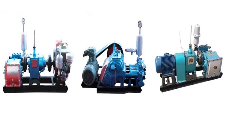
Mud Pumps are available for the different purposes of drilling and extracting of oil. In fact, the Unitized Pumps are a work of the hydraulic mechanical transmission. Unitized pump parts include 4 types of packages such as the air clutch transmission takes in the diesel engine, transmission (including card and shaft, decelerator, clutch, belt and pulley) and the Mud pump. The Mud Pumps are also inclusive of the hydraulic coupling transmission that consists of the diesel engine, hydraulic coupling and the Mud pump. It also includes the electric drive Mud pump and the chain transmission for apt design and assembling.
The Unitized design Pumps are built as well as licensed according to the specifications of the American Petroleum Institute where the master skid is the standard oilfield 3 runner skid. Mud Pumps like the F 1000 are driven by the diesel engine with the help of the narrow V belts. Pumps are complete with a bulk wheel, a set of V belts, a screw assembly, a belt guard and the screw devices for tightening the belts. Mud pump like the triplex liner single action pumps has an input power of 1000 horse power. The maximum stroke is all of 10 inches or 254 mm.
Mud parts also contain a maximum working pressure of 5000 PSI or 35 MPA. The Mud Pumps have a gear type made of integral herring bone with API 6 valve pots. The intake of the F 1000 Pumps is 12 inches or 305 mm and they have a discharge space of 4 inches or 102 mm. Mud pump also contain a pulsation dampener model that has a capacity of 75.7 liters or 20 gallons. The relief valve and pressure gauge are also an important part of the Mud pump as they help in various ways.
Mud pump like the diesel engine has a rated speed of about 1200 revolutions per minute and the movement takes place in an anticlockwise direction with the face output shaft end. For the purpose of testing and commissioning, the Mud pump needs to be installed and secured with machinery and different kinds of equipment. Furnish the lube products for testing and the diesel is required to be run for testing the transmission devices. To give you an idea, the Mud pump that is being discussed in this category is available at competitive prices and can be obtained for pneumatic clutch transmission that can be adjusted according to customer’s requirements.

Triplex mud pumps pump drilling mud during well operations. An example of a typical triplex mud pump 10 shown in FIG. 1A has a power assembly 12, a crosshead assembly 14, and a fluid assembly 16. Electric motors (not shown) connect to a pinion shaft 30 that drives the power assembly 12. The crosshead assembly 14 converts the rotational movement of the power assembly 12 into reciprocating movement to actuate internal pistons or plungers of the fluid assembly 16. Being triplex, the pump"s fluid assembly 16 has three internal pistons to pump the mud.
As shown in FIG. 1B, the pump"s power assembly 14 has a crankshaft 20 supported at its ends by double roller bearings 22. Positioned along its intermediate extent, the crankshaft 20 has three eccentric sheaves 24-1 . . . 24-3, and three connecting rods 40 mount onto these sheaves 24 with cylindrical roller bearings 26. These connecting rods 40 connect by extension rods (not shown) and the crosshead assembly (14) to the pistons of the pump"s fluid assembly 16.
In addition to the sheaves, the crankshaft 20 also has a bull gear 28 positioned between the second and third sheaves 24-2 and 24-3. The bull gear 28 interfaces with the pinion shaft (30) and drives the crankshaft 20"s rotation. As shown particularly in FIG. 1C, the pinion shaft 30 also mounts in the power assembly 14 with roller bearings 32 supporting its ends. When electric motors couple to the pinion shaft"s ends 34 and rotate the pinion shaft 30, a pinion gear 38 interfacing with the crankshaft"s bull gear 28 drives the crankshaft (20), thereby operating the pistons of the pump"s fluid assembly 16.
When used to pump mud, the triplex mud pump 10 produces flow that varies by approximately 23%. For example, the pump 10 produces a maximum flow level of about 106% during certain crankshaft angles and produces a minimum flow level of 83% during other crankshaft angles, resulting in a total flow variation of 23% as the pump"s pistons are moved in differing exhaust strokes during the crankshaft"s rotation. Because the total flow varies, the pump 10 tends to produce undesirable pressure changes or “noise” in the pumped mud. In turn, this noise interferes with downhole telemetry and other techniques used during measurement-while-drilling (MWD) and logging-while-drilling (LWD) operations.
In contrast to mud pumps, well-service pumps (WSP) are also used during well operations. A well service pump is used to pump fluid at higher pressures than those used to pump mud. Therefore, the well service pumps are typically used to pump high pressure fluid into a well during frac operations or the like. An example of a well-service pump 50 is shown in FIG. 2. Here, the well service pump 50 is a quintuplex well service pump, although triplex well service pumps are also used. The pump 50 has a power assembly 52, a crosshead assembly 54, and a fluid assembly 56. A gear reducer 53 on one side of the pump 50 connects a drive (not shown) to the power assembly 52 to drive the pump 50.
As shown in FIG. 3, the pump"s power assembly 52 has a crankshaft 60 with five crankpins 62 and an internal main bearing sheave 64. The crankpins 62 are offset from the crankshaft 60"s axis of rotation and convert the rotation of the crankshaft 60 in to a reciprocating motion for operating pistons (not shown) in the pump"s fluid assembly 56. Double roller bearings 66 support the crankshaft 60 at both ends of the power assembly 52, and an internal double roller bearing 68 supports the crankshaft 60 at its main bearing sheave 64. One end 61 of the crankshaft 60 extends outside the power assembly 52 for coupling to the gear reducer (53; FIG. 2) and other drive components.
As shown in FIG. 4A, connecting rods 70 connect from the crankpins 62 to pistons or plungers 80 via the crosshead assembly 54. FIG. 4B shows a typical connection of a connecting rod 70 to a crankpin 62 in the well service pump 50. As shown, a bearing cap 74 fits on one side of the crankpin 62 and couples to the profiled end of the connecting rod 70. To reduce friction, the connection uses a sleeve bearing 76 between the rod 70, bearing cap 74, and crankpin 62. From the crankpin 62, the connecting rod 70 connects to a crosshead 55 using a wrist pin 72 as shown in FIG. 4A. The wrist pin 72 allows the connecting rod 70 to pivot with respect to the crosshead 55, which in turn is connected to the plunger 80.
In use, an electric motor or an internal combustion engine (such as a diesel engine) drives the pump 50 by the gear reducer 53. As the crankshaft 60 turns, the crankpins 62 reciprocate the connecting rods 70. Moved by the rods 70, the crossheads 55 reciprocate inside fixed cylinders. In turn, the plunger 80 coupled to the crosshead 55 also reciprocates between suction and power strokes in the fluid assembly 56. Withdrawal of a plunger 80 during a suction stroke pulls fluid into the assembly 56 through the input valve 82 connected to an inlet hose or pipe (not shown). Subsequently pushed during the power stroke, the plunger 80 then forces the fluid under pressure out through the output valve 84 connected to an outlet hose or pipe (not shown).
In contrast to using a crankshaft for a quintuplex well-service pump that has crankpins 62 as discussed above, another type of quintuplex well-service pump uses eccentric sheaves on a direct drive crankshaft. FIG. 4C is an isolated view of such a crankshaft 90 having eccentric sheaves 92-1 . . . 92-5 for use in a quintuplex well-service pump. External main bearings (not shown) support the crankshaft 90 at its ends 96 in the well-service pumps housing (not shown). To drive the crankshaft 90, one end 91 extends beyond the pumps housing for coupling to drive components, such as a gear box. The crankshaft 90 has five eccentric sheaves 92-1 . . . 92-5 for coupling to connecting rods (not shown) with roller bearings. The crankshaft 90 also has two internal main bearing sheaves 94-1, 94-2 for internal main bearings used to support the crankshaft 90 in the pump"s housing.
In the past, quintuplex well-service pumps used for pumping frac fluid or the like have been substituted for mud pumps during drilling operations to pump mud. Unfortunately, the well-service pump has a shorter service life compared to the conventional triplex mud pumps, making use of the well-service pump as a mud pump less desirable in most situations. In addition, a quintuplex well-service pump produces a great deal of white noise that interferes with MWD and LWD operations, further making the pump"s use to pump mud less desirable in most situations. Furthermore, the well-service pump is configured for direct drive by a motor and gear box directly coupling on one end of the crankshaft. This direct coupling limits what drives can be used with the pump. Moreover, the direct drive to the crankshaft can produce various issues with noise, balance, wear, and other associated problems that make use of the well-service pump to pump mud less desirable.
One might expect to provide a quintuplex mud pump by extending the conventional arrangement of a triplex mud pump (e.g., as shown in FIG. 1B) to include components for two additional pistons or plungers. However, the actual design for a quintuplex mud pump is not as easy as extending the conventional arrangement, especially in light of the requirements for a mud pump"s operation such as service life, noise levels, crankshaft deflection, balance, and other considerations. As a result, acceptable implementation of a quintuplex mud pump has not been achieved in the art during the long history of mud pump design.
What is needed is an efficient mud pump that has a long service life and that produces low levels of white noise during operation so as not to interfere with MWD and LWD operations while pumping mud in a well. BRIEF DESCRIPTION OF THE DRAWINGS
A quintuplex mud pump is a continuous duty, reciprocating plunger/piston pump. The mud pump has a crankshaft supported in the pump by external main bearings and uses internal gearing and a pinion shaft to drive the crankshaft. Five eccentric sheaves and two internal main bearing sheaves are provided on the crankshaft. Each of the main bearing sheaves supports the intermediate extent of crankshaft using bearings. One main bearing sheave is disposed between the second and third eccentric sheaves, while the other main bearing sheave is disposed between the third and fourth eccentric sheaves.
One or more bull gears are also provided on the crankshaft, and the pump"s pinion shaft has one or more pinion gears that interface with the one or more bull gears. If one bull gear is used, the interface between the bull and pinion gears can use herringbone or double helical gearing of opposite hand to avoid axial thrust. If two bull gears are used, the interface between the bull and pinion gears can use helical gearing with each having opposite hand to avoid axial thrust. For example, one of two bull gears can be disposed between the first and second eccentric sheaves, while the second bull gear can be disposed between fourth and fifth eccentric sheaves. These bull gears can have opposite hand. The pump"s internal gearing allows the pump to be driven conventionally and packaged in any standard mud pump packaging arrangement. Electric motors (for example, twin motors made by GE) may be used to drive the pump, although the pump"s rated input horsepower may be a factor used to determine the type of motor.
Connecting rods connect to the eccentric sheaves and use roller bearings. During rotation of the crankshaft, these connecting rods transfer the crankshaft"s rotational movement to reciprocating motion of the pistons or plungers in the pump"s fluid assembly. As such, the quintuplex mud pump uses all roller bearings to support its crankshaft and to transfer crankshaft motion to the connecting rods. In this way, the quintuplex mud pump can reduce the white noise typically produced by conventional triplex mud pumps and well service pumps that can interfere with MWD and LWD operations.
Turning to the drawings, a quintuplex mud pump 100 shown in FIGS. 5 and 6A-6B has a power assembly 110, a crosshead assembly 150, and a fluid assembly 170. Twin drives (e.g., electric motors, etc.) couple to ends of the power assembly"s pinion shaft 130 to drive the pump"s power assembly 110. As shown in FIGS. 6A-6B, internal gearing within the power assembly 110 converts the rotation of the pinion shaft 130 to rotation of a crankshaft 120. The gearing uses pinion gears 138 on the pinion shaft 130 that couple to bull gears 128 on the crankshaft 120 and transfer rotation of the pinion shaft 130 to the crankshaft 120.
For support, the crankshaft 120 has external main bearings 122 supporting its ends and two internal main bearings 127 supporting its intermediate extent in the assembly 110. As best shown in FIG. 6A, rotation of the crankshaft 120 reciprocates five independent connecting rods 140. Each of the connecting rods 140 couples to a crosshead 160 of the crosshead assembly 150. In turn, each of the crossheads 160 converts the connecting rod 40"s movement into a reciprocating movement of an intermediate pony rod 166. As it reciprocates, the pony rod 166 drives a coupled piston or plunger (not shown) in the fluid assembly 170 that pumps mud from an intake manifold 192 to an output manifold 198. Being quintuplex, the mud pump 100 has five such pistons movable in the fluid assembly 170 for pumping the mud.
Shown in isolated detail in FIG. 7, the crankshaft 120 has five eccentric sheaves 124-1 through 124-5 disposed thereon. Each of these sheaves can mechanically assemble onto the main vertical extent of the crankshaft 120 as opposed to being welded thereon. During rotation of the crankshaft 120, the eccentric sheaves actuate in a firing order of 124-1, 3, 5, 2 and 4 to operate the fluid assembly"s pistons (not shown). This order allows the crankshaft 120 to be assembled by permitting the various sheaves to be mounted thereon. Preferably, each of the eccentric sheaves 124-1 . . . 124-5 is equidistantly spaced on the crankshaft 120 for balance.
The crankshaft 120 also has two internal main bearing sheaves 125-1 and 125-2 positioned respectively between the second and third sheaves 124-2 and 124-3 and the third and fourth sheaves 124-3 and 124-4. In the present embodiment, the crankshaft 120 also has two bull gear supports 128-1 and 128-2 disposed thereon, although one bull gear may be used by itself in other embodiments. The first bull gear support 128-1 is positioned between the first and second eccentric sheaves 124-1 and 124-2, and the second of the bull gear support 128-2 is positioned between the fourth and fifth eccentric sheaves 124-4 and 124-5.
Preferably, each of the sheaves 124-1 . . . 124-5, bull gear supports 128-1 & 128-2, and bearing sheaves 125-1 & 125-2 are equidistantly spaced on the crankshaft 120 for balance. In one implementation for the crankshaft 120 having a length a little greater than 90-in. (e.g., 90.750-in.), each of the sheaves 124, 125 and supports 128 are equidistantly spaced from one another by 9-inches between their rotational centers. The end sheaves 124-1 and 124-5 can be positioned a little over 9-in. (e.g., 9.375-in.) from the ends of the crankshaft 120.
The additional detail of FIG. 8 shows the crankshaft 120 supported in the power assembly 110 and having the connecting rods 140 mounted thereon. As noted above, double roller bearings 122 support the ends of the crankshaft 120 in the assembly 110. Internally, main bearings 123 support the intermediate extent of the crankshaft 120 in the assembly 110. In particular, the main bearings 126 position on the main bearing sheaves 125-1 and 125-2 and are supported by carriers 125 mounted to the assembly 110 at 129. The external main bearings 122 are preferably spherical bearings to better support radial and axial loads. The internal main bearings 125 preferably use cylindrical bearings.
Five connector rods 140 use roller bearings 126 to fit on the eccentric sheaves 124-1 . . . 124-5. Each of the roller bearings 126 preferably uses cylindrical bearings. The rods 140 extend from the sheaves 124-1 . . . 124-5 (perpendicular to the figure) and couple the motion of the crankshaft 120 to the fluid assembly (170) via crossheads (160) as is discussed in more detail below with reference to FIGS. 10A-10B.
The cross-section in FIG. 10A shows a crosshead 160 for the quintuplex mud pump. The end of the connecting rod 140 couples by a wrist pin 142 and bearing 144 to a crosshead body 162 that is movable in a crosshead guide 164. A pony rod 166 coupled to the crosshead body 162 extends through a stuffing box gasket 168 on a diaphragm plate 169. An end of this pony rod 166 in turn couples to additional components of the fluid assembly (170) as discussed below.
The cross-section in FIG. 10B shows portion of the fluid assembly 170 for the quintuplex mud pump. An intermediate rod 172 has a clamp 174 that couples to the pony rod (166; FIG. 10A) from the crosshead assembly 160 of FIG. 10A. The opposite end of the rod 172 couples by another clamp to a piston rod 180 having a piston head 182 on its end. Although a piston arrangement is shown, the fluid assembly 170 can use a plunger or any other equivalent arrangement so that the terms piston and plunger can be used interchangeably herein. Moved by the pony rod (166), the piston head 182 moves in a liner 184 communicating with a fluid passage 190. As the piston 182 moves, it pulls mud from a suction manifold 192 through a suction valve 194 into the passage 190 and pushes the mud in the passage 190 to a discharge manifold 198 through a discharge valve 196.
As noted previously, a triplex mud pump produces a total flow variation of about 23%. Because the present mud pump 100 is quintuplex, the pump 100 offers a lower variation in total flow, making the pump 100 better suited for pumping mud and producing less noise that can interfere with MWD and LWD operations. In particular, the quintuplex mud pump 100 can produce a total flow variation as low as about 7%. For example, the quintuplex mud pump 100 can produce a maximum flow level of about 102% during certain crankshaft angles and can produce a minimum flow level of 95% during other crankshaft angles as the pump"s five pistons move in their differing strokes during the crankshaft"s rotation. Being smoother and closer to ideal, the lower total flow variation of 7% produces less pressure changes or “noise” in the pumped mud that can interfere with MWD and LWD operations.
Although a quintuplex mud pump is described above, it will be appreciated that the teachings of the present disclosure can be applied to multiplex mud pumps having at least more than three eccentric sheaves, connecting rods, and fluid assembly pistons. Preferably, the arrangement involves an odd number of these components so such mud pumps may be septuplex, nonuplex, etc. For example, a septuplex mud pump according to the present disclosure may have seven eccentric sheaves, connecting rods, and fluid assembly pistons with at least two bull gears and at least two bearing sheaves on the crankshaft. The bull gears can be arranged between first and second eccentric sheaves and sixth and seventh eccentric sheaves on the crankshaft. The internal main bearings supporting the crankshaft can be positioned between third and fourth eccentric sheaves and the fourth and fifth eccentric sheaves on the crankshaft.

I purchased this 92 FJ80 a few months back and noticed that the power steering pump belt did not fit in the pulley properly. Since then I changed the drive belts thinking that the previous owner had the wrong belt installed and the drive belt still doesn"t fit in the pulley like it should. After closer inspection I noticed that power steering pulley doesn"t line up with the rest of the other drive pulleys and seems to sit back farther as well. Does that pulley in the pic look like a stock pulley? It looks aftermarket to me, but I am a newbie FJ owner and I am looking to you guys for information.

General Pump balances technology, engineering, and stellar customer service. A world class distribution center, we bring you the exact pump products you need, backed up by industry knowledge and decades of expertise. We supply pump products for a wide variety of markets and applications, and are unfailingly committed to our customers’ satisfaction and success.

n: a long, cylindrical container fitted with a valve at its lower end, used to remove water, sand, mud, drilling cuttings, or oil from a well in cable-tool drilling.
n: barium sulfate, BaSO4; a mineral frequently used to increase the weight or density of drilling mud. Its relative density is 4.2 (meaning that it is 4.2 times denser than water). See barium sulfate, mud.
n: a machine designed specifically for sucker rod pumping. An engine or motor (prime mover) is mounted on the unit to power a rotating crank. The crank moves a horizontal member (walking beam) up and down to produce reciprocating motion. This reciprocating motion operates the pump.
n: one or more pulleys, or sheaves, mounted into a common framework in order to rotate on a common axis. The crown block is an assembly of sheaves mounted on beams at the top of the derrick or mast. The traveling block is an assembly of sheaves mounted in a framework that allows the block to move up and down by use of the drilling line that is reeved over the crown block sheaves and through the traveling block sheaves.
n: 1. the pressure at the bottom of a borehole. It is caused by the hydrostatic pressure of the wellbore fluid and, sometimes, by any backpressure held at the surface, as when the well is shut in with blowout preventers. When mud is being circulated, bottomhole pressure is the hydrostatic pressure plus the remaining circulating pressure required to move the mud up the annulus. 2. the pressure in a well at a point opposite the producing formation, as recorded by a bottomhole pressure measuring device.
n: any of the rod pumps, high-pressure liquid pumps, or centrifugal pumps located at or near the bottom of the well and used to lift the well fluids. See centrifugal pump, hydraulic pumping, submersible pump, sucker rod pumping.
n: a cement wiper plug that precedes cement slurry down the casing. The plug wipes drilling mud off the walls of the casing and prevents it from contaminating the cement. See cementing, wiper plug.
v: to start the mud pump for restoring circulation of the mud column. Because the stagnant drilling fluid has thickened or gelled during the period of no circulation, higher pump pressure is usually required to break circulation.
n: on a drilling rig, a large metal bin that usually holds a large amount of a certain mud additive, such as bentonite, that is used in large quantities in the makeup of the drilling fluid.

Emsco、Gardner-Denver, National oilwell, Ideco, Brewster, Drillmec, Wirth, Ellis, Williams, OPI, Mud King, LEWCO, Halliburton, SPM, Schlumberger, Weatherford

In the variable transmission mechanism, the friction hub of high speed pneumatic clutch 4 is installed on the power input shaft 1 of one-level speed changer 3, and its clutch pallet is installed on the pto 9 of two stage speed change 8.The pallet of low speed pneumatic clutch 6 is installed on the pto 5 of one-level speed changer 3, and its friction hub is installed on the power input shaft 7 of dual-range transmission 8, and belt pulley 10 is installed on the pto 9, gives drilling mud pump by belt with transmission of power.
Its working procedure is: power is from axle 1 input, and air pipe 15 is connected the work air source A.When needs top grade rotating speed, the air cock 14 that will commutate is allocated to " height " gear, this moment, the air cock 14 of leading up to of air current A formed control air-flow B, make air current A pass through high speed air feeding apparatus 12, high speed air guide cock tap 11, hollow shaft 9, enter the air bag of high speed pneumatic clutch 4, its extension that expands is rapidly closed.At this simultaneously, low speed pneumatic clutch 6 is in disengaged condition.In the case, power is directly passed to axle 9 with same rotating speed after axle 1 input, and belt pulley 10 drives the slurry pump running with high rotating speed.Two speed changers are in zero load idling conditions.When needs low grade rotating speed, the air cock 14 that will commutate is allocated to " low " gear, high speed air feeding apparatus 12 shutoffs this moment, air current A forms control air-flow C by air cock 14, by low speed air feeding apparatus 13, low speed air guide cock tap 2, hollow shaft 5, enter the air bag of low speed pneumatic clutch 6, its extension that expands is rapidly closed.At this simultaneously, high speed pneumatic clutch 4 is thrown off because of source of the gas is cut off.In the case, power slows down through one-level speed changer 3 after axle 1 input, slows down through dual-range transmission 8 again, gives axle 9 with transmission of power, and belt pulley 10 promptly drives the slurry pump running with low speed.


 8613371530291