
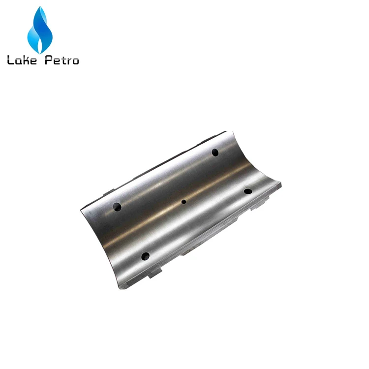
mud pump slide lower factory

Central lubrication manifold system with Stainless Steel tubing for feeding all main, eccentric, and pinion bearings. Pressurized lubrication is also provided to the upper and lower crosshead slide for longer crosshead life

Our primary purpose is to give our shoppers a serious and responsible company relationship, giving personalized attention to all of them for Mud Pump Slide Lower, Inflatable Tent Air Valve, H-Beam Connecting Rod, Engine Connecting Rods,Precision Brass Turning. Our items have exported to North America, Europe, Japan, Korea, Australia, New Zealand, Russia and other countries. On the lookout ahead to make up a good and long-lasting cooperation with you in coming potential! The product will supply to all over the world, such as Europe, America, Australia,Jordan, Yemen,Oman, Jordan.Whether selecting a current product from our catalog or seeking engineering assistance for your application, you can talk to our customer service center about your sourcing requirements. We can provided good quality with competitive price for you.

VigorPetro offers a full line of premium expendables and service parts for all well-known makes and models of mud pumps that are currently in operation worldwide.
These parts combine the finest materials and manufacturing expertise, including the premium service and support that VigorPetro has historically provided all our clients. The result is the best performing products available from any manufacturer. Whether you are running Brewster, Emsco, Ideco, Gardner-Denver, National, Oilwell, LEWCO, or Wirth pumps in your rig feet, VigorPetro is now a one-stop shop that can supply all the parts needed to keep these pumps running daily.
Spare parts:Upper and lower Valve Guide, Liner Gasket, Piston Rod, Rod Clamp, Valve Cover, Valve Cover Seal, Cylinder head, Cylinder Head Gasket, Cylinder Head Flange/Threaded Ring, Alignment Ring, Wear Plate, Cylinder Head Plug, Liner Flange, Liner Lock, Mud Baffle
Pony Rod/Extension Rod, Stuffing Box, Stuffing box Seal Parts, Crosshead, Crosshead Guide, Crosshead Pin, Crosshead Bearing, Connection Rod, Bull Gears, Pinion Shaft, Pinion Shaft Bearing/Bearing Carrier/Oil Seal Gasket/, Crank Shaft, Crank Shaft Bearing/Bearing Carrier, Eccentric Bearing, Inner/outer Race Retainer, Gauges, Oil Lubrication Pump, Mud Pump Transmission Belt Pulley/V-belt

Whether onshore or offshore, well drilling sites rely on a multitude of systems to successfully perform the drilling operation. The mud pump is a key component tasked with circulating drilling fluid under high pressure downhole. The mud pump can be divided into two key sections: the power end or crosshead and the fluid end. Proper alignment of the pump’s crosshead to the fluid end liner is necessary to maximizing piston and liner life. Misalignment contributes to
accelerated wear on both the piston and the liner, and replacing these components requires downtime of the pump. Traditional methods of inspecting alignment range from using uncalibrated wooden rods, Faro Arms and micrometers to check the vertical and horizontal alignment of the piston rod OD to the piston liner ID. These are time consuming and cumbersome techniques that are ultimately not well suited to troubleshoot and solve alignment issues.
A “Mud Pump Laser Alignment Kit” enables you to measure where the piston will run through the liner at various positions along the pump’s stroke. It will also project a laser centerline from the fluid end back towards the rear power end of the pump that can be used to determine how much shimming is required to correct any alignment issues. The kit can include either a 2-Axis receiver or a 4-Axis which accepts the laser beam and documents where it falls on the active surface of the receiver. The 4-Axis receiver can decrease alignment time by as much as 50% as it will measure angularity as well as X and Y while the 2-Axis does not and will need multiple measurement locations to get the same information. In addition, the alignment system is a non-intrusive service requiring the removal of only the piston rod which allows for much quicker service and less down time on the pump. As the mud pumps in question are located globally both on and offshore, having a small, portable system is another great advantage. Our recommendation would be Pinpoint laser System’s “Mud Pump Alignment Kit”. They are being used by many of the leading repair service companies and have been their main alignment tool for over 15 years. Manufacturers are also utilizing these for new pump set-up.
NexGen Manufacturing & Supply keeps a wide variety of replacement parts in stock for mud pumps, plunger pumps, swivels, top drives, handling tools, and much more! Additionally, we have more than 3,000 prints and drawings of oilfield equipment and
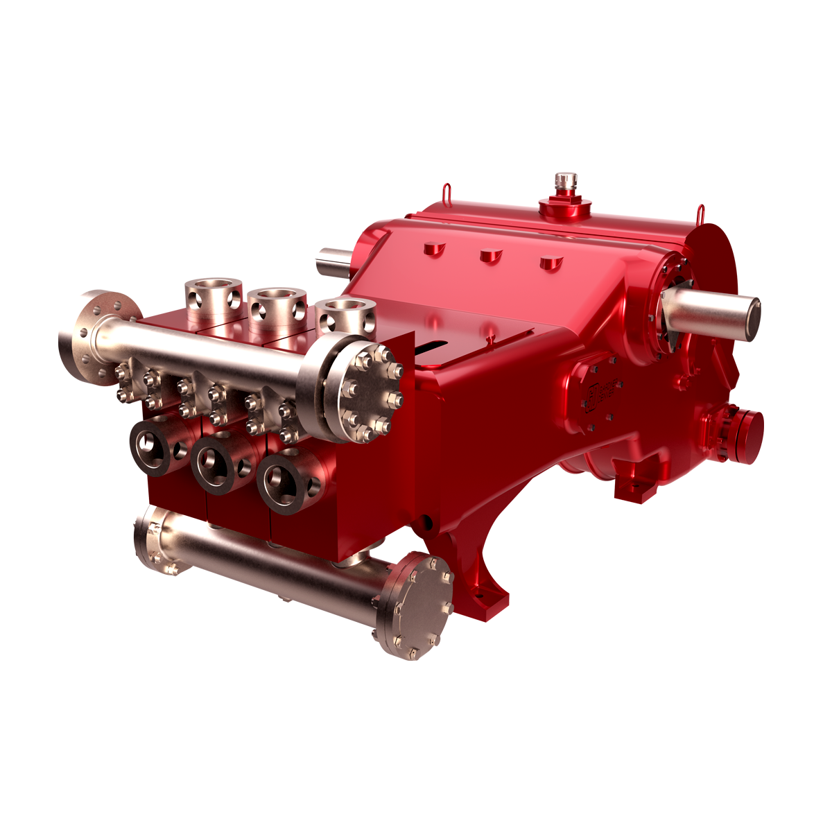
The 2,200-hp mud pump for offshore applications is a single-acting reciprocating triplex mud pump designed for high fluid flow rates, even at low operating speeds, and with a long stroke design. These features reduce the number of load reversals in critical components and increase the life of fluid end parts.
The pump’s critical components are strategically placed to make maintenance and inspection far easier and safer. The two-piece, quick-release piston rod lets you remove the piston without disturbing the liner, minimizing downtime when you’re replacing fluid parts.
This application claims priority under 35 U.S.C. § 119 to Canadian Patent Application No. 3,043,739, entitled “Mud Pump,” filed on May 17, 2019, in the name of Gerald Lesko; which is hereby incorporated by reference for all purposes. TECHNICAL FIELD OF THE INVENTION
The present disclosure is related to the field of pumps in general and, in particular, pumps used in pumping drilling mud or “mud pumps”. BACKGROUND OF THE INVENTION
It is known to use pumps to provide drilling mud under pressure in the drilling of wells. Pressurized drilling mud is delivered down a hollow drill string as the well is being drilled to carry away cuttings up the annulus surrounding the drill string to ground level. Such drilling operations are well known to those skilled in the art.
Prior art pumps can use a motor to turn a crankshaft or “pump shaft” to convert rotary motion to a reciprocating motion. The pump shaft moves a connecting rod coupled to a crosshead that moves within a fixed crosshead slide to provide this conversion. The crosshead is coupled to a “pony rod” that provides the pumping motion in a pump fluid end module, as well known to those skilled in the art.
The above-mentioned mechanical arrangement can be multiplied so that a multitude or plurality of pump fluid end modules can be operated from a single pump shaft. The output of each pump fluid end module can be coupled to a common manifold from which pressurized drilling mud can be provided to the drill string. By coupling the pump fluid end module outputs to a common manifold, the pulsing of the pressure of the drilling mud can be reduced or smoothed out, this being a problem well known to those skilled in the art. The disadvantage of this mechanical arrangement is the size and complexity of the components involved to provide a multi-module pump.
It is also known in the oil and gas industry to drill horizontal wells. These are wells that are initially drilled vertically and, with the use of directional drilling equipment as well known to those skilled in the art, the direction of drilled well becomes horizontal or parallel with the ground surface. It is known to drill horizontal wells up to 5486 meters (18000 feet) in length or more. To do so requires the use of “mud motors”, motors that are powered by the delivery of highly pressurized drilling mud pumped through the drill string so as to enable the turning of the drill bit. It is also known that to drill such wells, drilling operators will use at least two or more conventional mud pumps powered by 1000 horsepower or more motors. Each mud pump can be housed in its own pump house and occupies space at the drilling site. As each additional pump house increases the number of structures at a drilling site, the number of truckloads required to deliver the necessary equipment to a drilling site also increases. All this additional equipment and number of truckloads to deliver the equipment add cost to the drilling of the well.
In prior art mud pumps, an example of which is shown in FIG. 1, where bronze plates are used as the bearing surfaces for the horizontal side to side movement of the internal mechanism, an unwanted vertical force applies to the internal mechanism as a result of the crankshaft torque. This can cause undue and accelerated wear and friction on the bronze plates and to the pony rod bushings.
It is, therefore, desirable to provide a pump that can deliver pressurized mud at a volume equivalent to two or more conventional mud pumps without the shortcomings of the prior art technology. SUMMARY OF THE INVENTION
A pump is provided that comprises a pump shaft having at least one eccentric lobe that is substantially circular. A motor is used to provide the rotational power to the pump shaft. In one embodiment, the motor can be coupled directly to the pump shaft. In another embodiment, a transmission can be used between the motor and the pump shaft to reduce the angular speed of the rotational power provided to the pump shaft. In a representative embodiment, a one or multi-stage transmission can be used as well known to those skilled in the art. In a further embodiment, the motor can be a 3-phase AC motor controlled by a variable frequency drive mechanism to control the speed of the motor.
In one embodiment of the pump, the eccentric lobe can be rotatably disposed within a connecting rod having a substantially circular opening to receive the lobe at one end with the other end rotatably pinned to a slide configured to move in a horizontal and linear manner. In one embodiment, the slide can roll along a support wheel, wherein the wheel ca support the slide to counter the effects of the downward vertical force caused by the crankshaft torque as the slide moves in a linearly and horizontal or side-to-side manner. In one embodiment, the support wheel can be rotatably disposed on an axle coupled to the supporting frame so that the slide can move side-to-side with minimal friction. In another embodiment, the support wheel can roll along a lower track disposed on the bottom of the support frame, wherein the lower track can comprise means for adjusting a loading force on the support wheel against the slide to minimize any gap therebetween so that the slide is constrained to horizontal and linear movement. The support wheel can also center the pony rod in its housing and minimize wear on a wear band deposed therein.
As the lobe rotates within the connecting rod opening, the connecting rod slide can move up and down thereby moving the slide linearly and horizontally along the support wheel. As the slide frame moves side to side, it can move a pony rod in and out to operate a pump fluid end module. By virtue of this configuration, the slide can have a pony rod operatively coupled to one or both opposing sides of the slide. Therefore, a single slide can operate one or two pump fluid end modules at the same time. In a further embodiment, the pump shaft can comprise a plurality of eccentric lobes thereby allowing a plurality of slides to be operated by the lobes and, hence, a plurality of pump fluid end modules to be operated from a single rotating pump shaft.
Broadly stated, in some embodiments, a mud pump is provided, comprising: a frame; at least one pump fluid end module disposed on the frame, the at least one pump fluid end module comprising an inlet port and an outlet port; a pump shaft rotatably disposed in the frame for receiving rotational power from a motor, the pump shaft having at least one substantially circular eccentric lobe disposed thereon, the centre of the at least one eccentric lobe displaced or offset from the longitudinal axis of the pump shaft; at least one slide disposed in the frame, the at least one slide operatively configured to move linearly side-to-side within the frame; at least one pony rod assembly operatively coupling the at least one slide to the at least one pump fluid end module; and a connecting rod comprising first and second ends operatively coupling the pump shaft to the at least one slide, the first end rotatably disposed on the at least one eccentric lobe, the second end rotatably pinned to the at least one slide whereby rotation of the pump shaft causes the slide to move side-to-side that, in turn, causes the at least one pony rod assembly to operate the at least one pump fluid end module; and a support mechanism disposed beneath and operatively coupled to the at least one slide, the support mechanism rotatably coupled to the frame.
Broadly stated, in some embodiments, a mud pump is provided, comprising: a platform; a lattice frame disposed on the platform; at least one pump fluid end module disposed on the frame, the at least one pump fluid end module comprising an inlet port and an outlet port; a pump shaft rotatably disposed in the frame for receiving rotational power from a motor, the pump shaft having at least one substantially circular eccentric lobe disposed thereon, the centre of the at least one eccentric lobe displaced or offset from the longitudinal axis of the pump shaft; a motor operatively coupled to the pump shaft, the motor disposed on the platform; at least one slide disposed in the frame, the at least one slide operatively configured to move linearly side-to-side within the frame; at least one pony rod assembly operatively coupling the at least one slide to the at least one pump fluid end module; and a connecting rod comprising first and second ends operating coupling the pump shaft to the at least one slide, the first end rotatably disposed on the at least one eccentric lobe, the second end rotatably pinned to the at least one slide whereby rotation of the pump shaft causes the slide to move side-to-side that, in turn, causes the at least one pony rod assembly to operate the at least one pump fluid end module; and a support mechanism disposed beneath and operatively coupled to the at least one slide.
Broadly stated, in some embodiments, the support mechanism can comprise a support wheel rotatably disposed beneath the at least one slide, the at least one slide configured to roll along on top of the support wheel.
Broadly stated, in some embodiments, the anti-skidding engagement mechanism can comprise a plurality of anti-skidding balls disposed on one of the support wheel and the at least one slide, and a plurality of corresponding pockets disposed on the other of the support wheel and the at least one slide.
Broadly stated, in some embodiments, the plurality of anti-skidding balls can be disposed around a circumference of the support wheel and the plurality of corresponding pockets are disposed along a lower edge of the at least one slide.
Broadly stated, in some embodiments, the support wheel can be rotatably disposed on an adjuster mechanism, the adjuster mechanism comprising a fixed wedge and an overlapping moving wedge, the combination of which can raise or lower the support wheel relative to the at least one slide.
Broadly stated, in some embodiments, the plurality of anti-skidding balls can be disposed along a lower edge of the at least one slide and the plurality of corresponding pockets are disposed around a circumference of the support wheel.
Broadly stated, in some embodiments, the mud pump can further comprise transmission operatively disposed between the motor and the pump shaft thereby coupling the motor to the pump shaft.
Broadly stated, in some embodiments, the mud pump can further comprise an intake manifold operatively coupled to the inlet port of the at least one pump fluid end module, the intake manifold providing communication between an intake manifold inlet and the inlet port of the at least one pump fluid end module.
Broadly stated, in some embodiments, the mud pump can further comprise an outlet manifold operatively coupled to the outlet port of the at least one pump fluid end module, the outlet manifold providing communication between the outlet port of the at least one pump fluid end module and an outlet manifold outlet.
Broadly stated, in some embodiments, the at least one pony rod assembly can further comprise: a pony rod support bushing configured to be disposed on the frame; a piston liner comprising first and second ends, the second end operatively coupled to the at least one pump fluid end module; and a pony rod slidably disposed in the support bushing, the pony rod comprising first and second ends, the first end operatively coupled to the at least one slide, the second end further comprising a piston slidably disposed in the piston liner thereby forming a liner chamber disposed between the piston and the support bushing.
Broadly stated, in some embodiments, the pony rod assembly can further comprise: a pony rod support bushing configured to be disposed on the frame; a stuffing box disposed in the at least one pump fluid end module; and a pony rod slidably disposed in the support bushing, the pony rod comprising first and second ends, the first end operatively coupled to the at least one slide, the second end further comprising a plunger slidably disposed in the stuffing box.
Broadly stated, in some embodiments, the mud pump can further comprise a pump house wherein the mud pump is disposed in the pump house. BRIEF DESCRIPTION OF THE DRAWINGS
Referring to FIGS. 2 to 14, one embodiment of a mud pump is illustrated. In this embodiment, mud pump 10 can comprise lattice frame 18 and pump fluid end modules 24 mounted thereon. Frame 18 can further comprise mounting tabs 14 for attaching mud pump 10 to a platform, to a skid or to a pump house.
For the purposes of this specification, and as shown specifically in the figures, each pump fluid end module 24 can comprise inlet port 25, outlet port 35, top access port 37 (shown as 37aand 37bin FIGS. 6 and 7) and side access port 36 (shown as 36aand 36bin FIGS. 6 and 7). Pump fluid end module 24, as illustrated, can be any suitable pump fluid end module that is readily available to the mud pump industry and is well known to those skilled in the art. As shown in FIG. 2, pump fluid end module 24 is shown as a singular device having three pump units disposed therein (shown as 24ain FIG. 7). It is obvious to those skilled in the art that pump fluid end module 24 can comprise one or more pump units use in combination. Representative examples of pump fluid end module 24 are pump fluid end modules having an 800 horsepower rating as manufactured by Continental Emsco in the U.S.A. or their equivalent. Such pumps have interchangeable liners of different diameters whereby the volume of mud handled by a pump fluid end module per pump cycle can be adjusted upwards or downwards depending on the diameter of the liner. Generally speaking, the smaller the volume per pump fluid end module, the greater the pressure the mud can be pumped at.
Referring to FIG. 2, mud pump 10 is shown having cover 20 disposed on top of lattice frame 18. Input shaft 12 can be connected to a motor (not shown) to provide rotational input power to mud pump 10. In some embodiments, an internal combustion motor can be used to provide rotational input power to mud pump 10. In other embodiments, an electric motor of suitable power rating can be used. In further embodiments, a variable frequency drive mechanism (not shown) as well known to those skilled in the art can be used to control the electrical power provided to the electric motor thereby controlling the rotational speed the motor operates at to supply rotational input power to mud pump 10.
In one embodiment, mud pump 10 can comprise transmission 22 to couple shaft 12 to the operating components of mud pump 10. Transmission 22 can be a single-stage or multi-stage transmission to reduce the rotational speed of input shaft 12 to the required rotational speed for proper operation of pump shaft 30 rotatably disposed in mud pump 10. In other embodiments, transmission 22 can comprise a planetary gear transmission. In further embodiments, transmission 22 can comprise helical gears. In yet other embodiments, transmission 22 can comprise spur gears. Intake manifold 52, comprising inlet 54, is shown attached to pump fluid end module inlet ports 25 (shown as 25aand 25bin FIGS. 6 and 7). Outlet manifold 58, comprising couplers 62 and end caps 66, is shown attached to pump fluid end module outlet ports 35.
Referring to FIG. 3, a rear elevation view of mud pump 10 is shown. In this figure, pony rod support bushings 31 are shown disposed on sidewalls 19 of frame 18 (shown as 31aand 31bin FIGS. 6 and 7).
Referring to FIGS. 4 and 5, front views of mud pump 10 are shown. In one embodiment, pump fluid end module 24 can comprise “sucker-cup” pump mechanisms as well known to those skilled in the art. In the illustrated embodiment, an output manifold (not shown) can be attached to the shown outlet ports 35 to collect drilling mud pumped by pump fluid end module 24, in addition to outlet manifold 58 shown in FIGS. 2 and 3, or it can be capped with a cover (not shown). Input ports 25 can be coupled together with intake manifold 52 that directs drilling mud into pump fluid end modules 24.
Referring to FIGS. 6 and 7, front cross-section views of mud pump 10 are shown revealing the internal components of the embodiment shown therein. In this embodiment, pump shaft 30 rotates as a result of input rotational power applied to input shaft 12 that is operatively coupled to pump shaft 30 via transmission 22 as shown in FIG. 5. In one embodiment, pump shaft 30 can comprise eccentric 80 disposed thereon. Rotatably disposed on eccentric 80 is connecting rod 84. In another embodiment, eccentric bearing 83 is disposed between eccentric 80 and connecting rod 84. In a further embodiment, connecting rod 84 is rotatably pinned to sidewall 28b(and to sidewall 28aas shown in FIG. 10) of slide via pin 86. In yet another embodiment, bearing 85 can be disposed between pin 86 and connecting rod 84. Mud pump 10 can comprise at least one sight glass 21 to permit visual inspection therein, as shown in FIGS. 2 to 7.
In FIG. 6, eccentric 80 is shown rotating clockwise thereby moving connecting rod 84 to the right in this figure. In so doing, slide 28 is being pushed to the right. In some embodiments, mud pump 10 can comprise a support mechanism configured for countering the unwanted vertical force as described above and shown in FIG. 1. In some embodiments, the support mechanism can comprise support wheel 120 disposed beneath slide 28 whereupon slide 28 can roll along on top of support wheel 120. As shown in more detail in FIGS. 8A and 8B, support wheel 120 can be comprised of tubular-shaped hub 130. As shown in FIGS. 6, 7 and 9 to 14, wheel 120 can be rotatably disposed on axle 126 disposed between sidewalls 28aand 28bof slide 28. In some embodiments, bushing 124 can be disposed between axle 126 and wheel 120 as a bearing to minimize friction as wheel 120 rotates on axle 126.
In some embodiments, the support mechanism can comprise an anti-skidding engagement mechanism with slides 28. In some embodiments, the anti-skidding engagement mechanism can comprise a plurality of anti-skidding balls 122 disposed around the circumference of hub 130 of wheel 120 in a substantially equally spaced-apart configuration. In some embodiments, wheel 120 can comprise two such sets of the plurality of anti-skidding balls 122, one disposed near each end of hub 130. In embodiments, anti-skidding balls 122 can be comprised of spheres of steel or similarly hard material. In some embodiments, a series of holes 136 can be drilled through hub 130, then a concave pocket can be drilled or machined on the outer surface of hub 130 at each hole 136 wherein each of the concave pockets is configured to receive an anti-skidding ball 122. Each hole 136 can then be tapped so as to be able to receive set screws 134, in a manner well known to those skilled in the art. Similarly, each anti-skidding ball 122 can be drilled and tapped to receive a set screw 134. In some embodiments, to assemble 120, the anti-skidding balls 122 are placed in the concave pockets disposed on hub 130 and then secured thereto by set screw 134 being through hole 136 into anti-skidding ball 122, with each set screw 134 being tightened so that anti-skidding balls 122 are secured to hub 130. In some embodiments, set screws 134 can be further secured using a thread-locking liquid, such as Loctite® or similar substance as well known to those skilled in the art. In some embodiments, after anti-skidding balls 122 have been attached to hub 130, bushing 124 can then be pressed into the interior opening of hub 130, in a manner as well known to those skilled in the art.
In some embodiments, one or both of sidewalls 28aand 28bcan comprise track 128 disposed along a lower edge thereof, each track 128 comprising a plurality of substantially equally spaced-apart pockets 138 (as shown in FIG. 8C) wherein the spacing of pockets 138 substantially corresponds to the spacing of anti-skidding balls 122 disposed around wheel 120. When slide 28 is assembled into frame 18, pockets 138 on each track 128 can be fitted on corresponding anti-skidding balls 122 on wheel 120 such that slide 28 can roll along wheel 120 in a horizontal linear path from left to right and vice-versa. This configuration can further resist the bending moment caused by the rotation of pump shaft 30 and eccentric 80 as wheel 120 can counter the unwanted vertical force as shown in FIG. 1 in the prior art mud pump. In the illustrated embodiment, each of sidewalls 28aand 28bcomprises a track 138 for engaging corresponding anti-skidding balls 122 disposed around a single wheel 120. In other embodiments, it is possible that only one of sidewall 28aand 28bcan comprise a track 138, with corresponding anti-skidding balls 122 disposed around one end of hub 130 of wheel 120. In other embodiments, it possible that more than one support wheel 120 can be implemented to counter the unwanted vertical force that can be imparted on slide 28. In other embodiments, the anti-skidding engagement mechanism can comprise alternate mechanisms for the engagement between slide 28 and support wheel 120, which can comprise but are not limited to straight-cut gear teeth similar to a rack and pinion system as well known to those skilled in the art, angle-cut gear teeth, chain and sprocket profiles disposed onto wheel 120 and lower edge of slide 28, v-shaped profiles disposed onto wheel 120 and lower edge of slide 28, anti-skid elastomeric or rubber material disposed on wheel 120 and lower edge of slide 28, a rail channel disposed on either of wheel 120 and slide 28 wherein one of wheel 120 and slide 28 can be disposed within the rail channel disposed on the other of wheel 120 and slide 28, as well as any other anti-skidding engagement mechanism as well known to those skilled in the art.
Referring to FIG. 6, as slide 28 moves to the right, it pushes pony rod 27aand, hence, plunger 40ato the right in stuffing box 26ato push fluids in pump chamber 42aout through valve 39aoto outlet ports 35 (not shown) and outlet manifold 58 (not shown). In so doing, pony rod 27balso pulls plunger 40bin stuffing box 26bto the right thereby drawing in fluid through valve 39bifrom intake manifold 52.
In FIG. 7, eccentric 80 is shown rotated further clockwise (from FIG. 6) thereby moving connecting rod 84 to the left. In so doing, plunger 40ais being pulled to the left thereby drawing in fluid into pump chamber 42athrough valve 39aifrom intake manifold 52 while plunger 40bis pushed to the left thereby pushing fluid out of pump chamber 42bthrough valve 39boto outlet ports 35 (not shown) and outlet manifold 58 (not shown).
Referring to FIG. 9, mud pump 10 is shown without pump fluid end modules 24, cover 22, piston liners 26, pump shaft 30 and connecting rods 84. In this illustrated embodiment, frame sidewalls 19 are visible as are removable caps 17, which are configured hold pump shaft 30 in place in frame 18. In some embodiments, retainer caps 15 can be attached to the outer walls of frame 18 to further secure removable caps 17. With respect to interior walls 16, removable caps 17 can further secured thereto with straps 112 with threaded fasteners 114. With this configuration, caps 117 can add strength and stiffness to frame 18.
Referring to FIG. 10, the mud pump 10 of FIG. 9 is now shown with frame 18 removed to reveal slides 28. In some embodiments, each slide 28 can comprise a pair of substantially parallel spaced-apart sidewalls 28aand 28b, as shown in FIGS. 10 to 14. In some embodiment, each slide 28 can comprise openings 29 disposed through sidewalls 28aand 28bfor pump shaft 30 (not shown) to pass through and pin boss 88 disposed through sidewalls 28aand 28bthat are configured to receive connecting rod pins 86.
Referring to FIG. 15A, a cross-section view is shown of a piston embodiment of the internal pumping mechanism of mud pump 10. In some embodiments, pony rod 27 can be coupled to slide 28 by placing pony rod 27 into opening 91 disposed on slide 28. In some embodiments, pony rod 27 can be further secured with pin 101 disposed on slide 28, wherein pin 101 is configured to fit within opening 103 disposed in pony rod 27 to prevent rotation thereof in opening 91. In some embodiments, pony rod stud 92 can be disposed in an opening disposed through pony rod 27 and secured to slide 28 in threaded opening 93. In some embodiments, pony rod stud 92 can further comprise flange 95 that can rest against shoulder 94 disposed within pony rod 27. In some embodiments, piston rod 96 can be threaded into threaded opening 109 of pony rod 27, wherein rod 96 can comprise flange 105 upon which piston 40 can be secured thereto by nut 98 threaded onto threaded end 107 of rod 96. Washer 97 can be sandwiched between nut 98 and rod 96.
In some embodiments, mud pump 10 can comprise means for circulating coolant in piston liner 26 behind piston 40 to prevent overheating of the mechanism when in operation. As shown in FIG. 15A, coolant can be pumped by a coolant pump (not shown) into liner chamber 106 through coolant inlet 102 disposed in coupler 41 via lines, hoses or piping (not shown). Coolant can the flow through, and circulate within, chamber 106 and then exit through coolant outlet 104. Lines, hoses and piping (not shown) can be coupled to outlet 104 so that the heated coolant can be collected, cooled and re-circulated, all as well known to those skilled in the art. In some embodiments, inlet 102 and outlet 104 can further comprise one-way valves, such as ball-valves as one example obvious to those skilled in the art, such that coolant can be drawn into chamber 106 through inlet 102 as piston 40 is moving towards pump fluid end module 24 (not shown), and then expelled from chamber 106 through outlet 104 and piston 40 is moving away from pump fluid end module 24.
In some embodiments, mud pump 10 can comprise means for circulating lubricating oil to pony rod 27 as it reciprocates back and forth through support bushing 31. As shown in FIG. 15A, with the pump module labelled as 24aand piston 40 slidably disposed in pump chamber 42, lubricating oil can be pumped by an oil pump (not shown) into oil inlet 108 where it can flow into annulus 110 between pony rod 27 and support bushing 31 thereby maintaining a layer of lubricating oil therebetween. Oil can then flow out of annulus 110 into galleys 38 (as shown in FIG. 2) where the oil can be collected and re-circulated. In some embodiments, barrier seals 99 and ice-breaker wear band 100 can be disposed between pony rod 27 and support bushing 31 as sealing means to separate and isolate chamber 106 from annulus 110 so that coolant does not intermingle with and contaminate the lubricating oil, and vice-versa.
Referring to FIG. 15B, a cross-section view is shown of a plunger embodiment of the internal pumping mechanism of mud pump 10. In some embodiments, pony rod 27 can be coupled to slide 28 by placing pony rod 27 into opening 91 disposed on slide 28. In some embodiments, pony rod 27 can be further secured with pin 101 disposed on slide 28, wherein pin 101 is configured to fit within opening 103 disposed in pony rod 27 to prevent rotation thereof in opening 91. In some embodiments, pony rod stud 92 can be disposed in an opening disposed through pony rod 27 and secured to slide 28 in threaded opening 93. In some embodiments, pony rod stud 92 can further comprise flange 95 that can rest against shoulder 94 disposed within pony rod 27. In some embodiments, threaded stud 221 of plunger 220 can be threaded into threaded opening 109 of pony rod 27. In this embodiment, pump module 24bcan comprise stuffing box 222 disposed in opening 223 of pump module 24b. Stuffing box 222 can further comprise one or more circumferential seals 224 disposed therein to seal around plunger 220 as it reciprocates in and out of stuffing box 222.
Referring to FIG. 16, an alternate embodiment of the support mechanism for use with improved mud pump 10 is shown. In this embodiment, the support mechanism can comprise of support wheel 140 configured to disposed and roll between upper track 142, disposed on a lower surface of slide 28, and lower track 144, disposed on adjuster mechanism 146 that is further disposed on bottom plate 8. Wheel 140 can comprise of a similar construction as wheel 120, comprising a plurality of anti-skidding balls, as described herein, disposed around the circumference of wheel 140 and corresponding pockets disposed along upper track 142 and lower track 144. Alternatively, each upper track 142 and lower track 144 can comprise anti-skidding balls disposed therealong with corresponding pockets disposed around the circumference of wheel 140. To adjust the lash or clearance between wheel 140 and slide 28, adjuster mechanism 146 can raise or lower wheel 140 in relation to slide 28 to minimize the clearance therebetween and to center pony rods 27 in support bushings 31. In some embodiments, adjuster mechanism 146 can comprise of wedge 148 and overlapping wedge 150, wedge 148 operatively coupled to adjusting bolt 152, wherein lower track 144 can be disposed on top of wedge 150. By turning adjusting bolt 152 clockwise, as an example, wedge 148 can move towards to right thereby lifting wedge 150 to raise lower track 144 and, thus, wheel 140 towards upper track 142 to decrease the lash or clearance therebetween. By turning adjusting bolt 152 counter-clockwise, as an example, wedge 148 can move to the left thereby lowering wedge 150 to lower track 144 and, thus, wheel 140 away from upper track 142 to increase the lash or clearance therebetween.
Referring to FIG. 17, improved mud pump 10 is shown beside an example of prior art mud pump 160 having a similar pumping capacity to mud pump 10. It is apparent from this comparison that at least one advantage of improved mud pump 10 is a reduction of size of an equivalent performing mud pump, which can translate into a reduction of cost to an operator in terms of upfront material costs to manufacture the mud pump, a reduction of the cost to maintain the mud pump, a reduction of cost in moving the improved mud pump from site to site, a reduction of costs related to the operation of the mud pump and, at least, a reduction of space required at a site when the improved mud pump is positioned for pumping mud.
In the embodiments illustrated the figures herein, there are three slides 28 shown, each coupled to two opposing pump fluid end modules 24 thereby resulting in the operation of six pump fluid end modules. It is obvious to those skilled in the art that fewer or more slides mechanisms can be implemented to either decrease or increase the number of pump fluid end modules that can be operated. As an example, and as shown in FIG. 20, mud pump 10 can comprise 5 pump fluid end modules 24 a side, or ten in total. It is also obvious to those skilled in the art that a slide frame can be releasably coupled to a single pony rod to, therefore, operate a single pump fluid end module.
Referring to FIG. 2, mud pump 10 is shown in a triplex configuration, wherein each side of mud pump 10 operates three pump fluid end modules 24 thus requiring pump shaft 30 to rotate three connecting rods 84. This necessarily requires pump shaft 30 having three eccentric lobes 80. In this configuration, the lobes can be displaced nominally 120° apart from each other such that the lobes can be substantially spaced equally apart around the circumference of pump shaft 30. In embodiments where pump shaft 30 comprises two eccentric lobes 80, the lobes can be displaced nominally 180° apart. In other embodiments where pump shaft 30 comprises two lobes 80, one lobe 80 can be displaced 178° from the other lobe 80 so that pump shaft 30 can more easily turn from a dead stop. In other embodiments where additional eccentric lobes are disposed on pump shaft 30, the lobes can be substantially spaced equally apart on pump shaft 30. For example, for a four-lobe shaft, each lobe 80 can be displaced 90° nominally from each other lobe 80. If five lobes are disposed on pump shaft 30, the lobes can be displaced nominally 72° apart on pump shaft 30, as would be the case for the embodiment of mud pump 10 shown in FIG. 20. For six lobes disposed on pump shaft 30, the lobes can be displaced nominally 60° apart, and so on as well known to those skilled in the art.
In operation, mud can be supplied to inlet 54 on intake manifold 52 from an external pump (not shown) drawing mud from a mud tank (not shown) as well known to those skilled in the art. As slides 28 operate pump fluid end modules 24, mud is drawn into pump fluid end modules 24 from intake manifold 52 and pumped out of pump fluid end modules 24 into outlet manifold 58 via outlet manifold couplers 62 disposed between pump fluid end modules 24 and outlet manifold 58. The pumped mud can exit outlet manifold 58 via outlet 60 that can be connected to a mud delivery pipe and/or hose for use on a drilling rig (not shown) as well known to those skilled in the art. In one embodiment, the diameter of inlet 54 and the pipe that make up intake manifold 52 can be nominally ten inches whereas the diameter of outlet and the pipe that make up outlet manifold 58 can be nominally four inches. In another embodiment, outlet manifold 58 can comprise couplings (as shown in FIG. 4) for connection with pressure gauge 33 to provide a visual indication of the pressure of the mud being pumped and/or a pressure relief valve to provide means to limit the pressure of the mud being pumped by mud pump 10. It is obvious to those skilled in the art that the diameters of inlet 54, intake manifold 52, outlet manifold 58 or outlet 60 can be increased or decreased depending on the volume and pressure of drilling mud required in the drilling of a well.
In operation, it is expected that mud pump 10 can operate up to 200 revolutions, which translates up to 400 pump fluid end module strokes per minute per slide frame mechanism given that each slide frame can be coupled to two pump fluid end modules. Given an input power up to 3000 horsepower, it is anticipated that mud pump 10 can pump up to 750 gallons or 3.75 cubic meters of drilling mud per minute at up to 7500 pounds per square inch of pressure. It is also expected that mud pump 10 would weigh approximately 45,000 pounds including the motor and all other related equipment required to pump drilling mud at the equivalent volume and pressure of drilling mud as a conventional mud pump powered by the same motor but weighing up to 120,000 pounds.
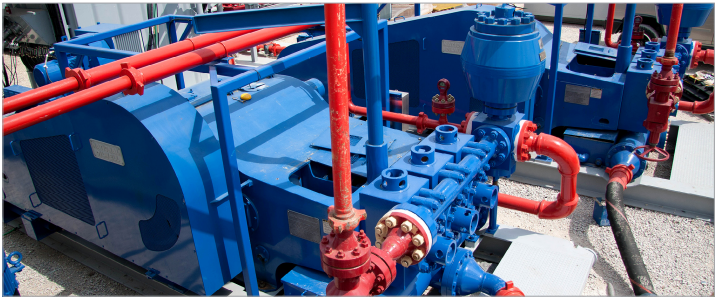
Referring to FIG. 18, mud pump 10 is shown positioned in pump house 56, a structure used to house mud pumps at drilling sites. Access to mud pump 10 is done through doorways 64. In this configuration, mud pump 10 can be positioned “lengthwise” in pump house 56.
Referring to FIG. 19, mud pump 10 is shown in pump house 56 rotated 90 degrees as compared to the embodiment shown in FIG. 18. The compactness of mud pump 10 can allow it to be installed in this manner in pump house 56 whereby access to the inlet and outlet to mud pump 10 is through doorway 64. In addition, more than one mud pump 10 can be installed in pump house 56 thereby reducing the number of pump houses required at a drilling site if the well being drilled requires a volume of pressurized drilling mud greater than what one mud pump 10 can provide.
Referring to FIG. 21, another embodiment of a support wheel mechanism can be provided for retro-fitting a conventional mud pump, represented by reference character 200. In some embodiments, support wheel 208 can be rotatably disposed on axle 210, further disposed within the body of prior art mud pump 200, wherein opening 206 is made in liner 204 so as to enable crosshead 202 to roll along wheel 208 similar to how slide 28 can roll along wheel 120 or wheel 140 in the embodiments described above. In some embodiments, wheel 140 can comprise the anti-skidding balls disposed therein, which can be configured to fit within pockets along crosshead 202. Alternatively, a plurality of anti-skidding balls can disposed along cross crosshead 202 with corresponding pockets disposed around the circumference of wheel 208.

Houston, Texas -- To eliminate equipment compatibility issues and the prospect of additional spare-parts inventories for drilling contractors, the LeTourneau Ellis Williams Company (LEWCO) can factory-equip its heavy-duty W-Series and general-duty WH-Series mud pumps with virtually any major brand of fluid end module. Customers not specifying a particular brand receive LEWCO"s standard one-piece or two-piece fluid end modules made of quenched and tempered forged steel, featuring "off the shelf" expendables readily available from domestic and international sources.
LEWCO mud pumps are in-house manufactured. For maximum quality assurance -- with job-ready performance verified in advance -- every pump is tested under full load prior to shipment, in the company"s fully equipped, million-dollar "mud pump laboratory." LEWCO pumps provide input ratings of 300 to 3,000 horsepower (224 kW to 2,237 kW) and deep-drilling discharge pressures as great as 7,500 pounds per square inch (527 kg/cm2). Their premium components include a pressurized lubrication system that force-feeds lubricant to all power-end bearings including upper and lower crosshead slides; a balanced forged steel crankshaft that reduces noise and vibration and helps extend component life throughout the pump; and a robust frame of double-wall, welded-steel, mounted on a heavy-duty oilfield skid.
The LeTourneau Ellis Williams Company builds high-performance mud pumps for oil and gas drilling (on land and offshore), petroleum production and processing, well-servicing, and horizontal directional drilling; as well as ancillary drilling products including pulsation dampeners; drawworks; rotary tables, transmissions, and drives; and swivels. Located in Houston, Texas, LEWCO is a wholly owned subsidiary of LeTourneau Incorporated, a leading manufacturer of self-elevating offshore drilling rigs, forestry equipment, and wheel loaders.
For more information, contact the LEWCO Sales Department at 6500 Brittmoore Road, Houston, TX 77241-1343; telephone 1-888-MUD-PUMP (683-7867), fax 713-856-5341; e-mail pumps@lewco-equip.com. Or visit www.lewco-equip.com.

When choosing a size and type of mud pump for your drilling project, there are several factors to consider. These would include not only cost and size of pump that best fits your drilling rig, but also the diameter, depth and hole conditions you are drilling through. I know that this sounds like a lot to consider, but if you are set up the right way before the job starts, you will thank me later.
Recommended practice is to maintain a minimum of 100 to 150 feet per minute of uphole velocity for drill cuttings. Larger diameter wells for irrigation, agriculture or municipalities may violate this rule, because it may not be economically feasible to pump this much mud for the job. Uphole velocity is determined by the flow rate of the mud system, diameter of the borehole and the diameter of the drill pipe. There are many tools, including handbooks, rule of thumb, slide rule calculators and now apps on your handheld device, to calculate velocity. It is always good to remember the time it takes to get the cuttings off the bottom of the well. If you are drilling at 200 feet, then a 100-foot-per-minute velocity means that it would take two minutes to get the cuttings out of the hole. This is always a good reminder of what you are drilling through and how long ago it was that you drilled it. Ground conditions and rock formations are ever changing as you go deeper. Wouldn’t it be nice if they all remained the same?
Centrifugal-style mud pumps are very popular in our industry due to their size and weight, as well as flow rate capacity for an affordable price. There are many models and brands out there, and most of them are very good value. How does a centrifugal mud pump work? The rotation of the impeller accelerates the fluid into the volute or diffuser chamber. The added energy from the acceleration increases the velocity and pressure of the fluid. These pumps are known to be very inefficient. This means that it takes more energy to increase the flow and pressure of the fluid when compared to a piston-style pump. However, you have a significant advantage in flow rates from a centrifugal pump versus a piston pump. If you are drilling deeper wells with heavier cuttings, you will be forced at some point to use a piston-style mud pump. They have much higher efficiencies in transferring the input energy into flow and pressure, therefore resulting in much higher pressure capabilities.
Piston-style mud pumps utilize a piston or plunger that travels back and forth in a chamber known as a cylinder. These pumps are also called “positive displacement” pumps because they literally push the fluid forward. This fluid builds up pressure and forces a spring-loaded valve to open and allow the fluid to escape into the discharge piping of the pump and then down the borehole. Since the expansion process is much smaller (almost insignificant) compared to a centrifugal pump, there is much lower energy loss. Plunger-style pumps can develop upwards of 15,000 psi for well treatments and hydraulic fracturing. Centrifugal pumps, in comparison, usually operate below 300 psi. If you are comparing most drilling pumps, centrifugal pumps operate from 60 to 125 psi and piston pumps operate around 150 to 300 psi. There are many exceptions and special applications for drilling, but these numbers should cover 80 percent of all equipment operating out there.
The restriction of putting a piston-style mud pump onto drilling rigs has always been the physical size and weight to provide adequate flow and pressure to your drilling fluid. Because of this, the industry needed a new solution to this age-old issue.
As the senior design engineer for Ingersoll-Rand’s Deephole Drilling Business Unit, I had the distinct pleasure of working with him and incorporating his Centerline Mud Pump into our drilling rig platforms.
In the late ’90s — and perhaps even earlier — Ingersoll-Rand had tried several times to develop a hydraulic-driven mud pump that would last an acceptable life- and duty-cycle for a well drilling contractor. With all of our resources and design wisdom, we were unable to solve this problem. Not only did Miller provide a solution, thus saving the size and weight of a typical gear-driven mud pump, he also provided a new offering — a mono-cylinder mud pump. This double-acting piston pump provided as much mud flow and pressure as a standard 5 X 6 duplex pump with incredible size and weight savings.
The true innovation was providing the well driller a solution for their mud pump requirements that was the right size and weight to integrate into both existing and new drilling rigs. Regardless of drill rig manufacturer and hydraulic system design, Centerline has provided a mud pump integration on hundreds of customer’s drilling rigs. Both mono-cylinder and duplex-cylinder pumps can fit nicely on the deck, across the frame or even be configured for under-deck mounting. This would not be possible with conventional mud pump designs.
The second generation design for the Centerline Mud Pump is expected later this year, and I believe it will be a true game changer for this industry. It also will open up the application to many other industries that require a heavier-duty cycle for a piston pump application.


 8613371530291