
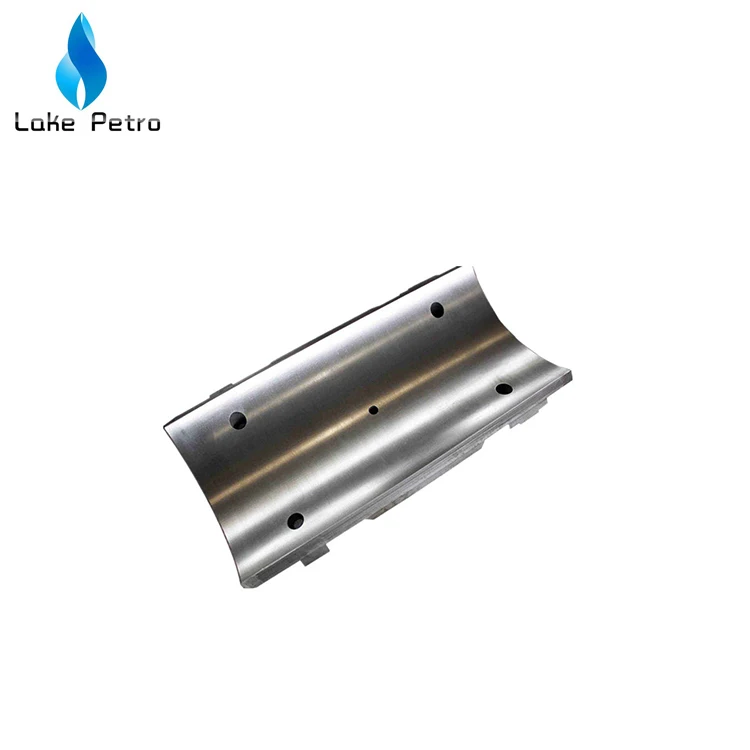
mud pump slide upper in stock
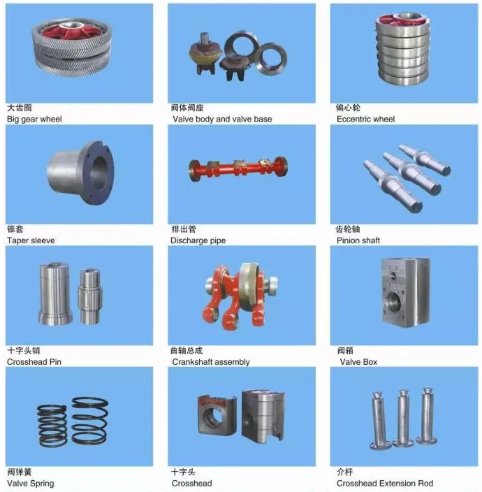
The Mud pump crosshead is the critical part on the power end of the mud pump. It slides in the upper and lower guide plates, motivating the intermediate draw bar to deliver driving force to the hydraulic end. One of its ends fixes the intermediate draw bar. The cavity connects the small end of the connecting rod through cross head pin.
The material of the mud pump crosshead is nodular cast iron with the strength of extension of more than 600MPa, which ensures high intensity and abrasive resistance.

Browse through more than 1,500 duplex piston rods and 200 duplex pony rods in our inventory. EC Tool gives you a quote before your order, so you know what you’re getting for your money every time. While we primarily keep connecting rods for GA550 and GA750 models in stock, there are other options at your disposal as well. This includes custom connecting rods for most duplex and triplex mud pumps.
We now offer new crossheads and capsules for both EMSCO D-375 and DB-550 duplex pumps. You can also find slides and shoes for certain models. Available parts currently in our inventory include:
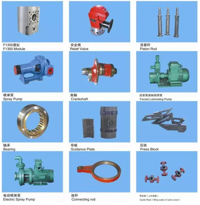
Central lubrication manifold system with Stainless Steel tubing for feeding all main, eccentric, and pinion bearings. Pressurized lubrication is also provided to the upper and lower crosshead slide for longer crosshead life
When choosing a size and type of mud pump for your drilling project, there are several factors to consider. These would include not only cost and size of pump that best fits your drilling rig, but also the diameter, depth and hole conditions you are drilling through. I know that this sounds like a lot to consider, but if you are set up the right way before the job starts, you will thank me later.
Recommended practice is to maintain a minimum of 100 to 150 feet per minute of uphole velocity for drill cuttings. Larger diameter wells for irrigation, agriculture or municipalities may violate this rule, because it may not be economically feasible to pump this much mud for the job. Uphole velocity is determined by the flow rate of the mud system, diameter of the borehole and the diameter of the drill pipe. There are many tools, including handbooks, rule of thumb, slide rule calculators and now apps on your handheld device, to calculate velocity. It is always good to remember the time it takes to get the cuttings off the bottom of the well. If you are drilling at 200 feet, then a 100-foot-per-minute velocity means that it would take two minutes to get the cuttings out of the hole. This is always a good reminder of what you are drilling through and how long ago it was that you drilled it. Ground conditions and rock formations are ever changing as you go deeper. Wouldn’t it be nice if they all remained the same?
Centrifugal-style mud pumps are very popular in our industry due to their size and weight, as well as flow rate capacity for an affordable price. There are many models and brands out there, and most of them are very good value. How does a centrifugal mud pump work? The rotation of the impeller accelerates the fluid into the volute or diffuser chamber. The added energy from the acceleration increases the velocity and pressure of the fluid. These pumps are known to be very inefficient. This means that it takes more energy to increase the flow and pressure of the fluid when compared to a piston-style pump. However, you have a significant advantage in flow rates from a centrifugal pump versus a piston pump. If you are drilling deeper wells with heavier cuttings, you will be forced at some point to use a piston-style mud pump. They have much higher efficiencies in transferring the input energy into flow and pressure, therefore resulting in much higher pressure capabilities.
Piston-style mud pumps utilize a piston or plunger that travels back and forth in a chamber known as a cylinder. These pumps are also called “positive displacement” pumps because they literally push the fluid forward. This fluid builds up pressure and forces a spring-loaded valve to open and allow the fluid to escape into the discharge piping of the pump and then down the borehole. Since the expansion process is much smaller (almost insignificant) compared to a centrifugal pump, there is much lower energy loss. Plunger-style pumps can develop upwards of 15,000 psi for well treatments and hydraulic fracturing. Centrifugal pumps, in comparison, usually operate below 300 psi. If you are comparing most drilling pumps, centrifugal pumps operate from 60 to 125 psi and piston pumps operate around 150 to 300 psi. There are many exceptions and special applications for drilling, but these numbers should cover 80 percent of all equipment operating out there.
The restriction of putting a piston-style mud pump onto drilling rigs has always been the physical size and weight to provide adequate flow and pressure to your drilling fluid. Because of this, the industry needed a new solution to this age-old issue.
As the senior design engineer for Ingersoll-Rand’s Deephole Drilling Business Unit, I had the distinct pleasure of working with him and incorporating his Centerline Mud Pump into our drilling rig platforms.
In the late ’90s — and perhaps even earlier — Ingersoll-Rand had tried several times to develop a hydraulic-driven mud pump that would last an acceptable life- and duty-cycle for a well drilling contractor. With all of our resources and design wisdom, we were unable to solve this problem. Not only did Miller provide a solution, thus saving the size and weight of a typical gear-driven mud pump, he also provided a new offering — a mono-cylinder mud pump. This double-acting piston pump provided as much mud flow and pressure as a standard 5 X 6 duplex pump with incredible size and weight savings.
The true innovation was providing the well driller a solution for their mud pump requirements that was the right size and weight to integrate into both existing and new drilling rigs. Regardless of drill rig manufacturer and hydraulic system design, Centerline has provided a mud pump integration on hundreds of customer’s drilling rigs. Both mono-cylinder and duplex-cylinder pumps can fit nicely on the deck, across the frame or even be configured for under-deck mounting. This would not be possible with conventional mud pump designs.
The second generation design for the Centerline Mud Pump is expected later this year, and I believe it will be a true game changer for this industry. It also will open up the application to many other industries that require a heavier-duty cycle for a piston pump application.

Abstract: A pipe handler comprising a body defining an axis; a slide adapted to translate in a direction parallel with the axis; and a plurality of grippers, wherein at least one of the plurality of grippers is adapted to translate in a direction generally perpendicular to the axis upon translation of the slide and selectively contact a threaded interface of an inner surface of a tubular.
Abstract: An automated drilling rig system includes a drilling rig and a catwalk system. The drilling rig includes a rig floor, a substructure, a mast, a top drive, and a pipe handling apparatus. The pipe handling apparatus includes a column coupled to the rig floor at a position offset from the well centerline. The catwalk system includes a pipe tub, a catwalk lift frame, and a catwalk assembly. The pipe tub is configured to store one or more tubular members for use with the drilling rig. The catwalk assembly includes a base and a catwalk slide. The catwalk lift frame is coupled to the base of the catwalk assembly and extends substantially vertically to the rig floor. The catwalk slide is coupled to the catwalk lift frame at a first end and pivotably coupled to the base at a second end via a leveling strut. The catwalk slide includes a skate adapted to slide along the length of the catwalk slide.
Abstract: A method of determining mud pump operational lifespan expended includes operating the mud pump. While operating, a cycle rate of a crankshaft of the mud pump and a discharge pressure are measured. From the cycle rate and discharge pressure, the amount of mud pump operational lifespan expended may be determined.
Abstract: Present embodiments are directed to systems and methods for efficiently connecting drill pipe (i.e., referred to as the landing string) to a top drive mud line when running liners into a well. For example, in certain embodiments, a drill pipe fill-up tool includes an axially-extendable mud cylinder coupled to an upper mounting plate and a lower mounting plate. The mud cylinder includes a mud cavity configured to be fluidly connected to a mud line of a top drive of drilling system. The drill pipe fill-up tool also includes an actuating cylinder coupled to the upper mounting plate and the lower mounting plate. The actuating cylinder is configured to axially extend the mud cylinder. The drill pipe fill-up tool further includes a seal and guide assembly coupled to the mud cylinder. The seal and guide assembly is configured to engage with a drill pipe and to fluidly connect the mud cavity of the mud cylinder to an interior of the drill pipe.
Abstract: Systems, devices, and methods for transitioning from a rotary drilling operation to a slide drilling operation on a drilling rig include rotary drilling a borehole in a subterranean formation by rotating a bottom hole assembly (BHA) on a drill string driven by a top drive and determining a trapped torque in a drill string. While maintaining weight on bit at the BHA, the drill string may be rotated in reverse to remove the trapped torque, and a slide drilling process may be performed without raising the bit from the bottom of the borehole.
Abstract: An apparatus for moving a tubular may include a column vertically extending from a drill floor, the column defining an axis; a lower carriage connected to the column and configured to carry the column along the drill floor; an upper arm assembly movable along the column, the upper arm assembly being configured to connect with a tubular; and a lower arm assembly having a lower gripper head configured to attach to the tubular, the lower arm assembly being movable to displace the lower gripper head between a position on a first side of the axis and a position on a second side of the axis.

Add grab handles onto your 4Runner headrests for the rear passengers to grab onto on the trails. Installs in seconds, simply slide off your headres...

The utility model relates to a mud pump for rapidly sealing a gas draw drilling hole, which mainly comprises a mud injection pump cavity body and a mud inlet for filling mud, wherein the upper side of the mud inlet is provided with a pump cover, the right upper corner of the mud cavity body is provided with a pressure releasing valve, a right lower corner of the mud cavity body is provided with a mud discharging valve, a left lower corner of the pump cavity body is provided with a mud-free alarm, the left side of the mud-free alarm is provided with an intake valve, and a slow condenser is arranged inside the pump cavity body. Due to the adoption of the mud pump, the rapid sealing problem of the gas draw drilling hole can be solved, the grouting speed is fast, the efficiency is high, the structure is simple and light, easiness in manufacturing and movement can be achieved, requirement on concentration of the mud is low, and the application range of the injected mud concentration can be greatly improved.
At present, the related invention kind is more, and specification is different.Generally can be divided into two big types, the one, electronic grouting pump; The 2nd, pneumatic grouting pump.Electronic grouting pump mainly be through electronic for power, drive the mud jacking piston, slurries are pressed into; This type of flow is big, but needs certain hour owing to inhale slurry, and speed is also unhappy comparatively speaking; The general notes simple slip casting time of one hole then needs about half an hour; If add machine carrying, wiring, adapter road etc., each hole needs the time more than 2 hours at least, and is more time-consuming; Motor-drive pump generally all compares heavy, particularly under coal mine, in the confined space, moves very inconvenient; This type of grouting pump is because of inhalation type slip casting, so slurries are also had certain requirement, promptly slurries can not be too dense, not so is difficult to suck slurries, also results in blockage easily, thereby also influences mortar depositing construction greatly; In addition, because the slip casting time is long, still can not solve cement slurry rapid hardening problem.Pneumatic type is to be the grouting pump of power with pressurized gas, generally is that pressurized gas drive piston, and slurries are pressed into; This type of flow is generally less, and grouting pressure is slightly little, and injection speed is slower; The pressurized gas energy utilizes insufficient, and the volume that has is bigger, moves inconvenient.And the general grouting pressure requirement of the sealing of hole of the gas of the utility model boring is smaller, and setting rate will be sought quickness, and grouting amount is relatively little, moves frequently, does not still have Related product at present and reaches this requirement.
The purpose of the utility model is to provide a kind of firedamp taking-out discharging drilling rapid hole sealing slurry pump that mainly solves mash gas pumping drilling rapid hole sealing problem.
The utility model mainly comprises a grouting pump cavity; The stock inlet that slurries pour into, the stock inlet upside is provided with pump cover, and the pump cavity upper right corner is provided with that pressure-relief valve, the lower right corner are provided with slurry-supplying valve, the lower left corner is provided with does not have the slurry telltale; The left side of not having the slurry telltale is provided with suction valve, is provided with the slow setting device in the pump cavity.
Said slow setting device be when quick setting cement in the sealing of hole process, because of setting rate causes in pump, solidifying soon, stop up the pump housing, normally rise during sealing of hole and to cushion freezing action.
The utility model mainly solves mash gas pumping drilling rapid hole sealing problem.Its injection speed is fast, and sealing of hole speed about 1 hour consuming time by original every hole was brought up in ten seconds, reached for 3 to 5 seconds; Overcome quick setting cement in the sealing of hole process,, stopped up the pump housing because of setting rate causes in pump, solidifying soon, normal sealing of hole, waste material and time, slip casting efficient improves greatly; The utility model is simple in structure, light, is easy to make, and is easy to move; Overcome similar pump and judged the slurries slip casting problem that whether finishes; Concentration of slurry is required low, improved the using scope of grouting serous fluid concentration greatly.
The utility model mainly comprises a grouting pump cavity 4; Stock inlet 2; Stock inlet 2 upsides are provided with pump cover 1; Pump cavity 4 upper right corner are provided with that pressure-relief valve 3, the lower right corner are provided with slurry-supplying valve 5, the lower left corner is provided with does not have slurry telltale 6, and the left side of not having slurry telltale 6 is provided with suction valve 7, is provided with slow setting device 8 in the pump cavity 4.
The operating procedure of the utility model mainly is through stock inlet 2 slurries to be poured into pump cavity 4, twists real pump cover 1, opens slurry-supplying valve 5; Open suction valve 7 again,, slurries are extruded fast through the pressurized gas gas pressure; After not having 6 warnings of slurry telltale, close grouting valve, close suction valve 7; Open pressure-relief valve 3, slip casting finishes.
Wherein, slow setting device 8 mainly is to solve quick setting cement in the sealing of hole process, because of setting rate causes in pump, solidifying soon, stops up the pump housing, normal sealing of hole, the problem of waste material and time.
1. firedamp taking-out discharging drilling rapid hole sealing slurry pump; It is characterized in that: mainly comprise a grouting pump cavity; The stock inlet that slurries pour into, the stock inlet upside is provided with pump cover, and the pump cavity upper right corner is provided with that pressure-relief valve, the lower right corner are provided with slurry-supplying valve, the lower left corner is provided with does not have the slurry telltale; The left side of not having the slurry telltale is provided with suction valve, is provided with the slow setting device in the pump cavity.

[0004] The purpose of the separation between the lower blowout preventer stack and the lower marine riser package is that the annular blowout preventer on the lower marine riser package is the preferred assembly to be used. When it is used and either has a failure or is worn out, it can be released and retrieved to the surface for servicing while the lower blowout preventer stack maintains pressure competency on the wellhead. The riser pipe going to the surface is typically a 21″ O.D. pipe with a bore larger than the bore of the blowout preventer stack. It is a low pressure pipe and will control the mud flow which is coming from the well up to the rig floor, but will not contain the 10,000-15,000 psi that the blowout preventer stack will contain. Whenever the high pressures must be communicated back to the surface for well control procedures, smaller pipes on each side of the drilling riser, called the choke line and the kill lines provide this function. These will typically have the same working pressure as the blowout preventer stack and rather than have an 18¾-20″ bore, they will have a 3-4″ bore.
[0005] These pipes come down on each side of the drilling riser, go past flex joints, to an area on each side of the connector connecting the lowering riser package to the lower blowout preventer stack. At this point they are connected to pipes which go down the lower blowout preventer stack and enter the bore of the lower blowout preventer stack, near the bottom of the blowout preventer stack. One of these lines is called the choke line, and has a general job description of allowing high pressure well fluids to flow up across chokes during the well control operations. The line on the opposite side is typically called the kill line and it is attached below the lowest blowout preventer ram and has a general job description of communicating a heavy fluid to be pumped down into the well to kill the well. Killing the well means that the pressure in the formation is high enough to overcome the pressure head of the fluid in the bore. Killing the well is placing heavy enough fluid in the well bore to overcome the formation pressures. When the lower marine riser package is disconnected from the lower blowout preventer stack, the choke and kill lines must be disconnected. There are typically two types of connectors for this application, a passive connector and an active connector. The passive connector is typically a straight stab and would typically have a seal O.D. of about 4½″. As the stab is on about a 5 ft. radius from the centerline of the blowout preventer stack, if one of these units is pressured to 10,000 psi it exerts a force of approximately 160,000 lbs. on the blowout preventer stack or puts a moment of approximately 800,000 ft. lbs moment on the blowout preventer stack connector. This is a substantial force to be withstood and requires a redesign and reinforcement of the blowout preventer stack to accommodate these high forces.
[0006] The connector type choke and kill connector literally engages a small connector similar to the one that is on the centerline of the blowout preventer stack. By having an actual connector on the choke or kill connector the pressure force is taken within the connector and eliminates the destructive moment forces on the blowout preventer stack frame. A problem can occur in this design in that when the connector must be released in an emergency situation such as when the vessel has lost control and is being driven off location on the surface, the connector may not release. If the connector does not release in a drive off situation, the unit will be torn in half causing substantial damage to the blowout preventer stack, making it expensive and difficult to recover. Literally if a connector does not release and the blowout preventer stack is released, the recovery and repair is a multi-million dollar repair operation. An additional problem with conventional choke and kill connectors is that the choke and the kill lines are a pipe as long as 12,000 feet back to the surface, full of expensive drilling mud. When the open marine riser is released and the connector is released, the entire column of mud is spilled onto the ocean floor, representing not only a high cost but pollution potential. The conventional solution to this is the addition of a high pressure failsafe gate valve on the choke line and the kill line, along with additional required control functions for the valve.


 8613371530291