
mud pump spare parts valves and seats free sample

This website is using a security service to protect itself from online attacks. The action you just performed triggered the security solution. There are several actions that could trigger this block including submitting a certain word or phrase, a SQL command or malformed data.

This website is using a security service to protect itself from online attacks. The action you just performed triggered the security solution. There are several actions that could trigger this block including submitting a certain word or phrase, a SQL command or malformed data.

Alibaba.com offers pump valve, and a variety of different sizes to meet the needs of different customers. If it iss to the type of mud pump seat, it is possible to choose from a set of mud pump seals with alternate patterns, designs, and colors. On the other hand, the pivoted seat is the enduro, and the enduro has a wide range of sizes. If inflated mud pumps are not classified by one type or the other as a part of the body, it is important to consider the size of the seat and will be based on the type of mud pump seat. For a set of the two or less sizes, it is important to find the right type of mud pump seals on Alibaba.com, or known as " mud" seal, and all come in a variety of colors, and designs. Among the most popular mud pump valve seat choices are available based on the type of mud pump.@@@@@
There are also semi-trush mud pump seats, including electric pump seats, and semi-trush mud pump seats so that airflow can be found on the surface. There are many choices of mud pump seats, including electric pump seats, and semi-trash mud pump seats.
A wide variety of valve seat mud pump parts options are available to you, such as 1 year, not available.You can also choose from new, valve seat mud pump parts,As well as from energy & mining, construction works , and machinery repair shops. and whether valve seat mud pump parts is 1.5 years, 6 months, or unavailable.

The positive displacement mud pump is a key component of the drilling process and its lifespan and reliability are critical to a successful operation.
The fluid end is the most easily damaged part of the mud pump. The pumping process occurs within the fluid end with valves, pistons, and liners. Because these components are high-wear items, many pumps are designed to allow quick replacement of these parts.
Due to the nature of its operation, pistons, liners, and valve assemblies will wear and are considered expendable components. There will be some corrosion and metallurgy imperfections, but the majority of pump failures can be traced back to poor maintenance, errors during the repair process, and pumping drilling fluid with excessive solids content.
A few signs include cut piston rubber, discoloration, pistons that are hard to remove, scored liners, valve and seat pitting or cracks, valve inserts severely worn, cracked, or completely missing, and even drilling fluids making their way to the power end of the pump.
The fluid end of a positive displacement triplex pump presents many opportunities for issues. The results of these issues in such a high-pressure system can mean expensive downtime on the pump itself and, possibly, the entire rig — not to mention the costly repair or replacement of the pump. To reduce severe vibration caused by the pumping process, many pumps incorporate both a suction and discharge pulsation dampener; these are connected to the suction and discharge manifolds of the fluid end. These dampeners reduce the cavitation effect on the entire pump which increases the life of everything within the pump.
Poor maintenance — such as improper valve and seat installation — is another factor. Improper cleaning when replacing a valve seat can leave sand or debris in the valve seat area; preventing the new seat from properly forming a seal with the fluid cylinder, causing a pathway for a washout to occur. It is important to pull up on a seat firmly by hand and make sure it doesn’t pop out and is properly seated. The seats must be seated well, before resuming repairs. You should never reuse a valve seat if at all possible.
The fluid end is the most easily damaged part of the mud pump. The pumping process occurs within the fluid end with valves, pistons, and liners. Because these components are high-wear items, many pumps are designed to allow quick replacement of these parts.
A washout occurs when fluid and solids enter the area behind or underneath a valve seat and erode the sealing surface. Washouts are usually caused by one of three issues: a worn or cracked valve seat, improper cleaning of the valve seat and deck which creates a poor seat seal, and excessive sand content in your drilling fluid. Worn or cracked valve seats can allow fluid to enter the area around the valve seat and seat deck, creating a wash point on the valve seat and causing it to cut into the fluid cylinder and seat deck.
Additionally, the throat (inside diameter) can begin to wash out from extended usage hours or rather quickly when the fluid solids content is excessive. When this happens it can cut all the way through the seat and into the fluid end module/seat deck. This causes excessive expense not only from a parts standpoint but also extended downtime for parts delivery and labor hours to remove and replace the fluid module. With that said, a properly operated and maintained mud recycling system is vital to not only the pump but everything the drilling fluid comes in contact with downstream.
If you spot a washout on any of the fluid end parts, you need to replace the part immediately. A washout can get much worse very quickly, leading to costly repairs.

If you ended up on this page doing normal allowed operations, please contact our support at support@mdpi.com. Please include what you were doing when this page came up and the Ray ID & Your IP found at the

GEA is one of the world"s largest suppliers of systems and components to the food, beverage and pharmaceutical industries. The international technology group, founded in 1881, focuses on machinery and plants, as well as advanced process technology, components, and comprehensive services. With more than 18,000 employees working across five divisions and 62 countries, the group generated revenues of more than EUR 4.7 billion in fiscal year 2021. GEA plants, processes, components and services enhance the efficiency and sustainability of production processes across the globe. They contribute significantly to the reduction of CO2 emissions, plastic usage and food waste. In doing so, GEA makes a key contribution toward a sustainable future, in line with the company’s purpose: "Engineering for a better world".
GEA is listed in the German MDAX and the STOXX® Europe 600 Index and is also among the companies comprising the DAX 50 ESG and MSCI Global Sustainability Indices.

The 2,200-hp mud pump for offshore applications is a single-acting reciprocating triplex mud pump designed for high fluid flow rates, even at low operating speeds, and with a long stroke design. These features reduce the number of load reversals in critical components and increase the life of fluid end parts.
The pump’s critical components are strategically placed to make maintenance and inspection far easier and safer. The two-piece, quick-release piston rod lets you remove the piston without disturbing the liner, minimizing downtime when you’re replacing fluid parts.

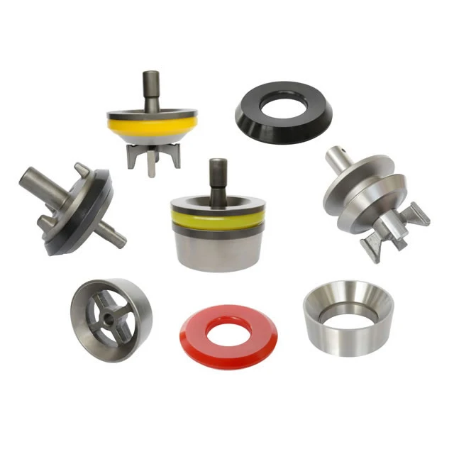
⊙Mud pump spare parts of abroad brand:Eg. Liner, piston, valve assembly, valve seat, valve spring, valve rubber could be alternative for original with lower price.
⊙Original brand:Emsco、Gardner-Denver, National oilwell, Ideco, Brewster, Drillmec, Wirth, Ellis, Williams, OPI, Mud King, LEWCO, Halliburton, SPM, Schlumberger, Weatherford.

Full-Open Valves . . . . . . . . . . . . . . . . . . . . . . . . . . . . . . . . . . . . . . . . . . . . . . . . . . . . . . . . . . . . . . . . . . . . . . 3
Mud-Pump Gear Sets . . . . . . . . . . . . . . . . . . . . . . . . . . . . . . . . . . . . . . . . . . . . . . . . . . . . . . . . . . . . . . . . . 13
Service and Support . . . . . . . . . . . . . . . . . . . . . . . . . . . . . . . . . . . . . . . . . . . . . . . . . . . . . . . . . . . . . . . . . . 16
Weatherford products and services are subject to the Company’s standard terms and conditions, available on request or at weatherford.com. For more information contact an authorized Weatherford representative. Unless noted
otherwise, trademarks and service marks herein are the property of Weatherford. Specifications are subject to change without notice. Weatherford sells its products and services in accordance with the terms and conditions set

Adjust or replace these bearings at first sign of wear. The bearings in the crank end are babbitt lined steel shells, adjustable for wear by removing shims and easily replaced when completely worn. These bearings should be watched closely and adjusted at first signs of looseness.. You will note on series 3400, 3800, 3500, and 3900 pumps, that the shims do not completely fill the outer gap between rod and cap casting, although the connecting rod bolts are tight. This is because the faces of the shell bearings project slightly beyond the faces of the rod and cap castings, and the shims are gripped only between the faces of the bearing halves. Do not try to close this outer gap by tightening the connecting rod bolt as it will put an excessive strain on the bolts.
To check for wear, place a wrench on the top connecting rod bolt and shake the rod parallel to the crankshaft. (The pressure must be relieved from the liquid end of the pump, so that the pump"s mechanism is free to move.) If the rod bearing moves without resistance, the bearing may be too loose and need adjusting. If the bearing does need adjusting, remove shims until you cannot shake the rod, then add .005" shims one at a time until there is little side movement. Be sure to torque rod bolt nuts to proper value for each adjustment. Oil clearance should be checked with Plastigage (available in most parts stores). Wipe crankshaft journal clean of any oil, place a strip of Plastigage on the crankshaft journal and tighten rod cap to the proper torque value. Once tightened, remove rod cap and measure oil clearance with scale on Plastigage package. See oil clearance chart. (NOTE: If you are making this adjustment after having had the crossheads out, be sure that the oil holes in the rod are pointing up. The "up" side is indicated by matching numbers stamped on the cap and rod at the split between them. These numbers should be the same on each rod and should be on the top side of the crankshaft.) Rotate the shaft by hand and if there is any hard drag or tight spots in the bearing, add another 0.005" shim. After this bearing is properly adjusted, loosen bolts a few turns and repeat the above operation on the other bearings. After all bearings have been adjusted.
Torque all connecting rod bolt nuts back to proper value. Again rotate the pump by hand to check for excessive drag and tight spots. If none, the pump should be ready for operation.
If the pump cannot be rotated by hand due to the drive being enclosed, care must-be taken: not to over-tighten the bearings, since they cannot be checked by rotating the pump. When bearings are adjusted by this method, watch carefully for overheating when the pump is put into operation.
It is usually better to have a bearing a little too loose than too tight. A slightly loose bearing will cause very little trouble because of the slow operating speeds of the pump, but a tight bearing will overheat and the babbitt may melt or pull. Normal precautions must be taken to insure cleanliness of parts upon their assembly.
Inspect connecting rod bearings and adjust as necessary every six months or when crankcase lubricant is changed. The bearings in the crank end are babbitt lined steel shells, adjustable for wear by removing shims and easily replaced when completely worn. These bearings should be watched closely and adjusted to compensate for wear. You will note that shims do not completely fill the outer gap between rod and cap casting although the connecting rod bolts are tight. This is because the faces of the shell bearings project slightly beyond the faces of the rod and cap castings and the shims are gripped only between the faces of the bearing halves. Do not try to close this outer gap by tightening the connecting rod bolt as it will put an excessive strain on them.
To check for wear, place a wrench on the top connecting rod bolt and shake the rod parallel to the crankshaft. (The pressure must be relieved from the liquid end of the pump so that the pump"s mechanism is free to move.) If the rod bearing moves without resistance, the bearing may be too loose and need adjusting. If the bearing does need adjusting, remove shims until you cannot shake the rod, then add .005" shims one at a time until there is a little side movement. Be sure to torque rod bolt nuts to proper value for each adjustment. (NOTE: If you are making this adjustment after having had the crossheads out, be sure that the oil holes in the rod are pointing up. The "up" side is indicated by matching numbers stamped on the cap and rod at the split between them. These numbers should be the same on each rod and should be on the top side of the crankshaft.) Turn the shaft by hand and if there is any hard drag or tight spots in the bearing, add another .005"" shim. After this bearing is properly adjusted, loosen bolts a few turns and repeat the above operation on the other bearings. After all bearings have been adjusted, torque all connecting rod bolt nuts back to proper amount. Again turn the pump by hand to check for excessive drag and tight spots. If none, the pump should then be ready for operation.
If the pump cannot be rotated by hand due to the drive being enclosed, the bearings may be completely adjusted by shaking the bearing on the shaft as stated above. Care must be taken not to over-tighten the bearings since they cannot be checked by rotating the pump by hand. When bearings are adjusted by this method, they must be watched carefully for overheating when the pump is put into operation.
Alternatively, plastic gauge strips, found in most parts stores may be used to adjust these bearings. It is usually better to have a bearing a little too loose than too tight. A slightly loose bearing will cause very little trouble because of the slow operating speeds of the pump, but a tight bearing will overheat and the babbitt may melt or pull. with experience, an operator can tell by feel when the bearings are properly adjusted. Normal precautions must be taken to insure cleanliness of parts upon their assembly. All wrenches used in adjusting these bearings are standard wrenches.


 8613371530291