
mud pump suction line strainer free sample
The design of pump suction / inlet piping defines the resulting hydraulic conditions experienced at the pump inlet / impeller. If the design fails to produce a uniform velocity distribution profile at the pump inlet many pump problems and failures can be traced. For example,
Any of these issues could lead to pump failure. Pump suction / inlet piping design includes the selection of reducer fitting type and minimum straight length requirement.
It’s standard practice to employ suction-side piping one or two sizes bigger than the pump inlet. A reducer fitting is typically used in pump suction piping to reduce the size of the suction pipe to match the size of the pump suction end flange. A reducer is a constriction and requires careful design to avoid both turbulence and the creation of pockets where air or vapour might collect. The best solution is to use an eccentric reducer orientated to eliminate the possibility of air pockets.
Because we want minimum frictional losses in pipe and full bore flow to the impeller eye. For the same flow rate, if we increase the line size, fluid velocity as well as frictional losses decreases. Greater the area of pipe, lower is the velocity, lower frictional loses (higher NPSHa), lower is differential pressure generated by the pump and there by lower power required by motor to drive the pump.
Suction pipe size smaller than the pump’s inlet size will increase the frictional losses that will further increase the power required by motor to drive the pump. Also the flow being reached at the pump inlet or impeller will not be of uniform velocity profile causing various issues discussed above.
The right pump suction pipe size is a compromise between cost (bigger pipes are more expensive) and excessive friction loss (small pipes cause high friction loss and will affect the pump performance).
Eccentric reducer is recommended for horizontal flow to the pump. This configuration prevents air pocket accumulation at the upstream end of the reducer. Concentric reducer is recommended for vertical inlet (suction) piping or horizontal installations where there is no potential for air vapor accumulation.
When the source of supply is above the pump, then the eccentric reducers must be placed with the flat side down. When the source of supply is below the pump, then the eccentric reducers must be placed with the flat side up.
Pumps, and especially centrifugal pumps, work most smoothly and efficiently when the fluid is delivered in a surge-free, smooth, laminar flow. Any form of turbulence reduces efficiency and increases wear and tear on the pump’s bearings, seals and other components.
ANSI/HI 9.8 American National Standard for Pump Intake Design (P21, 1998) states, “There shall be no flow disturbing fittings (such as partially open valves, tees, short radius elbows, etc.) closer than five suction pipe diameters from the pump. Fully open, non-flow disturbing valves, vaned elbows and reducers are not considered flow disturbing fittings.” This standard eliminates any reference to the possible flow distribution that could be generated by the reducer.
The concept is simple though, ensure stable and uniform flow onto the impeller eye. This results in fewer pump failures over the life of the pump due to vibration caused by flow induced turbulence.
In case several improperly specified parameters come into the equation (e.g. viscosity changes etc), then it would be prudent to install as many as ten suction pipe diameters of straight piping next to the reducer inlet flange. A number ranging between five (5) to ten (10) suction pipe diameters of straight pipe run is typically the recommended value in published technical literature.
Sometimes due to space constraints, it’s just not possible to make provision for a sufficient settling distance in the pipework before the pump. In these cases, use an inline flow conditioner or straightener.
Feed pipe must be fully submerged in the tank or vessel. If it’s too close to the surface of the fluid, the suction creates a vortex, drawing air (or other vapors) into the liquid and through the pumping system.
Feed pipe must not be too close to the bottom of the tank or vessel. If it’s too close to the bottom of fluid, the suction may draw up solids or sludge. This situation can be improved by use of strainer in pump suction piping. As a drawback strainers can create a large pressure drop and be responsible for cavitation and friction-loss.
All piping, valves and associated fittings should be independently supported, so as to place no strain on the pump housing. Also, forces and moments imposed on the pump nozzles do not exceed the allowable values specified by the vendor.
Pump shall be placed in such a manner that the suction nozzle elevation is always below the vessel or tank nozzle elevation and suction pipe shall be routed to prevent any pockets in the line.
As per OSID- 118 (Oil industries Safety Directorate stipulation) there shall be minimum 1 meter spacing between pumps e. g a minimum space of 1 meter must be provided in between the pumps and any potential obstructions (large block valves, steam turbine piping and tee type support from grade.)
What do you think about the above article – informative or needs improvements? What further details can be added about pump suction piping? Any question or query in your mind? Share your feedback and experience in the comment box below for making this article more interactive and meaningful.
Across any pumping system there is a complex pressure profile. This arises from many properties of the system: the throughput rate, head pressure, friction losses both inside the pump and across the system as a whole. In a centrifugal pump, for example, there is a large drop in pressure at the impeller and an increase again within its vanes (see diagram). In a positive displacement pump, the fluid’s pressure drops when it is drawn, essentially from rest, into the cylinder. The fluid’s pressure increases again when it is expelled.
If the pressure of the fluid at any point in the pump is lower than its vapour pressure, it will literally boil, forming vapour bubbles within the pump. The formation of bubbles leads to a loss in throughput and increased vibration and noise but the big danger is when the bubbles pass on into a section of the pump at higher pressure. The vapour condenses and the bubbles implode, releasing, locally, huge amounts of energy. This can be very damaging, causing severe erosion of the pump’s components.
To avoid cavitation, you need to match your pump to the fluid, system and application. This is a complex area and you are advised to discuss your application with the pump supplier.
To avoid cavitation, the pressure of the fluid must be maintained above its vapour pressure at all points as it passes through the pump. Manufacturers specify a property referred to as the Net Positive Suction Head Required or NPSH-R – this is their minimum recommended fluid inlet pressure, expressed in metres. The documentation supplied with your pump may contain charts showing how NPSH-R varies with flow.
In fact, NPSH-R is defined as the suction-side pressure at which cavitation reduces the discharge pressure by 3%. So, in designing the suction-side pipework for your system, you must ensure that it exceeds the manufacturer’s NPSH-R rating for the operating conditions. Your calculated value is termed the NPSH-Available (NPSH-A).
Remember, a manufacturer’s NPSH-R rating is the minimum recommended inlet head pressure: a pump is already experiencing cavitation at this pressure. Consequently, it is important to build in a safety margin of 0.5 to 1m to take account of this and other factors such as:
Pumps, and especially centrifugal pumps, work most efficiently when the fluid is delivered in a surge-free, smooth, laminar flow. Any form of turbulence reduces efficiency and increases wear and tear on the pump’s bearings, seals and other components.
There should be at least 5 pipe diameters’ worth of straight piping connecting to the pump. Never connect an elbow, reducer, valve, or strainer within this final run of pipework. If you connect an elbow directly to the pump flange, the fluid is effectively centrifuged towards the outer curve of the elbow and not directed into the centre (the eye) of the impeller. This creates stress on the pump’s bearings and seals which often leads to wear and premature failure.
Sometimes, it’s just not possible to make provision for a sufficient settling distance in the pipework before the pump. In these cases, use an inline flow conditioner or straightener.
It’s standard practice to employ suction-side piping one or two sizes bigger than the pump inlet - you should certainly never use any piping that is smaller than the pump’s inlet nozzle.
Small pipes result in larger friction losses, which means it costs more to run your pumping system. On the other hand, larger diameter pipes are more expensive – so you need to weigh up the increased cost with the likely energy saving resulting from reduced friction losses.
Larger pipework means that you’ll need a reducer before the pump inlet. A reducer is a constriction and requires careful design to avoid both turbulence and the creation of pockets where air or vapour might collect. The best solution is to use an eccentric reducer orientated to eliminate the possibility of air pockets.
As a general rule of thumb, suction pipe velocities should be kept below 2 m/s. At higher velocities, the greater friction causes noise, higher energy costs and increasing erosion, particularly if the fluid contains suspended solids. If your system contains any narrow pipes or other constrictions, bear in mind that the pipe velocity will be a lot higher at these points.
It’s best to keep air or vapour out of the pipework. Entrained gases cause a loss in pump performance, increase noise, vibration and component wear and tear. It’s therefore important to position the feed pipe correctly in the tank or vessel. It should be fully submerged. If it’s too close to the surface of the fluid, the suction creates a vortex, drawing air (or other vapours) into the liquid and through the pumping system. The feed pipe should also be clear of any other pipes, agitators or stirrer-paddles – anything that might drive air into the fluid. In shallow tanks or ponds, it may be advisable to use a baffle arrangement to protect the feed pipe from air entrainment.
You should also make sure that the feed pipe isn’t too close to the bottom of the tank or pond. If it is, the suction may draw up solids or sludge instead of air or vapour! The fluid may contain suspended solids in any case.
Some displacement pumps can cope with a mixed phase supply without any damage or major loss in performance. Centrifugal pumps are not so robust and must be protected from solids. In this situation you’ll need to install a filter or strainer. Filters can create a large pressure drop and be responsible for cavitation and friction-loss. The filter screen should have at least three times the free area of the pipe cross-section. Use a differential pressure gauge across the screen to look out for any increased pressure drop before clogging problems arise. This will also help in the accurate assessment of NPSH-A.
Obviously, pumps should be securely located - but so should the pipework. Don’t use one to support the other. All other components must be just as securely located and create no stresses or strains on any other parts of the system. Ensure that the pipe connecting to the pump’s inlet flange is aligned precisely with it. If you need to install non-return valves or flow control valves fit them on the discharge side of the pump, and never in suction-side pipework.
Ensure that conditions do not favour cavitation, particularly if you are using a centrifugal pump. This requires careful selection of the pump, its positioning and the head pressure.

System designers frequently place strainers on the suction side of a pump. This practice, ostensibly based on good intentions, is rarely a good idea and will create serious issues for the pump from the aspect of reduced and turbulent flow, inadequate net positive suction head available (NPSHa) and eventually blocked flow.
There are several acceptable methods and alternative designs to avoid these issues. There are also situations where placing the strainer on the suction side is the right thing to do, but it must be done correctly.
Normally the reasons for placing the strainer on the suction side of a pump seem like good ones, as it is prudent to protect the pump and the other ancillary components in the system.
This preventative design approach can work to preclude or mitigate fouling of heat exchangers, valve blockages and other component issues with small operating clearances and annulus voids, to name a few. In the case of some positive displacement pump types such as gear and screw pumps, it is imperative.
The first issue is that the strainer will inevitably clog. The clogging will reduce, and at some rate of closure, completely shut off flow to the pump suction, creating serious damage to the pump. The blockage also creates issues with the system and downstream components that rely on the flow provided by the pump. Example: another pump in series with the first pump.
The second issue is a marked reduction in NPSHa. The formula for NPSHa is shown below for reference. Every pump has a requirement for a given amount of suction energy that is referred to as net positive suction head required (NPSHr). The specific requirement is determined by the manufacturer and is published on their performance curves. The NPSHr data is determined by empirical means.
If you have read some of my previous articles, you already know that the suction side of the system must provide energy to deliver the liquid to the pump. The pump does not reach out and pull the fluid into the impeller. The pump does not suck the fluid into itself, as fluids do not have tensile strength. The suction system must provide a level of NPSHa. The level of NPSHa is either calculated or measured by the owner or operator of the system. It is imperative that there is more NPSHa than NPSHr. This difference is referred to as the margin. The Hydraulic Institute (HI) and American National Standards Institute (ANSI) have a published standard that covers this subject—ANSI/HI 9.6.1-2012.
The friction component of the NPSHa formula becomes increasingly large when the strainer becomes clogged. This is a negative component in the formula and as a result the reduction in available NPSH will cause the pump to cavitate.
If you look deeper into the cavitation phenomena, the reduction in flow caused by the restricted strainer will result in a higher velocity across the device. The fluid in the suction line must obey the law of conservation of energy, which states energy can neither be created nor destroyed, but it can be altered in form. This is best summarized in Bernoulli’s equation.
Bernoulli’s Law, simplified for this article, explains why the pressure will drop correspondingly as the velocity increases. The clogged strainer is why the velocity has increased in the first place. As the pressure drops, the vapor pressure will also be affected, and it is possible at some point for the liquid to change state and form a vapor. Centrifugal pumps are not capable of pumping air, vapor or non-condensable gases. If there is as little as 4 percent entrainment in the liquid, it can bind (vapor lock) the pump.
In oil and gas applications where the pump is upstream at the well head, there is simply no way to avoid the introduction of solid containments and dual phase fluids to the pump suction. It is extremely rare that a fluid coming out of the ground will be 100 percent gas free. A centrifugal pump cannot pump (compress) air or gas.
The comparative difference in the range of fluid densities is a factor of approximately 800. Different designs and sizes of pumps handle this issue in better ways than others, but at some level all centrifugal pumps will vapor lock and fail. The impeller eye will become blocked by the air, vapor or gas.
If the pump is a self-primer or simply a centrifugal pump placed in a lift condition application (externally primed), there can or will be performance issues should any restriction be placed in the suction line. Note that “lift” signifies that the level of the source liquid to be pumped is below the centerline of the pump impeller. The available NPSH will already be low because the static head component in the formula is now a negative quantity due to the lift condition. Further restrictions will add to the negative component of friction and for any temperature above ambient the vapor pressure component will also work against the pump.
If there are strainers on the suction side of the pump, the best step you can take is to add instrumentation and continuously monitor the differential pressure (DP) across the strainer. The strainer will have a resistance coefficient assigned by the manufacturer. This is a great place to use an automated alarm system. The DP across the strainer for both clean and dirty conditions should be known. There must be a low value of DP for the new and clean strainer; I prefer less than 2 pounds per square inch gauge (psig). Also, you can compare the low clean value of DP to a higher value for a clogged strainer as indication for action.
Note: You have to know the head loss across the strainer anyway to do the NPSHa calculation. How else would you know if there is sufficient margin in your design?
If the DP across the strainer is not automatically monitored and alarmed, then an operator must check on a scheduled basis. All changes must be recorded and action must be taken if the DP is out of specification. Even a difference of 1 or 2 psig DP can be the difference between success and failure.
Some of the better designs incorporate a duplex strainer arrangement so that one strainer can be offline for cleaning and maintenance with no disruption in service. Some designs automatically change over and clean with no operator action required.
The size of the suction pipe must have an adequate diameter to keep friction losses down and velocities in an acceptable range. I always recommend to keep liquid velocities on the suction side below 2 meters per second (6.6 feet per second) at the maximum, and one meter per second (3.3 feet per second) is better. Just as the suction pipe size must be adequate, so must the strainer size.
Strainers should be engineered and selected to keep the pressure drop down to an acceptable low and safe level. The industry rates strainers using “CV”—known as the flow coefficient. When selecting strainers, I suggest you work with a knowledgeable expert, because the selection process can be tricky for the uninitiated. Most strainer resistance coefficients are based on water and a given mesh size for the strainer screen. You may need to correct for viscosity and a different mesh depending on your fluid properties. You will also need to decide the capacity ratio known as open area ratio (OAR). The OAR will indicate how long you can operate the strainer before it will require cleaning or replacement.
In a good system design, the pump should be positioned close to the suction source, but there should also be at least 5 to 10 pipe diameters worth of straight, unobstructed piping connecting to the pump. Never connect any components such as an elbow, reducer, valve or strainer within the final run of pipework. A clogged strainer will present a turbulent flow profile to the pump suction. If you connect an elbow directly to the pump flange, the fluid will be forced toward the outside of the elbow and will not be directed into the center of the impeller. Most pumps are designed for fluid to be evenly loaded at the center of the impeller. Otherwise, the imbalance creates stress on the pump’s bearings and seals that leads to wear and premature failure.
It is noted and acknowledged that many processes are purposely designed to have strainers on the suction side of the pump. Some processes actually rely on the reduced pressure (vacuum) created in the process. An example would be a filter press. Note these systems and pumps are designed and instrumented for the additional stress.
Every rule usually has exceptions, but from the perspective of an industry best practice, I suggest thinking long and hard before the placement of strainers on the suction side of the pump—and you “exceptions” already know who you are.
Many pumps are designed to handle some amount and size of solids. The manufacturer can or will advise what size solids the pump will handle. It is typically a better idea to place the strainer on the discharge side of the pump if possible. If you must place the strainer on the suction side for a valid design reason, then take the proper steps to design the system to prevent pump issues caused by clogging.

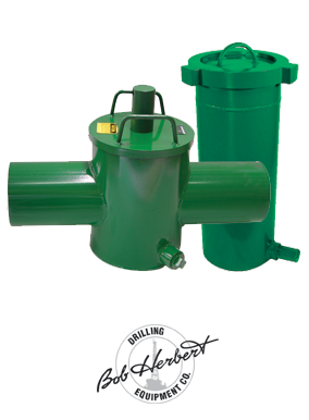
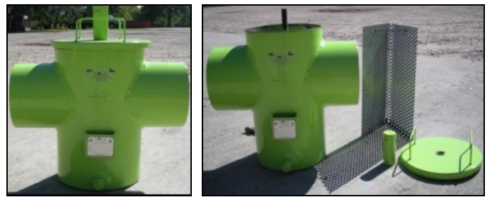
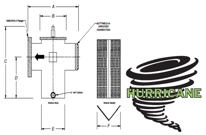
The HURRICANE suction line strainer protects mud pump fluid ends from unwanted debris entering the fluid stream. The strainer is easily cleaned and returned to service in minutes. A variety of end connections are available, including butt weld, flanged or threaded, to install in the suction line of any mud pump. HURRICANE strainers are built to withstand the rough service found on drilling rigs. Inlet / outlet diameters of 4”, 6”, 8”, 10” and 12” are standard. Provide the inlet / outlet size and height D as shown below with any price requests.

Discharge Head: This is the vertical distance that you are able to pump liquid. For example, if your pump is rated for a maximum head of 18 feet, this does not mean that you are restricted to 18 feet of pipe. You can use 300 feet, so long as the final discharge point is not higher than 18 feet above the liquid being pumped.
Suction Lift: This is the vertical distance that the pump can be above the liquid source. Typically, atmospheric pressure limits vertical suction lift of pumps to 25 feet at sea level. This does not mean that you are limited to 25 feet of pipe. You could use upwards of 300 feet of suction pipe, so long as the liquid source is not lower than 25 feet below the pump center line.
Suction line strainers are used to provide coarse filtering of the chemical being pumped, and to keep the end of the tubing weighted down to the bottom of the chemical tank.

Basket strainers are a device typically connected to a pumps suction, which is used to filter out solids or debris larger than the mesh contained within the strainer, which would otherwise damage the pump, internal parts or system. They are used to capture particles which are usually visible to the naked eye, and if smaller, filters are typically used.Strainer Vs Filter
Lower pressure drop enabling use of low pressure designs of pumpsRequire high pressure pumping involving high powered positive displacement or multistage pumps which if selected incorrectly will experience rapid wear by the handling of such particles
Designs consist of a suction inlet, discharge outlet, bolted top cover and casing. The casing holds a filter typically manufactured from wire mesh designed to filter solids which become trapped by the mesh, and sink within the casing. Top covers can be clear or solid. Housings may have a drain at the bottom of the casing where solids will sink to enable them to be drained away.
Duplex models are very similar to simplex strainers in design, however contain two filter baskets which can operate simultaneously or separately. Having twin filters ensures processes can run interrupted whilst they are maintained, as one can continue to function, while the other is maintained.
Within the strainer there is a hollow shaft with a blade which when the cleaning process is initiated, scrapes along the inside of the mesh removing debris. Simultaneously a bottom outlet valve opens creating an area of low pressure causing the recently freed debris to flow via the bottom outlet valve and be drained away.
During Cleaning as the strainer is at the lowest point, there is a larger loss of fluid and system may need to be drainedProcess must be stopped during cleaningBulkier in DesignLarge units requiring piping to drain, which may require secondary filtration or dewatering
Pressure Differential Indicator - This measures the pressure within the unit and when calibrated can detect high casing pressure, or higher inlet pressure signifying that the strainer mesh is blocked and requires cleaning.
Heating Jackets / Insulation Jackets – If material being filtered has a viscosity which changes with temperature then a heating jacket may be required to prevent solidification within the unit. Similarly, if strainers are subject to excessive heat from process such as within a steam process then an insulation jacket maybe required to ensure heat stress is not experienced by the unit unequally during operation.

It’s no secret that a pump that runs at peak efficiency uses less fuel, experiences less downtime and costs less to operate. The time you spend maintaining your pump is actually an investment in its lifetime performance and value. In fact, there are many ways that a diligently maintained pump can reduce your costs, while increasing efficiency. For instance, by ensuring your pump investment brings an ease-of-service design, the time you spend on maintenance can be significantly minimized.
Using the information below, see if you can identify some of your own trouble spots, and uncover potential solutions to get you back on the road to good pump health – boosting profits along the way.
Take notice of the discharge flow. Has it visibly decreased? Is it taking your pump longer to do the same job than it used to? The slowed flow may be caused by a collapsed suction hose lining, a leaking gasket, a plugged suction line or a damaged or worn impeller or wear plate.
To determine the cause of any decrease in flow, the discharge pressure and the suction vacuum should be measured while the pump is operating. If the pump discharge pressure and suction vacuum were measured at start up, the latest readings should be compared to the originally recorded readings. When troubleshooting any pump and system, follow the high abnormal reading taken earlier. A higher than normal discharge pressure reading will indicate a decrease in suction vacuum, and could be a sign of a clogged or partially clogged discharge line, a closed valve, air unable to evacuate or any obstruction outboard of the point the gauge was installed into the discharge line. It is common practice to install gauges approximately two to four pipe diameters from the pump.
Both gauges can also decrease. If they do, the problem is located between the installed locations of the gauges. In this case, the problem is within the pump. A clog at the eye of the impeller, wear, wide clearances and air induced into the suction line could all cause both gauge readings to decrease. Note that gauge readings almost always teeter back and forth. But again, follow the problem to the highest abnormal gauge reading.
The pump isn’t re-priming as rapidly as it once did. Most commonly, slower re-prime can be attributed to excessive face clearance. If this is not the cause of your slowdown, check the following:
A maximum vacuum check can be performed to determine the location of the problem. Fill the pump with the minimum amount of water than what the volute casing normally retains for re-priming. To do so, simply remove the suction flap valve, priming the volute casing and energizing the pump. After the pump achieves dynamic operation, turn the pump off and allow the liquid in the pump to return to the sump.
Whatever product remains in the volute casing is the minimum left for a re-prime cycle. Install a vacuum gauge on the suction side of the pump and close a valve in the suction line outboard of the gauge. If there are no valves in the suction line, a solid gasket without an inside diameter hole may be installed in a pipe joint to create a “valve” effect. Energize the pump and inspect the vacuum gauge. The pump will pull a vacuum against the closed valve or solid gasket. This reading is the equivalent to the pump’s lift capabilities. If a vacuum gauge calibrated in inches of mercury (Hg) is used, multiply that reading by 1.13 to convert to feet of water.
If your pump sounds like a bunch of marbles rattling in a can, this may be an indication of cavitation – and could be caused by a suction lift that’s too high, a suction hose that’s too long, plugged or has a collapsed lining, a clogged strainer, a combination of any of these, or perhaps a problem on the discharge side of the pump. Failing bearings can also cause excessive noise. Noise should be qualified as mechanical or hydraulic noise. Run the pump briefly without water. If the noise is no longer present, the noise is one of a hydraulic nature. If the noise is present after removing the product, the noise is mechanical. Again, a quality set of gauge readings will direct your attention to the problem side of the system if the noise is deemed to be a hydraulic noise.
If a pump’s suction check valve is clogged, the strainer may be too large or too small, or face clearance could be too wide. Alternatively, the strainer may be stuck in mud, plugging the suction side.
In this case, very likely, the flow of liquid into or out of the pump is being restricted. Improper impeller clearance could be slowing re-priming, the suction strainer or recirculation port in the volute casing may be clogged or the pump’s ability to handle air through an air release line, air release valve or open ended discharge line may be obstructed. Never open a hot pump. Allow the pump to cool to the touch prior to opening. Even after cooling, there may be lingering pressure inside the volute casing.
Using a vacuum gauge, make sure that the suction line, fittings and pipe plugs are airtight. Pumps, such as Gorman-Rupp pumps typically have a tapped hole for easy connection of a vacuum gauge. Use pipe dope to seal gauge threads and pipe plugs. A vacuum gauge will fluctuate or give erratic readings while handling air during operation. At shut down, the suction gauge reading will display the vertical distance from the gauge tap to the product level. If this vacuum falls off after shut down, atmospheric pressure is entering the suction pipe causing the pump to lose its static lift. Replace the suction flap valve if worn and check for air leaks if the product returns to the sump. Replace leaky seals and badly worn hoses, if necessary.
The rubber lining in a suction hose can pull away from the fabric, causing partial blockage of the line. If the pump develops a high vacuum but low discharge pressure, the hose lining may be blocking suction flow. Gauge readings during operation will be higher than normal with the lining collapsed. To rectify this problem, simply replace the hose. Check the suction strainer. Frequent inspection and cleaning of the suction strainer is particularly important when pumping liquids containing solids. Gauge readings during operation will be higher than normal if debris obstructs the flow through the strainer. Always use the proper size strainer to prevent the pump from clogging.
Check the volute casing, impeller vanes, wear plate or wear rings and attaching hardware. A removable cover plate on the pump allows for quick, easy access when inspection of the impeller and wear plate is needed. These components should be inspected every six months or sooner, depending on pump application because they are subject to faster wear when pumping abrasive liquids and slurries. Gorman-Rupp wear plates and wear rings, for instance, can be replaced without replacing expensive castings. A shut off test can be performed to measure the internal wear. Start the pump and allow it to achieve full flow. Slowly close a discharge valve and record suction and discharge gauge readings. Those reading should equal the maximum pressure noted on the pump performance curve at zero flow.
Pumping efficiency will be reduced if the clearance between impeller and wear plate or wear rings is beyond the recommended limits. If the clearance is less than recommended, components will wear by rubbing, causing excess work for the engine or motor. Check the impeller clearance against the pump manual specifications and adjust it if necessary. A shut off test can be performed to verify not only wear but face clearance as well.
Better pumps are equipped with a double seal, which is lubricated under pressure by a spring-loaded grease cup, or an oil-lubricated seal for long, trouble-free service. Some pumps are equipped with a single seal that is lubricated by the liquid being pumped. Sand or other solids can cause rapid wear of the seal faces. Check and replace the seal if worn. The maximum vacuum test will qualify the integrity of the pump’s seal. Replace the seal liner or shaft sleeve if they have scratches.
Worn bearings can cause the shaft to wobble. Eventually the pump will become noisy and overheat. Worn bearings will reflect higher amperage readings due to the increased wear. Sooner or later it will freeze up and stop. Replace bearings at the first sign of wear to alleviate destructive damaged caused when bearings fail catastrophically.
The pump may not be getting the power it needs to operate efficiently. The engine may need a tune-up, or the motor may need service. Refer to the owner’s manual often for optimum efficiency.
Check air release devices, valves, check valves and shock control devices for proper operation. Old discharge lines are subject to internal rusting and pitting, which cause friction loss and reduce flow by as much as 15%. A discharge gauge reading will increase with the additional losses. Replace badly deteriorated lines.
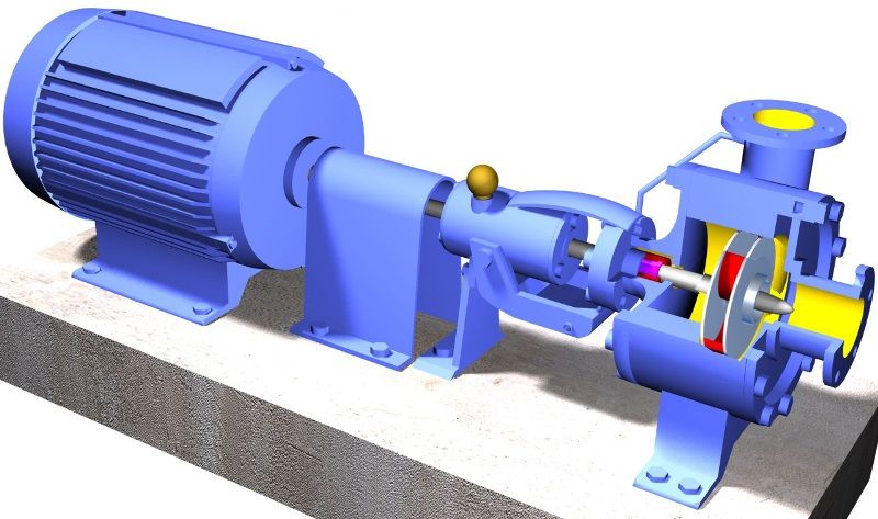
Centrifugal pumps basically consist of a stationary pump casing and an impeller mounted on a rotating shaft. The pump casing provides a pressure boundary for the pump and contains channels to properly direct the suction and discharge flow. The pump casing has suction and discharge penetrations for the main flow path of the pump and normally has small drain and vent fittings to remove gases trapped in the pump casing or to drain the pump casing for maintenance.
Some centrifugal pumps contain diffusers. A diffuser is a set of stationary vanes that surround the impeller. The purpose of the diffuser is to increase the efficiency of the centrifugal pump by allowing a more gradual expansion and less turbulent area for the liquid to reduce in velocity. The diffuser vanes are designed in a manner that the liquid exiting the impeller will encounter an everincreasing flow area as it passes through the diffuser. This increase in flow area causes a reduction in flow velocity, converting kinetic energy into flow pressure.
Impellers of pumps are classified based on the number of points that the liquid can enter the impeller and also on the amount of webbing between the impeller blades.
Impellers can be either single-suction or double-suction. A single-suction impeller allows liquid to enter the center of the blades from only one direction. A double-suction impeller allows liquid to enter the center of the impeller blades from both sides simultaneously. Figure 4 shows simplified diagrams of single and double-suction impellers.
The impeller sometimes contains balancing holes that connect the space around the hub to the suction side of the impeller. The balancing holes have a total cross-sectional area that is considerably greater than the cross-sectional area of the annular space between the wearing ring and the hub. The result is suction pressure on both sides of the impeller hub, which maintains a hydraulic balance of axial thrust.
Centrifugal pumps can be classified based on the manner in which fluid flows through the pump. The manner in which fluid flows through the pump is determined by the design of the pump casing and the impeller. The three types of flow through a centrifugal pump are radial flow, axial flow, and mixed flow.
A centrifugal pump with a single impeller that can develop a differential pressure of more than 150 psid between the suction and the discharge is difficult and costly to design and construct. A more economical approach to developing high pressures with a single centrifugal pump is to include multiple impellers on a common shaft within the same pump casing. Internal channels in the pump casing route the discharge of one impeller to the suction of another impeller. Figure 9 shows a diagram of the arrangement of the impellers of a four-stage pump. The water enters the pump from the top left and passes through each of the four impellers in series, going from left to right. The water goes from the volute surrounding the discharge of one impeller to the suction of the next impeller.
Centrifugal pumps vary in design and construction from simple pumps with relatively few parts to extremely complicated pumps with hundreds of individual parts. Some of the most common components found in centrifugal pumps are wearing rings, stuffing boxes, packing, and lantern rings. These components are shown in Figure 10 and described on the following pages.
Some wear or erosion will occur at the point where the impeller and the pump casing nearly come into contact. This wear is due to the erosion caused by liquid leaking through this tight clearance and other causes. As wear occurs, the clearances become larger and the rate of leakage increases. Eventually, the leakage could become unacceptably large and maintenance would be required on the pump.
To minimize the cost of pump maintenance, many centrifugal pumps are designed with wearing rings. Wearing rings are replaceable rings that are attached to the impeller and/or the pump casing to allow a small running clearance between the impeller and the pump casing without causing wear of the actual impeller or pump casing material. These wearing rings are designed to be replaced periodically during the life of a pump and prevent the more costly replacement of the impeller or the casing.
In almost all centrifugal pumps, the rotating shaft that drives the impeller penetrates the pressure boundary of the pump casing. It is important that the pump is designed properly to control the amount of liquid that leaks along the shaft at the point that the shaft penetrates the pump casing. There are many different methods of sealing the shaft penetration of the pump casing. Factors considered when choosing a method include the pressure and temperature of the fluid being pumped, the size of the pump, and the chemical and physical characteristics of the fluid being pumped.
One of the simplest types of shaft seal is the stuffing box. The stuffing box is a cylindrical space in the pump casing surrounding the shaft. Rings of packing material are placed in this space. Packing is material in the form of rings or strands that is placed in the stuffing box to form a seal to control the rate of leakage along the shaft. The packing rings are held in place by a gland. The gland is, in turn, held in place by studs with adjusting nuts. As the adjusting nuts are tightened, they move the gland in and compress the packing. This axial compression causes the packing to expand radially, forming a tight seal between the rotating shaft and the inside wall of the stuffing box.
The high speed rotation of the shaft generates a significant amount of heat as it rubs against the packing rings. If no lubrication and cooling are provided to the packing, the temperature of the packing increases to the point where damage occurs to the packing, the pump shaft, and possibly nearby pump bearings. Stuffing boxes are normally designed to allow a small amount of controlled leakage along the shaft to provide lubrication and cooling to the packing. The leakage rate can be adjusted by tightening and loosening the packing gland.
It is not always possible to use a standard stuffing box to seal the shaft of a centrifugal pump. The pump suction may be under a vacuum so that outward leakage is impossible or the fluid may be too hot to provide adequate cooling of the packing. These conditions require a modification to the standard stuffing box.
One method of adequately cooling the packing under these conditions is to include a lantern ring. A lantern ring is a perforated hollow ring located near the center of the packing box that receives relatively cool, clean liquid from either the discharge of the pump or from an external source and distributes the liquid uniformly around the shaft to provide lubrication and cooling. The fluid entering the lantern ring can cool the shaft and packing, lubricate the packing, or seal the joint between the shaft and packing against leakage of air into the pump in the event the pump suction pressure is less than that of the atmosphere.
In some situations, packing material is not adequate for sealing the shaft. One common alternative method for sealing the shaft is with mechanical seals. Mechanical seals consist of two basic parts, a rotating element attached to the pump shaft and a stationary element attached to the pump casing. Each of these elements has a highly polished sealing surface. The polished faces of the rotating and stationary elements come into contact with each other to form a seal that prevents leakage along the shaft.
A diffuser increases the efficiency of a centrifugal pump by allowing a more gradual expansion and less turbulent area for the liquid to slow as the flow area expands.
Wearing rings are replaceable rings that are attached to the impeller and/or the pump casing to allow a small running clearance between the impeller and pump casing without causing wear of the actual impeller or pump casing material.
Many centrifugal pumps are designed in a manner that allows the pump to operate continuously for months or even years. These centrifugal pumps often rely on the liquid that they are pumping to provide cooling and lubrication to the pump bearings and other internal components of the pump. If flow through the pump is stopped while the pump is still operating, the pump will no longer be adequately cooled and the pump can quickly become damaged. Pump damage can also result from pumping a liquid whose temperature is close to saturated conditions.
The flow area at the eye of the pump impeller is usually smaller than either the flow area of the pump suction piping or the flow area through the impeller vanes. When the liquid being pumped enters the eye of a centrifugal pump, the decrease in flow area results in an increase in flow velocity accompanied by a decrease in pressure. The greater the pump flow rate, the greater the pressure drop between the pump suction and the eye of the impeller. If the pressure drop is large enough, or if the temperature is high enough, the pressure drop may be sufficient to cause the liquid to flash to vapor when the local pressure falls below the saturation pressure for the fluid being pumped. Any vapor bubbles formed by the pressure drop at the eye of the impeller are swept along the impeller vanes by the flow of the fluid. When the bubbles enter a region where local pressure is greater than saturation pressure farther out the impeller vane, the vapor bubbles abruptly collapse. This process of the formation and subsequent collapse of vapor bubbles in a pump is called cavitation.
Cavitation in a centrifugal pump has a significant effect on pump performance. Cavitation degrades the performance of a pump, resulting in a fluctuating flow rate and discharge pressure. Cavitation can also be destructive to pumps internal components. When a pump cavitates, vapor bubbles form in the low pressure region directly behind the rotating impeller vanes. These vapor bubbles then move toward the oncoming impeller vane, where they collapse and cause a physical shock to the leading edge of the impeller vane. This physical shock creates small pits on the leading edge of the impeller vane. Each individual pit is microscopic in size, but the cumulative effect of millions of these pits formed over a period of hours or days can literally destroy a pump impeller. Cavitation can also cause excessive pump vibration, which could damage pump bearings, wearing rings, and seals.
A small number of centrifugal pumps are designed to operate under conditions where cavitation is unavoidable. These pumps must be specially designed and maintained to withstand the small amount of cavitation that occurs during their operation. Most centrifugal pumps are not designed to withstand sustained cavitation.
Noise is one of the indications that a centrifugal pump is cavitating. A cavitating pump can sound like a can of marbles being shaken. Other indications that can be observed from a remote operating station are fluctuating discharge pressure, flow rate, and pump motor current. Methods to stop or prevent cavitation are presented in the following paragraphs.
To avoid cavitation in centrifugal pumps, the pressure of the fluid at all points within the pump must remain above saturation pressure. The quantity used to determine if the pressure of the liquid being pumped is adequate to avoid cavitation is the net positive suction head (NPSH). The net positive suction head available (NPSHA) is the difference between the pressure at the suction of the pump and the saturation pressure for the liquid being pumped. The net positive suction head required (NPSHR) is the minimum net positive suction head necessary to avoid cavitation.
The condition that must exist to avoid cavitation is that the net positive suction head available must be greater than or equal to the net positive suction head required. This requirement can be stated mathematically as shown below.
When a centrifugal pump is taking suction from a tank or other reservoir, the pressure at the suction of the pump is the sum of the absolute pressure at the surface of the liquid in the tank plus the pressure due to the elevation difference between the surface of liquid in the tank and the pump suction less the head losses due to friction in the suction line from the tank to the pump.
If a centrifugal pump is cavitating, several changes in the system design or operation may be necessary to increase the NPSHA above the NPSHR and stop the cavitation. One method for increasing the NPSHA is to increase the pressure at the suction of the pump. For example, if a pump is taking suction from an enclosed tank, either raising the level of the liquid in the tank or increasing the pressure in the space above the liquid increases suction pressure.
It is also possible to increase the NPSHA by decreasing the temperature of the liquid being pumped. Decreasing the temperature of the liquid decreases the saturation pressure, causing NPSHA to increase. Recall from the previous module on heat exchangers that large steam condensers usually subcool the condensate to less than the saturation temperature, called condensate depression, to prevent cavitation in the condensate pumps.
If the head losses in the pump suction piping can be reduced, the NPSHA will be increased. Various methods for reducing head losses include increasing the pipe diameter, reducing the number of elbows, valves, and fittings in the pipe, and decreasing the length of the pipe.
It may also be possible to stop cavitation by reducing the NPSHR for the pump. The NPSHR is not a constant for a given pump under all conditions, but depends on certain factors. Typically, the NPSHR of a pump increases significantly as flow rate through the pump increases. Therefore, reducing the flow rate through a pump by throttling a discharge valve decreases NPSHR. NPSHR is also dependent upon pump speed. The faster the impeller of a pump rotates, the greater the NPSHR. Therefore, if the speed of a variable speed centrifugal pump is reduced, the NPSHR of the pump decreases. However, since a pump’s flow rate is most often dictated by the needs of the system on which it is connected, only limited adjustments can be made without starting additional parallel pumps, if available.
The net positive suction head required to prevent cavitation is determined through testing by the pump manufacturer and depends upon factors including type of impeller inlet, impeller design, pump flow rate, impeller rotational speed, and the type of liquid being pumped. The manufacturer typically supplies curves of NPSHR as a function of pump flow rate for a particular liquid (usually water) in the vendor manual for the pump.
For a given centrifugal pump operating at a constant speed, the flow rate through the pump is Figure 11 Centrifugal Pump Characteristic Curve dependent upon the differential pressure or head developed by the pump. The lower the pump head, the higher the flow rate. A vendor manual for a specific pump usually contains a curve of pump flow rate versus pump head called a pump characteristic curve. After a pump is installed in a system, it is usually tested to ensure that the flow rate and head of the pump are within the required specifications. A typical centrifugal pump characteristic curve is shown in Figure 11.
A centrifugal pump is dead-headed when it is operated with no flow through it, for example, with a closed discharge valve or against a seated check valve. If the discharge valve is closed and there is no other flow path available to the pump, the impeller will churn the same volume of water as it rotates in the pump casing. This will increase the temperature of the liquid (due to friction) in the pump casing to the point that it will flash to vapor. The vapor can interrupt the cooling flow to the pump’s packing and bearings, causing excessive wear and heat. If the pump is run in this condition for a significant amount of time, it will become damaged.
When a centrifugal pump is installed in a system such that it may be subjected to periodic shutoff head conditions, it is necessary to provide some means of pump protection. One method for protecting the pump from running dead-headed is to provide a recirculation line from the pump discharge line upstream of the discharge valve, back to the pump’s supply source. The recirculation line should be sized to allow enough flow through the pump to prevent overheating and damage to the pump. Protection may also be accomplished by use of an automatic flow control device.
Centrifugal pumps must also be protected from runout. Runout can lead to cavitation and can also cause overheating of the pump’s motor due to excessive currents. One method for ensuring that there is always adequate flow resistance at the pump discharge to prevent excessive flow through the pump is to place an orifice or a throttle valve immediately downstream of the pump discharge. Properly designed piping systems are very important to protect from runout.
Gas binding of a centrifugal pump is a condition where the pump casing is filled with gases or vapors to the point where the impeller is no longer able to contact enough fluid to function correctly. The impeller spins in the gas bubble, but is unable to force liquid through the pump. This can lead to cooling problems for the pump’s packing and bearings.
Centrifugal pumps are designed so that their pump casings are completely filled with liquid during pump operation. Most centrifugal pumps can still operate when a small amount of gas accumulates in the pump casing, but pumps in systems containing dissolved gases that are not designed to be self-venting should be periodically vented manually to ensure that gases do not build up in the pump casing.
Most centrifugal pumps are not self-priming. In other words, the pump casing must be filled with liquid before the pump is started, or the pump will not be able to function. If the pump casing becomes filled with vapors or gases, the pump impeller becomes gas-bound and incapable of pumping. To ensure that a centrifugal pump remains primed and does not become gas-bound, most centrifugal pumps are located below the level of the source from which the pump is to take its suction. The same effect can be gained by supplying liquid to the pump suction under pressure supplied by another pump placed in the suction line.
Damage to pump impeller, bearings, wearing rings, and sealsTo avoid pump cavitation, the net positive suction head available must be greater than the net positive suction head required.
Gas binding of a centrifugal pump is a condition where the pump casing is filled with gases or vapors to the point where the impeller is no longer able to contact enough fluid to function correctly.
Centrifugal pumps are protected from runout by placing an orifice or throttle valve immediately downstream of the pump discharge and through proper piping system design.
A positive displacement pump is one in which a definite volume of liquid is delivered for each cycle of pump operation. This volume is constant regardless of the resistance to flow offered by the system the pump is in, provided the capacity of the power unit driving the pump or pump component strength limits are not exceeded. The positive displacement pump delivers liquid in separate volumes with no delivery in between, although a pump having several chambers may have an overlapping delivery among individual chambers, which minimizes this effect. The positive displacement pump differs from centrifugal pumps, which deliver a continuous flow for any given pump speed and discharge resistance.
Positive displacement pumps can be grouped into three basic categories based on their design and operation. The three groups are reciprocating pumps, rotary pumps, and diaphragm pumps.
During the suction stroke, the piston moves to the left, causing the check valve in the suction Figure 12 Reciprocating Positive Displacement Pump Operation line between the reservoir and the pump cylinder to open and admit water from the reservoir. During the discharge stroke, the piston moves to the right, seating the check valve in the suction line and opening the check valve in the discharge line. The volume of liquid moved by the pump in one cycle (one suction stroke and one discharge stroke) is equal to the change in the liquid volume of the cylinder as the piston moves from its farthest left position to its farthest right position.
Reciprocating positive displacement pumps are generally categorized in four ways: direct-acting or indirect-acting; simplex or duplex; single-acting or double-acting; and power pumps.
Some reciprocating pumps are powered by prime movers that also have reciprocating motion, such as a reciprocating pump powered by a reciprocating steam piston. The piston rod of the steam piston may be directly connected to the liquid piston of the pump or it may be indirectly connected with a beam or linkage. Direct-acting pumps have a plunger on the liquid (pump) end that is directly driven by the pump rod (also the piston rod or extension thereof) and carries the piston of the power end. Indirect-acting pumps are driven by means of a beam or linkage connected to and actuated by the power piston rod of a separate reciprocating engine.
A simplex pump, sometimes referred to as a single pump, is a pump having a single liquid (pump) cylinder. A duplex pump is the equivalent of two simplex pumps placed side by side on the same foundation.
The driving of the pistons of a duplex pump is arranged in such a manner that when one piston is on its upstroke the other piston is on its downstroke, and vice versa. This arrangement doubles the capacity of the duplex pump compared to a simplex pump of comparable design.
A single-acting pump is one that takes a suction, filling the pump cylinder on the stroke in only one direction, called the suction stroke, and then forces the liquid out of the cylinder on the return stroke, called the discharge stroke. A double-acting pump is one that, as it fills one end of the liquid cylinder, is discharging liquid from the other end of the cylinder. On the return stroke, the end of the cylinder just emptied is filled, and the end just filled is emptied. One possible arrangement for single-acting and double-acting pumps is shown in Figure 13.
Power pumps typically have high efficiency and are capable of developing very high pressures. Figure 13 Single-Acting and Double-Acting Pumps They can be driven by either electric motors or turbines. They are relatively expensive pumps and can rarely be justified on the basis of efficiency over centrifugal pumps. However, they are frequently justified over steam reciprocating pumps where continuous duty service is needed due to the high steam requirements of direct-acting steam pumps.
In general, the effective flow rate of reciprocating pumps decreases as the viscosity of the fluid being pumped increases because the speed of the pump must be reduced. In contrast to centrifugal pumps, the differential pressure generated by reciprocating pumps is independent of fluid density. It is dependent entirely on the amount of force exerted on the piston. For more information on viscosity, density, and positive displacement pump theory, refer to the handbook on Thermodynamics, Heat Transfer, and Fluid Flow.
Rotary pumps operate on the principle that a rotating vane, screw, or gear traps the liquid in the suction side of the pump casing and forces it to the discharge side of the casing. These pumps are essentially self-priming due to their capability of removing air from suction lines and producing a high suction lift. In pumps designed for systems requiring high suction lift and selfpriming features, it is essential that all clearances between rotating parts, and between rotating and stationary parts, be kept to a minimum in order to reduce slippage. Slippage is leakage of fluid from the discharge of the pump back to its suction.
Due to the close clearances in rotary pumps, it is necessary to operate these pumps at relatively low speed in order to secure reliable operation and maintain pump capacity over an extended period of time. Otherwise, the erosive action due to the high velocities of the liquid passing through the narrow clearance spaces would soon cause excessive wear and increased clearances, resulting in slippage.
There are many types of positive displacement rotary pumps, and they are normally grouped into three basic categories that include gear pumps, screw pumps, and moving vane pumps.
There are several variations of gear pumps. The simple gear pump shown in Figure 14 consists of two spur gears meshing together and revolving in opposite directions within a casing. Only a few thousandths of an inch clearance exists between the case and the gear faces and teeth extremities. Any liquid that fills the space bounded by two successive gear teeth and the case must follow along with the teeth as they revolve. When the gear teeth mesh with the teeth of the other gear, the space between the teeth is reduced, and the entrapped liquid is forced out the pump discharge pipe. As the gears revolve and the teeth disengage, the space again opens on the suction side of the pump, trapping new quantities of liquid and carrying it around the pump case to the discharge. As liquid is carried away from the suction side, a lower pressure is created, which draws liquid in through the suction line.
With the large number of teeth usually employed on the gears, the discharge is relatively smooth and continuous, with small quantities of liquid being delivered to the discharge line in rapid succession. If designed with fewer teeth, the space between the teeth is greater and the capacity increases for a given speed; however, the tendency toward a pulsating discharge increases. In all simple gear pumps, power is applied to the shaft of one of the gears, which transmits power to the driven gear through their meshing teeth.
There are no valves in the gear pump to cause friction losses as in the reciprocating pump. The high impeller velocities, with resultant friction losses, are not required as in the centrifugal pump. Therefore, the gear pump is well suited for handling viscous fluids such as fuel and lubricating oils.
There are two types of gears used in gear pumps in addition to the simple spur gear. One type is the helical gear. A helix is the curve produced when a straight line moves up or down the surface of a cylinder. The other type is the herringbone gear. A herringbone gear is composed of two helixes spiraling in different directions from the center of the gear. Spur, helical, and herringbone gears are shown in Figure 15.
The helical gear pump has advantages over the simple spur gear. In a spur gear, the entire length of the gear tooth engages at the same time. In a helical gear, the point of engagement moves along the length of the gear tooth as the gear rotates. This makes the helical gear operate with a steadier discharge pressure and fewer pulsations than a spur gear pump.
The herringbone gear pump is also a modification of the simple gear pump. Its principal difference in operation from the simple spur gear pump is that the pointed center section of the space between two teeth begins discharging before the divergent outer ends of the preceding space complete discharging. This overlapping tends to provide a steadier discharge pressure. The power transmission from the driving to the driven gear is also smoother and quieter.
The lobe type pump shown in Figure 16 is another variation of the simple gear pump. It is considered as a simple gear pump having only two or three teeth per rotor; otherwise, its operation or the explanation of the function of its parts is no different. Some designs of lobe pumps are fitted with replaceable gibs, that is, thin plates carried in grooves at the extremity of each lobe where they make contact with the casing. The gib promotes tightness and absorbs radial wear.
There are many variations in the design of the screw type positive displacement, rotary pump. The primary differences consist of the number of intermeshing screws involved, the pitch of the screws, and the general direction of fluid flow. Two common designs are the two-screw, low-pitch, double-flow pump and the three-screw, high-pitch, double-flow pump.
The complete assembly and the usual flow Figure 18 Three-Screw, High-Pitch, Screw Pump path are shown in Figure 17. Liquid is trapped at the outer end of each pair of screws. As the first space between the screw threads rotates away from the opposite screw, a one-turn, spiral-shaped quantity of liquid is enclosed when the end of the screw again meshes with the opposite screw. As the screw continues to rotate, the entrapped spiral turns of liquid slide along the cylinder toward the center discha


 8613371530291