
mud pump that gives sufficient flowrate but not enough pressure brands

When choosing a size and type of mud pump for your drilling project, there are several factors to consider. These would include not only cost and size of pump that best fits your drilling rig, but also the diameter, depth and hole conditions you are drilling through. I know that this sounds like a lot to consider, but if you are set up the right way before the job starts, you will thank me later.
Recommended practice is to maintain a minimum of 100 to 150 feet per minute of uphole velocity for drill cuttings. Larger diameter wells for irrigation, agriculture or municipalities may violate this rule, because it may not be economically feasible to pump this much mud for the job. Uphole velocity is determined by the flow rate of the mud system, diameter of the borehole and the diameter of the drill pipe. There are many tools, including handbooks, rule of thumb, slide rule calculators and now apps on your handheld device, to calculate velocity. It is always good to remember the time it takes to get the cuttings off the bottom of the well. If you are drilling at 200 feet, then a 100-foot-per-minute velocity means that it would take two minutes to get the cuttings out of the hole. This is always a good reminder of what you are drilling through and how long ago it was that you drilled it. Ground conditions and rock formations are ever changing as you go deeper. Wouldn’t it be nice if they all remained the same?
Centrifugal-style mud pumps are very popular in our industry due to their size and weight, as well as flow rate capacity for an affordable price. There are many models and brands out there, and most of them are very good value. How does a centrifugal mud pump work? The rotation of the impeller accelerates the fluid into the volute or diffuser chamber. The added energy from the acceleration increases the velocity and pressure of the fluid. These pumps are known to be very inefficient. This means that it takes more energy to increase the flow and pressure of the fluid when compared to a piston-style pump. However, you have a significant advantage in flow rates from a centrifugal pump versus a piston pump. If you are drilling deeper wells with heavier cuttings, you will be forced at some point to use a piston-style mud pump. They have much higher efficiencies in transferring the input energy into flow and pressure, therefore resulting in much higher pressure capabilities.
Piston-style mud pumps utilize a piston or plunger that travels back and forth in a chamber known as a cylinder. These pumps are also called “positive displacement” pumps because they literally push the fluid forward. This fluid builds up pressure and forces a spring-loaded valve to open and allow the fluid to escape into the discharge piping of the pump and then down the borehole. Since the expansion process is much smaller (almost insignificant) compared to a centrifugal pump, there is much lower energy loss. Plunger-style pumps can develop upwards of 15,000 psi for well treatments and hydraulic fracturing. Centrifugal pumps, in comparison, usually operate below 300 psi. If you are comparing most drilling pumps, centrifugal pumps operate from 60 to 125 psi and piston pumps operate around 150 to 300 psi. There are many exceptions and special applications for drilling, but these numbers should cover 80 percent of all equipment operating out there.
The restriction of putting a piston-style mud pump onto drilling rigs has always been the physical size and weight to provide adequate flow and pressure to your drilling fluid. Because of this, the industry needed a new solution to this age-old issue.
Enter Cory Miller of Centerline Manufacturing, who I recently recommended for recognition by the National Ground Water Association (NGWA) for significant contributions to the industry.
As the senior design engineer for Ingersoll-Rand’s Deephole Drilling Business Unit, I had the distinct pleasure of working with him and incorporating his Centerline Mud Pump into our drilling rig platforms.
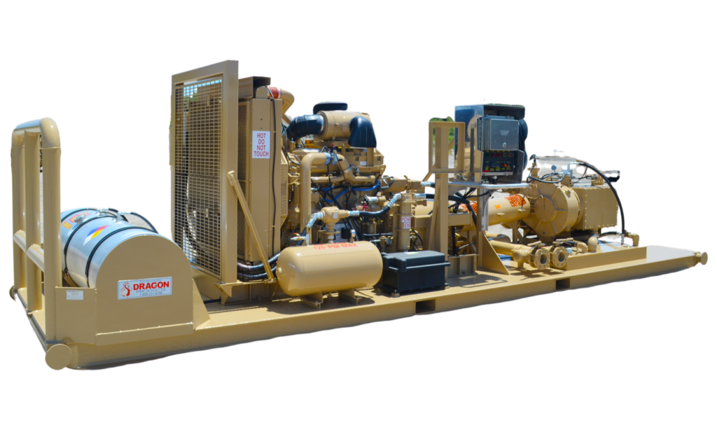
In the late ’90s — and perhaps even earlier — Ingersoll-Rand had tried several times to develop a hydraulic-driven mud pump that would last an acceptable life- and duty-cycle for a well drilling contractor. With all of our resources and design wisdom, we were unable to solve this problem. Not only did Miller provide a solution, thus saving the size and weight of a typical gear-driven mud pump, he also provided a new offering — a mono-cylinder mud pump. This double-acting piston pump provided as much mud flow and pressure as a standard 5 X 6 duplex pump with incredible size and weight savings.
The true innovation was providing the well driller a solution for their mud pump requirements that was the right size and weight to integrate into both existing and new drilling rigs. Regardless of drill rig manufacturer and hydraulic system design, Centerline has provided a mud pump integration on hundreds of customer’s drilling rigs. Both mono-cylinder and duplex-cylinder pumps can fit nicely on the deck, across the frame or even be configured for under-deck mounting. This would not be possible with conventional mud pump designs.
Centerline stuck with their original design through all of the typical trials and tribulations that come with a new product integration. Over the course of the first several years, Miller found out that even the best of the highest quality hydraulic cylinders, valves and seals were not truly what they were represented to be. He then set off on an endeavor to bring everything in-house and began manufacturing all of his own components, including hydraulic valves. This gave him complete control over the quality of components that go into the finished product.
The second generation design for the Centerline Mud Pump is expected later this year, and I believe it will be a true game changer for this industry. It also will open up the application to many other industries that require a heavier-duty cycle for a piston pump application.

AfghanistanAlbaniaAlgeriaAmerican SamoaAndorraAngolaAnguillaAntarcticaAntigua and BarbudaArgentinaArmeniaArubaAustraliaAustriaAzerbaijanBahamasBahrainBangladeshBarbadosBelarusBelgiumBelizeBeninBermudaBhutanBoliviaBonaire, Sint Eustatius and SabaBosnia and HerzegovinaBotswanaBouvet IslandBrazilBritish Indian Ocean TerritoryBrunei DarussalamBulgariaBurkina FasoBurundiCabo VerdeCambodiaCameroonCanadaCayman IslandsCentral African RepublicChadChileChinaChristmas IslandCocos IslandsColombiaComorosCongoCongo, Democratic Republic of theCook IslandsCosta RicaCroatiaCubaCuraçaoCyprusCzechiaCôte d"IvoireDenmarkDjiboutiDominicaDominican RepublicEcuadorEgyptEl SalvadorEquatorial GuineaEritreaEstoniaEswatiniEthiopiaFalkland IslandsFaroe IslandsFijiFinlandFranceFrench GuianaFrench PolynesiaFrench Southern TerritoriesGabonGambiaGeorgiaGermanyGhanaGibraltarGreeceGreenlandGrenadaGuadeloupeGuamGuatemalaGuernseyGuineaGuinea-BissauGuyanaHaitiHeard Island and McDonald IslandsHoly SeeHondurasHong KongHungaryIcelandIndiaIndonesiaIranIraqIrelandIsle of ManIsraelItalyJamaicaJapanJerseyJordanKazakhstanKenyaKiribatiKorea, Democratic People"s Republic ofKorea, Republic ofKuwaitKyrgyzstanLao People"s Democratic RepublicLatviaLebanonLesothoLiberiaLibyaLiechtensteinLithuaniaLuxembourgMacaoMadagascarMalawiMalaysiaMaldivesMaliMaltaMarshall IslandsMartiniqueMauritaniaMauritiusMayotteMexicoMicronesiaMoldovaMonacoMongoliaMontenegroMontserratMoroccoMozambiqueMyanmarNamibiaNauruNepalNetherlandsNew CaledoniaNew ZealandNicaraguaNigerNigeriaNiueNorfolk IslandNorth MacedoniaNorthern Mariana IslandsNorwayOmanPakistanPalauPalestine, State ofPanamaPapua New GuineaParaguayPeruPhilippinesPitcairnPolandPortugalPuerto RicoQatarRomaniaRussian FederationRwandaRéunionSaint BarthélemySaint Helena, Ascension and Tristan da CunhaSaint Kitts and NevisSaint LuciaSaint MartinSaint Pierre and MiquelonSaint Vincent and the GrenadinesSamoaSan MarinoSao Tome and PrincipeSaudi ArabiaSenegalSerbiaSeychellesSierra LeoneSingaporeSint MaartenSlovakiaSloveniaSolomon IslandsSomaliaSouth AfricaSouth Georgia and the South Sandwich IslandsSouth SudanSpainSri LankaSudanSurinameSvalbard and Jan MayenSwedenSwitzerlandSyria Arab RepublicTaiwanTajikistanTanzania, the United Republic ofThailandTimor-LesteTogoTokelauTongaTrinidad and TobagoTunisiaTurkmenistanTurks and Caicos IslandsTuvaluTürkiyeUS Minor Outlying IslandsUgandaUkraineUnited Arab EmiratesUnited KingdomUnited StatesUruguayUzbekistanVanuatuVenezuelaViet NamVirgin Islands, BritishVirgin Islands, U.S.Wallis and FutunaWestern SaharaYemenZambiaZimbabweÅland Islands
This website is using a security service to protect itself from online attacks. The action you just performed triggered the security solution. There are several actions that could trigger this block including submitting a certain word or phrase, a SQL command or malformed data.

The 2,200-hp mud pump for offshore applications is a single-acting reciprocating triplex mud pump designed for high fluid flow rates, even at low operating speeds, and with a long stroke design. These features reduce the number of load reversals in critical components and increase the life of fluid end parts.
The pump’s critical components are strategically placed to make maintenance and inspection far easier and safer. The two-piece, quick-release piston rod lets you remove the piston without disturbing the liner, minimizing downtime when you’re replacing fluid parts.

I’ve run into several instances of insufficient suction stabilization on rigs where a “standpipe” is installed off the suction manifold. The thought behind this design was to create a gas-over-fluid column for the reciprocating pump and eliminate cavitation.
When the standpipe is installed on the suction manifold’s deadhead side, there’s little opportunity to get fluid into all the cylinders to prevent cavitation. Also, the reciprocating pump and charge pump are not isolated.
Another benefit of installing a suction stabilizer is eliminating the negative energies in fluids caused by the water hammer effect from valves quickly closing and opening.
The suction stabilizer’s compressible feature is designed to absorb the negative energies and promote smooth fluid flow. As a result, pump isolation is achieved between the charge pump and the reciprocating pump.
The isolation eliminates pump chatter, and because the reciprocating pump’s negative energies never reach the charge pump, the pump’s expendable life is extended.
Investing in suction stabilizers will ensure your pumps operate consistently and efficiently. They can also prevent most challenges related to pressure surges or pulsations in the most difficult piping environments.
Sigma Drilling Technologies’ Charge Free Suction Stabilizer is recommended for installation. If rigs have gas-charged cartridges installed in the suction stabilizers on the rig, another suggested upgrade is the Charge Free Conversion Kits.

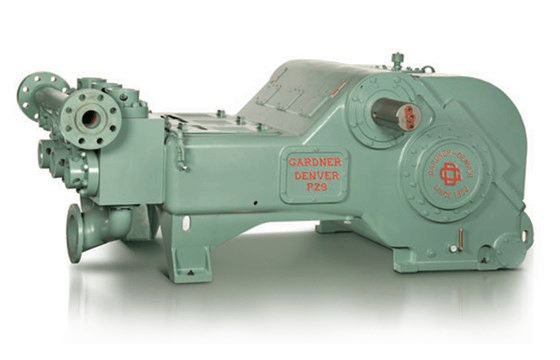
A mud pump (sometimes referred to as a mud drilling pump or drilling mud pump), is a reciprocating piston/plunger pump designed to circulate drilling fluid under high pressure (up to 7,500 psi or 52,000 kPa) down the drill string and back up the annulus. A mud pump is an important part of the equipment used for oil well drilling and manufactured according to API specification 7K.
The advantages of the drilling mud pump include the ability to move high-solids-content fluids laden with abrasives, the ability to pump large particles, ease of operation and maintenance, reliability, and the ability to operate over a wide range of pressures and flow rates by changing the diameter of pump liners and pistons.
As an important equipment for oilfield drilling operation, a drilling mud pump delivers circulating high-pressure drilling fluid or drilling mud to the bottom of the oil well, flushes the bottom of the well, breaks the rock, cools, lubricates and clean the drill bit, and carries the cuttings back to the ground.
The drilling mud is also used to suspend and carry out drill cuttings from the drill bits as it is brought in and out of the hole. This ensures that the drill bit does not clog and overheat, and makes the entire drilling operation smooth and safe.
Rotational power is supplied to the mud pump through an external power source like a diesel engine or electric motor. The power end of the mud pump converts the rotational energy through a crankshaft to a reciprocating motion of pistons.
The pistons move back and forth in mud pump liners, exerting a force on the cylinder chamber. During the retraction of the piston, valves open to allow the fluid to be drawn into the cylinder. Once the piston has fully retracted, it is pushed back into the cylinder.
At this time the intake valves are closed and the exhaust valves open, allowing the piston to force the fluid out of the cylinder under pressure. Once the piston reaches its maximum depth into the cylinder, the exhaust valves close and the process repeats.
Your water pump is primed and the liquid is flowing… kind of. One of the more common problems with water pumps is a reduced or lower than expected water flow. When you need to dewater the jobsite, low flow means more downtime for the crew, costing money and putting deadlines at risk. Often, low water flow is less about your water pump and more to do with the situation. Below are a few things to review to troubleshoot water pump problems involving low water flow.
The greater the distance a pump has to pull the water, the lower the flow rate will be. Get too far from the water source and the more power is dedicated to ‘sucking’ the water and less to discharging, reducing the flow rate.
Typically, pumps should be with 20 feet of the water source. Depending on the typography, how high the pump is relative to the water, the flow may be reduced at even shorter distances. Your pump has individual specification, so be sure you read the spec and operate within them.
Your pump is designed to operate with a certain diameter input line. In some cases, we have seen people attach a smaller than recommended hose or line (using a reduction couplings). Depending on the intake line you use, it is also possible that the line crimps, or is “sucked in” on itself.
Debri blockage is a common problem. With murky water it can be hard to see the intake hose. But, operators should check to be sure there is no debris blocking the intake. The blockage usually happens at the filter as it does it’s job to prevent damage to the water pump. Remove the debri and reposition the hose to start pumping again.
The intake filter or screen can also be the culprit even without debri . While you must ensure the filter is fine enough to prevent damaging solids from entering the pump, too fine a filter for the water pump will restrict the flow right as the water enters the intake. Be sure the filter is proper for the pump.
Centrifugal water pumps are designed to operate with the impeller going in one direction. If it is going the opposite direction, the pump will not operate properly. This can happen if the electrical connections to the electric motor is not established correctly. Review the electric motors setup and user instructions to ensure your connections are correct.
Whether you are dewatering a jobsite, irrigating a field or applying your water pump for any other purpose, low flow is an issue. In some cases, like a firefighting pump, it can be a matter of life-or-death. One way to minimize onsite issue it to check all your equipment on a regular basis, replacing worn parts and performing maintenance as needed. But when confronted with low flow rates, follow the above steps and you’ll be able to get your water pump back in action, and your crew back to work.
Industrial pumps are essential devices required in every phase of oil and gas operations. Basically, they help transfer process fluids from one point to another.
For example, a pump can be used to transfer crude oil from a storage tank to a pipeline and mud pumps are used to circulate drilling mud into the annulus of a drill bit and back to a storage tank for re-purification.
In oil and gas operations, process fluids can range from easy to difficult. Depending on the nature of the substance you want to transfer and your required flow rate, you’ll need a suitable pump for your needs.
Various types of industrial pumps are utilized for fluid transfer in the oil and gas industry. Pumps used in O&G can be classified based on their design and construction and generally fall into 6 major categories:
Centrifugal pumps are the most common types of pumps used in the oil and gas industry. Centrifugal pumps use centrifugal force through the rotation of the pump impeller to draw fluid into the intake of the pump and force it through the discharge section via centrifugal force. The flow through the pump is controlled by discharge flow control valves.
Single stage centrifugal pumps are primarily used for transferring low-viscosity fluids that require high flow rates. They are typically used as part of a larger pump network comprising other centrifugal pumps like horizontal multistage pump units for crude oil shipping or water injection pumps used in secondary oil and gas recovery.
Plunger pumps are some of the most ubiquitous industrial pumps in the oil and gas industry. Plunger pumps use the reciprocating motion of plungers and pistons to pressurize fluid in an enclosed cylinder to a piping system. Plunger pumps are considered constant flow pumps since at a given speed, the flow rate is constant despite the system pressure. A relief valve is an essential part of any plunger pump discharge piping system to prevent overpressuring of the pump and piping system.
Plunger pumps require more frequent maintenance than centrifugal pumps due to the design of the moving parts. They also have a noisier operation than centrifugal pumps.
A progressive cavity pump is a type of positive displacement pump and is also known as an eccentric screw pump or cavity pump. It transfers fluid by means of the progress, through the pump, of a sequence of small, fixed shape, discrete cavities, as its rotor is turned. Progressive cavity pumps are used in high viscosity applications or if blending the of the pumped fluid is not desired.
Progressive cavity pumps are also considered constant flow pumps since at a given speed, the flow rate is relatively constant despite the system pressure. Flow slippage is normal at higher pressures. A relief valve is an essential part of any progressive cavity pump discharge piping system to prevent overpressuring of the pump and piping system.
Diaphragm pumps are one of the most versatile types of oil and gas pumps in the industry and transfer fluid through positive displacement with a valve and diaphragm. The working principle of this pump is that a decrease in volume causes an increase in pressure in a vacuum and vice versa.
Diaphragm pumps are suitable for high-volume fluid transfer operations in oil refineries. They also require much less maintenance than positive displacement pumps due to their fewer moving parts and less friction during operation and are available in compact designs.
On the downside, diaphragm pumps are susceptible to ‘winks’ – low-pressure conditions inside the system that slow down pumping operations. Fortunately, winks can be rectified by using a back-pressure regulator. For the same reason, they are not suitable for continuous or long-distance pumping operations as they generally don’t meet the high-pressure conditions required.
A gear pump uses the meshing of gears to pump fluid by displacement. Gear pumps are one of the most common types of positive displacement pumps for transferring industrial fluids.
Gear pumps are also widely used for chemical transfer applications for high viscosity fluids. There are two main variations: external gear pumps which use two external spur gears or timing gears that drive the internal gear set. The internal gears do not touch, so non-lubricating fluids can be pumped with external gear pumps. Internal gear pumps use a shaft driven drive gear to drive the internal mating gear. Gear pumps are positive displacement (or fixed displacement), meaning they pump a constant amount of fluid for each revolution.
Since the pumped fluid passes between the close gear tolerances, gear pumps are normally used for clean fluids. A relief valve is an essential component in the discharge piping system to protect the pump and piping from over pressurizing.
A metering pump moves a precise volume of liquid in a specified time period providing an accurate flow rate. Delivery of fluids in precise adjustable flow rates is sometimes called metering. The term “metering pump” is based on the application or use rather than the exact kind of pump used. Most metering pumps are simplex reciprocating pumps with a packed plunger or diaphragm liquid end. The diaphragm liquid end is preferred since the pumped fluid is sealed inside the diaphragm. No pumped liquid leaks to the atmosphere.

Deep-well turbine pumps are adapted for use in cased wells or where the water surface is below the practical limits of a centrifugal pump. Turbine pumps also are used with surface water systems.
Because the intake for the turbine pump is continuously under water, priming is not a concern. Turbine pump efficiencies are comparable to or greater than most centrifugal pumps. They usually are more expensive than centrifugal pumps and more difficult to inspect and repair.
The turbine pump has three main parts: head assembly, shaft and column assembly and pump bowl assembly, as shown in Figure 4. The head normally is cast iron and designed to be installed on a foundation. It supports the column, shaft and bowl assemblies and provides a discharge for the water. It also will support an electric motor, a right-angle gear drive or a belt drive.
The shaft and column assembly provides a connection between the head and pump bowls. The line shaft transfers the power from the motor to the impellers, and the column carries the water to the surface. The line shaft on a turbine pump may be water- or oil-lubricated.
The oil-lubricated pump has a hollow shaft into which oil drips, lubricating the bearings. The water-lubricated pump has an open shaft. The bearings are lubricated by the pumped water. If pumping fine sand is a possibility, select the oil-lubricated pump because it will keep the sand out of the bearings.
If the water is for domestic or livestock use, it must be free of oil, and a water-lubricated pump must be used. In some states, such as Minnesota, you have no choice; water-lubricated pumps are required in all new irrigation wells.
Line shaft bearings commonly are placed on 10-foot centers for water- lubricated pumps operating at speeds under 2,200 RPM and at 5-foot centers for pumps operating at higher speeds. Oil-lubricated bearings commonly are placed on 5-foot centers.
A pump bowl encloses the impeller. Due to its limited diameter, each impeller develops a relatively low head. In most deep-well turbine installations, several bowls are stacked in series one above the other. This is called staging. A four-stage bowl assembly contains four impellers all attached to a common shaft and will operate at four times the discharge head of a single-stage pump.
Impellers used in turbine pumps may be semi-open or enclosed, as shown in Figure 5. The vanes on semi-open impellers are open on the bottom and they rotate with a close tolerance to the bottom of the pump bowl.
The tolerance is critical and must be adjusted when the pump is new. During the initial break-in period, the line shaft couplings will tighten; therefore, after about 100 hours of operation, the impeller adjustments should be checked. After break-in, the tolerance must be checked and adjusted every three to five years or more often if pumping sand.
Both types of impellers may cause inefficient pump operation if they are not adjusted properly. Mechanical damage will result if the semi-open impellers are set too low and the vanes rub against the bottom of the bowls. The adjustment of enclosed impellers is not as critical; however, they still must be checked and adjusted.
Impeller adjustments are made by tightening or loosening a nut on the top of the head assembly. Impeller adjustments normally are made by lowering the impellers to the bottom of the bowls and adjusting them upward. The amount of upward adjustment is determined by how much the line shaft will stretch during pumping. The adjustment must be made based on the lowest possible pumping level in the well.
The pump manufacturer often provides the proper adjustment procedure. The adjustment procedure for many of the common deep-well turbine brands is outlined in Nebraska Cooperative Extension Service publication EC 81-760, titled “How to adjust vertical turbine pumps for maximum efficiency.”

Agustinus K, Zein JM, Irawan F, Wuest C (2016) Managed pressure drilling application to deploy lower completion safely and efficiently in static-underbalanced well. In: Offshore technology conference Asia, Kuala Lumpur, Malaysia, 22–25 March 2016. https://doi.org/10.4043/26713-ms
Ahmed MA, Hegab OA, Sabry A (2015) Early detection enhancement of the kick and near-balance drilling using mud logging warning sign. Egypt J Basic Appl Sci 3:85–93. https://doi.org/10.1016/j.ejbas.2015.09.006
Alkamil EHK, Abbood HR (2018) Using managed pressure drilling to reduce stuck pipe problem. In: SPE Kingdom of Saudi Arabia annual technical symposium and exhibition, Dammam, Saudi Arabia, 23–26 April 2018
Almetayev R, Al Hosani M, Al Ameri S, Al Mutawa A, Hussain MA (2018) First nitrified managed pressure drilling application in United Arab Emirates. In: Abu Dhabi international petroleum exhibition & conference, Abu Dhabi, UAE, 12–15 November 2018
Bacon W, Sugden C, Brand P, Gabaldon O, Culen M (2016) MPD dynamic influx control mitigates conventional well control pitfalls. In: SPE/IADC managed pressure drilling and underbalanced operations conference and exhibition, Galveston, Texas, USA. https://doi.org/10.2118/179185-ms
Bacon W, Tong A, Gabaldon O, Sugden C, Suryanarayana PV (2012) An improved dynamic well control response to a gas influx in managed pressure drilling operations. In: SPE/IADC drilling conference, San Diego, California, USA. https://doi.org/10.2118/151392-ms
Bassam A, Del Castillo AÁ, García-Valladares O, Santoyo E (2015) Determination of pressure drops in flowing geothermal wells by using artificial neural networks and wellbore simulation tools. Appl Therm Eng 75:1217–1228. https://doi.org/10.1016/j.applthermaleng.2014.05.048
Blue, D., Blakey, T., Rowe, M., 2019. Advanced mud logging: Key to safe and efficient well delivery, in: Annual Offshore Technology Conference. Houston, Texas, USA, 6 – 9 May 2019, pp. 6–9. https://doi.org/10.4043/29469-ms
Borges S, Dobrokhleb P, Krivolapov D, Magda A, Soroka T, Moiseenko I (2018) Successful application of different managed pressure drilling techniques in Russia: identification of challenges and selection of the optimum approach. In: SPE annual Caspian technical conference and exhibition, Astana, Kazakhstan, 31st October–2nd November 2018. https://doi.org/10.2118/192533-MS
Breyholtz Ø, Nygaard G, Nikolaou M (2010) Automatic control of managed pressure drilling. In: American control conference, Baltimore, MD, USA. https://doi.org/10.1109/acc.2010.5531008
Carlsen LA, Nygaard G, Gravdal JE, Nikolaou M, Schubert J (2008) Performing the dynamic shut-in procedure because of a kick incident when using automatic coordinated control of pump rates and choke-valve opening. In: Society of petroleum engineers—SPE/IADC managed pressure drilling and underbalanced operations conference and exhibition 2008, pp 116–128. https://doi.org/10.2118/113693-ms
Cenberlitas SA, Crenshaw JE, Gumus F, International W, Alpaugh K (2011) MPD technique in Haynesville shale delivers significant value in over pressured zones. In: AADE-11-NTCE-55
Choe J, Schubert JJ, Juvkam-Wold HC (2007) Analyses and procedures for kick detection in subsea mudlift drilling. SPE Drill Complet 22:296–303. https://doi.org/10.2118/87114-pa
Culen MS, Brand PR, Bacon W, Gabaldon OR (2016) Evolution of the MPD operations matrix: the influx management envelope. In: SPE/IADC managed pressure drilling and underbalanced operations conference and exhibition, Galveston, Texas, USA. https://doi.org/10.2118/179191-ms
Davoudi M, Smith JR, Patel BM, Chirinos JE (2011) Evaluation of alternative initial responses to kicks taken during managed-pressure drilling. SPE Drill Complet 26:169–181. https://doi.org/10.2118/128424-PA
Dow B, Rojas F, Hobin J, Rojas J, Gallo F, Abuelaish A, Swaco M (2020) Managed pressure drilling—an unconventional efficiency tool applied in deepwater. In: Offshore technology conference, Houston, TX, USA, 4–7 May 2020
Driedger DJ, Kelly SP, Leggett C, Thain J, Silva M (2013) Managed pressure drilling technique applied in a Kurdistan exploration well. In: SPE Middle East oil and gas show and conference, Manama, Bahrain. https://doi.org/10.2118/164403-ms
Eaton AN, Beal LDR, Thorpe SD, Janis EH, Hubbell C, Hedengren JD, Nybø R, Aghito M, Bjørkevoll K, El Boubsi R, Braaksma J, Van Og G (2015) Ensemble model Predictive control for robust automated managed pressure drilling. In: Proceedings—SPE annual technical conference and exhibition, Houston, Texas, USA. https://doi.org/10.2118/174969-ms
Egbe P, Iturrios C (2020) Mitigating drilling hazards in a high differential pressure well using managed pressure drilling and cementing techniques. In: International petroleum technology conference, Dhahran, Saudi Arabia, 13–15 January 2020. https://doi.org/10.2523/iptc-20180-ms
Erge O, Ozbayoglu EM, Miska SZ, Yu M, Takach N, Saasen A, May R (2015) The effects of drillstring-eccentricity, -rotation, and -buckling configurations on annular frictional pressure losses while circulating yield-power-law fluids. In: SPE drilling and completion, Fort Worth, Texas, USA. https://doi.org/10.2118/167950-PA
Feng J, Fu J, Chen P, Liu Z, Wei H (2015) Predicting pressure behavior during dynamic kill drilling with a two-phase flow. J Nat Gas Sci Eng 22:591–597. https://doi.org/10.1016/j.jngse.2015.01.006
Fredericks P, Reitsma D, Runggai T, Hudson N, Zaeper R, Backhaus O, Hernandez M (2008) Successful implementation of first closed loop, multiservice control system for automated pressure management in a shallow gas well offshore Myanmar. In: SPE/IADC drilling conference, Orlando, Florida, USA. https://doi.org/10.2118/112651-ms
Fu J, Su Y, Jiang W, Xu L (2015) Development and testing of kick detection system at mud line in deepwater drilling. J Pet Sci Eng 135:452–460. https://doi.org/10.1016/j.petrol.2015.10.013
Gedge B, Kaur H, Singh D, Refugio E, Quoc BT, Pacific WA, Minh HC (2013) Managed pressure drilling—a solution for drilling the challenging and un-drillable wells in Vietnam and South East Asia. In: SPE Asia Pacific oil & gas conference and exhibition, Jakarta, Indonesia
Godhavn JM (2010) Control requirements for automatic managed pressure drilling system. SPE Drill Complet 25:336–345. https://doi.org/10.2118/119442-PA
Gravdal JE, Lorentzen RJ, Fjelde KK, Vefring EH (2005) Tuning of computer model parameters in managed-pressure drilling applications using an unscented Kalman filter technique. In: Proceedings—SPE annual technical conference and exhibition, pp 4007–4015. https://doi.org/10.2523/97028-ms
Gravdal JE, Nikolaou M, Breyholtz Ø, Carlsen LA (2010) Improved kick management during MPD by real-time pore-pressure estimation. SPE Drill Complet 25:577–584. https://doi.org/10.2118/124054-PA
Grayson B (2009) Increased operational safety and efficiency with managed pressure drilling. In: SPE Americas E and P environmental and safety conference, San Antonio, Texas. https://doi.org/10.2118/120982-ms
Guner H (2009) Simulation study of emerging well control methods for influxes caused by bottomhole pressure fluctuations during managed pressure drilling table of contents. Lousiana State University, Baton Rouge
Guo W, Honghai F, Gang L (2011) Design and calculation of a MPD model with constant bottom hole pressure. Pet Explor Dev 38:103–108. https://doi.org/10.1016/S1876-3804(11)60017-7
Hannegan DM (2011) Managed pressure drilling applications on offshore HPHT wells. In: Offshore technology conference, Houston, Texas, USA, 2–5 May. https://doi.org/10.4043/21208-ms
He M, Liu G, Li J, Li J, Zhang T, Liu W, Li M (2015) Study of sour gas kicks taken during managed pressure drilling operations. In: SPE/IATMI Asia Pacific oil and gas conference and exhibition, Nusa Dua, Bali, Indonesia. https://doi.org/10.2118/176337-ms
Hernandez J, Arnone M, Valecillos J, Vives J, Vannoort R, Groves D, Hawthorn A (2019) Using managed pressure drilling and early kick/loss detection system to execute a challenging deepwater completions job in the Gulf of Mexico. In: IADC/SPE managed pressure drilling and underbalanced operations conference and exhibition 2019, Amsterdam, The Netherlands, 09–10 April 2019. https://doi.org/10.2118/194554-ms
Hoberock LL, Stanbery SR (1981) Pressure dynamics in wells during gas kicks-2. Component models and results. JPT J Pet Technol 33:1367–1378. https://doi.org/10.2118/9822-pa
Hovland S, van Kuilenburg R, Drilling N, Eide T, Stridsklev C, Munro C (2019) Lessons learned with real integration of a deepwater MPD control system. In: IADC/SPE managed pressure drilling and underbalanced operations conference and exhibition, Amsterdam, The Netherlands, 09–10 April 2019. https://doi.org/10.2118/194543-ms
Jiang H, Liu G, Li J, Zhang T, Wang C (2020) Drilling fault classification based on pressure and flowrate responses via ensemble classifier in managed pressure drilling. J Pet Sci Eng 190:107126. https://doi.org/10.1016/j.petrol.2020.107126
Johnson A, Piccolo B, Pinkstone H, Anderson B, Fraczek J (2017) Augmenting deepwater well control with managed pressure drilling equipment. In: SPE/IATMI Asia Pacific oil and gas conference and exhibition. https://doi.org/10.2118/186331-ms
Karimi Vajargah A, van Oort E (2015) Early kick detection and well control decision-making for managed pressure drilling automation. J Nat Gas Sci Eng 27:354–366. https://doi.org/10.1016/j.jngse.2015.08.067
Kinik K, Gumus F, Osayande N (2015) Automated dynamic well control with managed-pressure drilling: a case study and simulation analysis. SPE Drill Complet 30:110–118. https://doi.org/10.2118/168948-PA
Kinik K, Gumus F, Osayande N (2014) A case study: first field application of fully automated kick detection and control by MPD system in western Canada. In: SPE/IADC managed pressure drilling and underbalanced operations conference and exhibition, Madrid, Spain
Lordejani SN, Abbasi MH, Velmurugan N, Paristech M (2020) Modeling and numerical implementation of managed-pressure-drilling systems for the assessment of pressure-control systems. SPE Drill Complet. 1–22. https://doi-org.qe2a-proxy.mun.ca/10.2118/201108-PA
Mahdianfar H, Pavlov A, Aamo OM (2013) Joint unscented Kalman filter for state and parameter estimation in managed pressure drilling. 2013 European control conference, ECC 2013, pp 1645–1650. https://doi.org/10.23919/ecc.2013.6669753
Mathew S, Nasr GG (2012) Optimized drilling by improved well control using MPD in narrow pressure window. In: SPE international production and operations conference and exhibition, Doha Qatar, 14–16 May 2012
MMS (2008) Notice to lessees and operators of federal oil, gas and sulphur leases in the outer continental shelf, Gulf of Mexico OCS region: managed pressure drilling projects
Moosavinia M, Parker M, Alexandrov V, Palenov M (2016) Intelligent control for MPD. In: SPE/IADC managed pressure drilling and underbalanced operations conference and exhibition, Galveston, Texas, USA. https://doi.org/10.2118/180069-ms
Nabiyev A, Nauduri S, Parker M, Fisher D, Cunningham D (2019) MPD called to a post well-control event to free a differentially stuck pipe. In: IADC/SPE managed pressure drilling and underbalanced operations conference and exhibition, Amsterdam, The Netherlands, 09–10 April 2019
Nandan A, Imtiaz S (2016) Nonlinear model predictive controller for kick attenuation in managed pressure drilling. IFAC-PapersOnLine 49:248–253. https://doi.org/10.1016/j.ifacol.2016.07.268
Nandan A, Imtiaz S, Butt S (2015) Robust control of managed pressure drilling. In: 2014 Ocean.—St. John’s, Ocean 2014, pp 1–8. https://doi.org/10.1109/OCEANS.2014.7003172
Nandan A, Imtiaz S, Butt S (2014) Control of bottomhole pressure in managed pressure drilling using IMC controller. In: Society of petroleum engineers—Arctic technology conference 2014, pp 584–590. https://doi.org/10.4043/24614-ms
Nas S (2011) Kick detection and well control in a closed wellbore. In: Society of petroleum engineers—IADC/SPE managed pressure drilling and underbalanced operations conference and exhibition, pp 93–102. https://doi.org/10.1071/aj10006
Nas S, Toralde JS, Wuest C (2009) Offshore managed pressure drilling experiences in Asia Pacific. In: SPE/IADC drilling conference, Amsterdam, The Netherlands, pp 1099–1111. https://doi.org/10.2118/119875-ms
Onifade J, Patel B, Ertas E, Sammat E, Sahin B, Petroleum T (2015) Managed pressure drilling system provided value to offshore drilling variants of MPD technology. In: SPE/IADC managed pressure drilling and underbalanced operations conference and exhibition, Dubai, UAE
Pontes, T., Barbosa, F., Cosendey, S., 2018. Managed pressure drilling in deepwater Brazil presalt severe-loss scenario, in: SPE/IADC Managed Pressure Drilling and Underbalanced Operations Conference and Exhibition. New Orleans, Louisiana, USA, 17–18 April 2018. https://doi.org/10.2118/189998-ms
Prairie G, Malik HK, Litwin RJ, Jones BC, Canada CCOP (2010) Successful use of managed pressure drilling (MPD) to counteract loss circulation and HP gas zones: a case study from red rock South Wapiti. In: Canadian unconventional resources & international petroleum conference, Calgary, Alberta, Canada, 19–21 October 2010
Qutob H, Vieira P, Torres F, Arnone M (2011) Managed pressure drilling applications proves successful in the Middle East and North Africa Region. In: SPE/IADC Middle East drilling technology conference and exhibition, Muscat, Oman, pp 649–660. https://doi.org/10.2118/148534-ms
Reitsma D (2010) A simplified and highly effective method to identify influx and losses during managed pressure drilling without the use of a Coriolis flow meter. In: SPE/IADC managed pressure drilling and underbalanced operations conference and exhibition 2010, Kuala Lumpur, Malaysia. https://doi.org/10.2523/130312-ms
Reitsma DG, Couturier Y (2012) New choke controller for managed pressure drilling. IFAC Proc 1:223–230. https://doi.org/10.3182/20120531-2-NO-4020.00049
Roes V, Reitsma D, Smith L, McCaskill J, Hefren F (2006) First deepwater application of dynamic annular pressure control succeeds. In: SPE/IADC drilling conference, Miami, Florida, USA. https://doi.org/10.2523/98077-ms
Rostami SA, Brana J, Koithan T (2020) Integrated hydraulics modeling for managed pressure drilling. In: International petroleum technology conference 2020, IPTC 2020, Dhahran, Saudi Arabia, 13–15 January 2020. https://doi.org/10.2523/iptc-19671-abstract
Safipour MJ, Mavaddat Y, Mavaddat M, A’Rabi M, Kadkhodaei N, Abdollahi A, Behbahani SMH (2017) Applicability of managed pressure drilling MPD in a high sulfur content fractured reservoir. In: SPE Abu Dhabi international petroleum exhibition and conference, Abu Dhabi, UAE, 13–16 November 2017. https://doi.org/10.2118/188694-ms
Sammat E, Pavesi R, Besenzoni L, Copercini P (2013) Managed pressure drilling experience on deepwater application in West Africa. In: SPE/IADC drilling conference and exhibition, Amsterdam, The Netherlands, 5–7 March. https://doi.org/10.2118/163497-ms
Santos OL, Bourgoyne AT (1989) Estimation of pressure peaks occurring when diverting shallow gas. In: Society of Petroleum Engineers, AIME, SPE DELTA. https://doi.org/10.2523/19559-ms
Saponja J, Adeleye A, Hucik B (2006) Managed-pressure drilling (MPD) field trials demonstrate technology value. In: SPE/IADC drilling conference, Miami, Florida, USA. https://doi.org/10.2523/98787-ms
Scoular T, Global BP, Organization W, Hathaway KL, Essam W, Costa KK, Johnson SA, Rawcliff A, Phillips AW, Burton D (2012) Utilizing MPD to drill HPHT deepwater exploration well. In: SPE/IADC managed pressure drilling and underbalanced operations conference and exhibition, Milan, Italy, 20–21 March 2012
Shaker SS, Reynolds DJ, Services GA (2020) Kicks and blowouts prediction before and during drilling in the over-pressured sediments introduction. In: Offshore technology conference originally, Houston, TX, USA, 4–7 May 2020
Siahaan HB, Jin H, Safonov MG (2012) An adaptive PID switching controller for pressure regulation in drilling. IFAC Proc 1:90–94. https://doi.org/10.3182/20120531-2-NO-4020.00017
Singh HKD, Quoc BT, Yong TC, Van Khanh D, Cuong NX, Tung HT, Nam TH, Hai NH, Tuan DA, Bao TN, Hung TN, Cuong NPH (2018) Application of managed pressure drilling on a semisubmersible tender-assisted rig to address drilling challenges in HPHT gas condensate wells, offshore Vietnam. In: SPE Asia Pacific oil and gas conference and exhibition, Brisbane, Australia, 23–25 October 2018. https://doi.org/10.2118/191927-ms
Skalle P, Podio AL, Tronvoll J (1991) Experimental study of gas rise velocity and its effect on bottomhole pressure in a vertical well. In: Offshore Europe conference, Aberdeen, United Kingdom. https://doi.org/10.2523/23160-ms
Smith JR, Patel BM (2012) A proposed method for planning the best initial response to kicks taken during managed-pressure-drilling operations. SPE Drill Complet 27:194–203. https://doi.org/10.2118/143101-PA
Smith JR, Patel BM (2011) A proposed method for planning the best response to kicks taken during managed pressure drilling operations. In: IADC/SPE managed pressure drilling and underbalanced operations conference and exhibition, Denver, Colorado, USA. https://doi.org/10.2118/143101-ms
Song L, Hu W, Li K, Wang X, Song L (2019) Application of model-free adaptive control in managed pressure drilling. In: Proceedings of 2018 IEEE international conference of safety produce informatization, IICSPI 2018, pp 102–107. https://doi.org/10.1109/IICSPI.2018.8690445
Starkey C, Webre T, Rafferty M, Fredericks P, Hobin J (2016) MPD application for ultra-HPHT wellbore. In: SPE/IADC managed pressure drilling and underbalanced operations conference and exhibition, Galveston, Texas, USA. https://doi.org/10.2118/179184-ms
Stone CR, Tian S (2009) Hydraulic parameters of underbalanced and managed-pressure drilling. J Pet Technol 61:59–62. https://doi.org/10.2118/0209-0059-jpt
Sule I, Khan F, Butt S, Yang M (2018) Kick control reliability analysis of managed pressure drilling operation. J Loss Prev Process Ind 52:7–20. https://doi.org/10.1016/j.jlp.2018.01.007
Sunthankar A (2000) Study of the flow of aerated drilling fluids in annulus under ambient temperature and pressure conditions. University of Tulsa, Tulsa
Tarvin JA, Hamilton AP, Gaynord PJ, Lindsay GD (1994) Gas rises rapidly through drilling mud. In: IADC/SPE drilling conference, Dallas, Texas, USA, pp 637–649. https://doi.org/10.2523/27499-ms
Tellez CP, Duno H, Casanova O, Colombine W, Lupo C, Palacios JR, Medina L (2009) Successful application of MPD technique in a HP/HT well focused on performance drilling in Southern Mexico deep fractured carbonates reservoirs. In: IADC/SPE managed pressure drilling and underbalanced operations conference and exhibition, San Antonio, Texas. https://doi.org/10.2118/122200-ms
Teoh M, Moghazy S, Smelker K, Van Noort R, Valecillos JC, Hernandez J, Arnone M, Krietemeyer L (2019) Managed pressure cementing MPC within a narrow pressure window, deepwater Gulf of Mexico application. In: IADC/SPE managed pressure drilling and underbalanced operations conference and exhibition, Amsterdam, The Netherlands, 09–10 April 2019. https://doi.org/10.2118/194536-ms
Tian S, Medley G, Stone CR, Corp SE (2007) Parametric analysis of MPD hydraulics. In: IADC/SPE managed pressure drilling and underbalanced operations conference and exhibition, Galveston, Texas, USA
Torsvik A, Skogestad JO, Linga H (2017) An experimental study of gas influx in oil-based drilling fluids for improved modeling of high-pressure, high-temperature wells. SPE Drill Complet 32:245–254. https://doi.org/10.2118/178860-pa
Van Riet EJ, Reitsma D, Vandecraen B (2003) Development and testing of a fully automated system to accurately control downhole pressure during drilling operations. In: SPE/IADC Middle East drilling technology conference & exhibition, Abu Dhabi, UAE, pp 181–192. https://doi.org/10.2118/85310-ms
Vieira P, Arnone M, Russel B, Cook I, Moyse K, Torres F, Qutob H, Yuesheng C, Qing C (2008) Constant bottomhole pressure: managed-pressure drilling technique applied in an exploratory well in Saudi Arabia. In: SPE/IADC managed pressure drilling and underbalanced operations conference and exhibition, Abu Dhabi, UAE, pp 546–559. https://doi.org/10.2118/113679-ms
Vieira P, Arnone M, Torres F, Barragan F (2009) Roles of managed pressure drilling technique in kick detection and wellcontrol—the beginning of the new conventional drilling way. In: PE/IADC Middle East drilling technology conference and exhibition, Manama, Bahrain, pp 116–125. https://doi.org/10.2118/124664-ms
Xu J, Ding C, Wang S, Qi B (2014) The prediction of pressure, temperature, velocity, and density of two-phase flow in shut-in procedures for the HTHP gas wells. Pet Sci Technol 32:335–344. https://doi.org/10.1080/10916466.2011.590837
Xu Z, Song X, Li G, Zhu Z, Zhu B (2019) Gas kick simulation in oil-based drilling fluids with the gas solubility effect during high-temperature and high-pressure well drilling. Appl Therm Eng 149:1080–1097. https://doi.org/10.1016/j.applthermaleng.2018.12.110
Yang M, Zhao X, Meng Y, Li G, Zhang L, Xu H, Tang D (2017) Determination of transient temperature distribution inside a wellbore considering drill string assembly and casing program. Appl Therm Eng 118:299–314. https://doi.org/10.1016/j.applthermaleng.2017.02.070
Yin H, Liu P, Li Q, Wang Q, Gao D (2015) A new approach to risk control of gas kick in high-pressure sour gas wells. J Nat Gas Sci Eng 26:142–148. https://doi.org/10.1016/j.jngse.2015.06.014
Yin Q, Yang J, Li Z, Huang Y (2020) A field case study of managed pressure drilling in offshore ultra high-pressure high-temperature exploration well in the South China Sea. SPE J 27–29. https://doi-org.qe2a-proxy.mun.ca/10.2118/191060-PA
Zan K, Bickel JE (2014) Managed pressure drilling probabilistic risk analysis: an illustration. In: Offshore technology conference, Houston, Texas, pp 2238–2249. https://doi.org/10.4043/25290-ms
Zein J, Irawan F, Hidayat AM, Amin RAM (2016) Case study—constant bottom hole pressure of managed-pressure drilling surface back pressure in managed-pressure drilling. In: SPE Asia Pacific oil & gas conference and exhibition, Perth, Australia, 25–27 October 2016, pp 1–10
Zhou H, Fan H, Wang H, Niu X, Wang G (2018) A novel multiphase hydrodynamic model for kick control in real time while managed pressure drilling. In: SPE/IADC Middle East drilling technology conference and exhibition, Abu Dhabi, UAE, 29–31 January 2018
Zhou J, Krstic M (2016) Adaptive predictor control for stabilizing pressure in a managed pressure drilling system under time-delay. J Process Control 40:106–118. https://doi.org/10.1016/j.jprocont.2016.01.004
Zhou J, Nygaard G, Godhavn JM, Breyholtz Ø, Vefring EH (2010) Adaptive observer for kick detection and switched control for bottomhole pressure regulation and kick attenuation during managed pressure drilling. In: Proceedings of the 2010 American control conference, ACC 2010, pp 3765–3770. https://doi.org/10.1109/acc.2010.5531551
Zhou J, Stamnes ØN, Aamo OM, Kaasa GO (2011) Switched control for pressure regulation and kick attenuation in a managed pressure drilling system. IEEE Trans Control Syst Technol 19:337–350. https://doi.org/10.1109/TCST.2010.2046517
This article series describes how to repair a water pressure control switch that sticks on, off, or chatters or is otherwise not working properly, causing loss of water pressure or irregular in cycling on and off.
We discuss how to diagnose problems with the water pump control and how to fix them by correcting an underlying problem, by replacing a bad pressure control switch, or by replacing switch parts such as bad contacts or diaphragm.
This article explains inspecting, cleaning, and possibly repairing a typical Water Pump Pressure Control Switch or other controls or problems when a water pump or well pump won"t start or won"t run.
For most well water or water pressure boosting systems, a pump pressure control switch, usually found close to the water pressure tank, senses the water pressure and when necessary, turns the water pump on.
a submersible water pump is in use), this switch may operate a physically separate (usually wall-mounted) heavier-duty pump relay which turns on the water pump itself.
If water pressure shown on the water pressure gauge falls below the pressure switch CUT-IN pressure and the pump won"t turn ON there could be several causes and fixes that we will describe in this article.
Then turn on water in the building and watch for a pressure drop at the pressure gauge - as pressure falls below the control switch CUT-IN setting, the water pump should turn on.
Watch out: it is possible to use a DMM or VOM or a simple voltage tester to confirm that electrical power is being delivered to the pump relay or control switch.
But if you are not trained in basic electrical work and testing you could be shocked or killed - it"s best to leave that step to a licensed electrician.
The voltage tester we show here is one of the more-safe instruments as you do not need to actually touch an electrical wire or contact to confirm that it is carrying current.
In our water pressure gauge photo at left we show a pressure of about 17 psi. Since this is below our water pump cut-in pressure which was set to a little over 20 psi, the pump should have cut on. Something was wrong.
If the water tank pressure gauge reads a low number, say below the pump"s cut-in pressure, try tapping the gauge gently to see if the indicator needle moves.
In that case, run some water in the building, watch the gauge pressure fall to below the pump"s cut-in pressure, and then we should hear the pump turn on.
you won"t hear it running, but you can hear the pump relay click in and out (close or open) and you can see the water pressure change at the gauge when the water pump is running.
So water pressure can fall as you use water but the pump may fail to turn on when it should (when pressure falls below the CUT-IN setting) or it may fail to turn off when it should (CUT-OUT setting) or it may fail to respond just sometimes.
It could be a dirty or burned electrical contact, a loose electrical connection, or debris clogging the diaphragm of the pressure sensor (or something else we haven"t thought of).
Just as a connection in a pressure switch may be loose or dirty or bad, the same could be true of a pump motor. If tapping on the water pump makes it start, it needs repair or replacement.
Lifting this lever from its horizontal (off) position upwards towards vertical (on) position, will "force" the pump switch to turn the water pump on. We explain the intended function of this lever-switch just below.
In our pump control drawing (left) the red arrow points to a pump pressure control switch bypass lever. Most pump pressure control switches do NOT have this feature, however.
Watch out: Do not leave the manual cut-in switch on (up). Turn the switch back off and proceed to diagnose why the switch was not turning the well pump on and off automatically.
On Square-D pump control switches that contain the lever you describe, includes a low-pressure cut-off feature intended to protect the pump from damage should the well run out of water.
The model involved might be, for example, the Square D by Schneider Electric FSG2J24M4CP 40-60 PSI Pumptrol Water Pressure Switch with Low Pressure Cut-Off.
If there is no water pressure and the pump has shut off - or is not running - in response to the fall of pressure below the pump switch cut-in pressure, then the switch may have tripped OFF to protect the water pump from damage that can be caused if the pump runs dry - without water. In that case do the following:
B. Where Form M4[the side lever and pump protection feature] is not present, check the water source. The well may be low. Turn off the power to the pump until source has recharged (the well has water in it)
The document cited just below offers a brief maintenance and troubleshooting guide for class 9103F and 9103G pressure control switches, including how to use the manual over-ride side-lever on a Pumptrol switch.
You can see the small diameter mounting pipe that connects the bottom of this pressure switch to the building water supply piping right at the bottom of the water tank.
Other pressure control switches may be bolted right to the pump motor and may use a flexible plastic or copper tube to transmit water pressure to the switch.
If this pipe (usually ¼” or 1/8” IPT diameter) is clogged with debris, you might be successful in getting the pressure control switch working again by removing the control switch, confirming that the line is packed with debris, and replacing it.
In our experience often when there is enough debris to clog the pressure control switch mounting pipe then the same debris also clogs the still smaller opening in the bottom of the pressure switch itself.
It’s this small opening that permits water to press against a diaphragm in the bottom of the pressure switch and thus allows the switch to sense the water pressure.
Watch out: the pressure sensing diaphragm on the bottom of the pump pressure switch is the mechanism that senses water pressure. If the diaphragm has developed a tear or old the switch may leak water and it certainly won"t work.
Debris can clog the tubing connecting (or mounting) the pressure control switch to the water tank or water piping, preventing the pressure switch from responding properly to changes in water pressure.
Our photo shows a copper tube running from a two-line jet pump (photo center) to the bottom of a pressure control switch (the gray box at lower left). This is the tube that carries water pressure (pressurizing air in the tubing) to the bottom of the pressure control switch.
that the tubing or piping connecting the pump pressure switch to the pump or water piping, or the pump switch bottom orifice through which the pressure switch senses the water pressure in the system has become clogged.
The small diameter of this tubing and still smaller diameter of the pump switch orifice makes clogging easy if your well water is high in sediment or minerals.
I ended up calling the pump service company to come over. There was an extreme amount of mineral buildup inside the pump where the copper tubing initially comes out to travel to the pressure switch.
Now I know why - ever since that date when they come do their yearly check up they knock out this sediment [using the awl to open the tubing so that the pressure switch can accurately sense the water pressure in the system]. -- Jeff Crosby
We see a similar problem affecting water pressure gauges on private water systems: debris or mineral deposits can clog the pressure sensing orifice on the water pressure gauge, causing it to fail to respond at all, or to respond inaccurately to changes in water pressure.
When we find a clogged water pump pressure switch or the tubing connected to it, or a clogged water pressure gauge, we replace those items. A well pump pressure gauge that does not respond to pressure changes is potentially unsafe as it could lead to excessive pressurization of the water tank and building piping.
Thanks to reader Bob Hartman-Berrier for explaining a more subtle problem with pressure control switch tubing - wrong (too-small) diameter, causing a leaky fitting, preventing the pressure control switch from properly responding to changes in water pressure.
The tubing connecting a pressure switch may be steel (a rigid small-diameter mounting pipe), flexible copper (connected with flare fittings), or flexible plastic (connected using special brass connectors. Changing the tubing, especially plastic tubing, can get cause trouble.
Mr. Hartman-Berrier diagnosed this problem by observing that the pressure control switch would turn the water pump on if the override lever on the pressure switch were moved to the "on" position, but otherwise the switch did not work.
The pressure switch was not turning on the water pump even though the water pressure was below the "cut-in" pressure setting. Because the pressure control switch was a new one, investigation eventually turned to a possible problem with the plastic tubing connecting the switch to the water tank.
... the pump would not come on by itself but it would come on if I used that over-ride switch. The replacement tubing between the pump pressure sensing diaphragm and the pump body was not small enough on its inside diameter to make a tight seal on the nipples of the switch and the pump body.
The seal was tight, but not tight enough; the hose didn"t blow off, but it wouldn"t allow the pressure to build up in the tube and on the pressure sensor.
For a proper fit and thus for the pump pressure switch to sense the water pressure in the plumbing system, the internal diameter of the pressure tube must match the fittings to which it attaches.
I was also worried about "priming" the pressure sensing tube and the pressure switch diaphragm, thinking that because any air in the tube is compressible and that the diaphragm wouldn"t be activated because the air would keep compressing.
I changed the hose (more-or-less proper ID), plugged in the pump and - miracle of miracles - the switch turned on. Its been running fine since then, and we"ve had plenty of water and pressure.
We do this by unscrewing the connecting pipe from the bottom of the pressure switch, and looking inside of the opening into which that pipe was connected.
Be careful about poking anything into the threaded opening which connects the pressure switch to the water pump or water tank. It"s tempting to just jam a paper clip into the little sensor hole and wiggle it around. But if you puncture the switch diaphragm you"ll certainly need a new switch.
It"s possible to remove all of the phillips-head screws you see in this photo of the underside of a pump pressure control switch, to expose the diaphragm, and to clean out the whole mechanism. Don"t tear the diaphragm
Since a new pressure switch is not very costly, and since we have to take the switch off to diagnose it anyway, if on removing and inspecting the pump pressure switch we think it was clogged, I’ll often just replace it.
If the pump pressure control switch contacts are burned we can sometimes get it working again for a while by first, turning off electrical power as we described above, and then using a file, carefully cleaning all touching-surfaces the switch contacts.
We sometimes use fine sandpaper anyway, but in either case be careful not to leave grit and debris in the switch or it’ll fail again that much sooner.
If after inspecting the pump pressure control switch or its mounting fittings you decide that you"ve repaired it or that you need to replace it, follow the instructions
While we have heard a report of the pump pressure control switch failing to turn "off" blamed on burned contact points, we think that when a pump won"t turn off other causes are more likely.
If the pump has run continuously for hours it may be overheated. Some water pumps, particularly submersible (in-well) pumps include a thermal overload switch that will turn the pump off if it overheats.
Submersible pump overload switches will re-set automagically when the pump motor cools down. Try waiting half an hour. if water pressure returns this might be the problem. (Or your well was also running out of water.)
If there is electrical power to the pump controls but the pump does not turn on, wiring between the pump control and the pump motor could be cut, damaged or open.
Watch out: damaged electrical wiring is unsafe, risking fire, electric shock, or even death. Get help from a licensed electrician to test wiring to the pump for continuity, resistance, unusual current draw, or other damage.
I had a power failure today and now that the power has returned I still don"t have water. I reset the breakers just in case with no effect. The pressure gauge next to the switch still says 50psi but no water is coming out of the taps. Never had a problem with this system before.
Have square D pressure switch 9013FSG2M4 on 1 hp elect pump; water from aerator to house through 35gal pressure tank (rubber diaphragm). works fine normally ( 35psi to 55psi) except when lose electricity.
If pressure drops below 20psi before the electricity returns; when elect. returns pump appears to start but switch contacts open. I have to hold contacts closed until pressure builds to 30 psi for them to stay costed. Why? What is solution?
Following a power failure or a lightning st


 8613371530291