
mud pump that gives sufficient flowrate but not enough pressure for sale

When choosing a size and type of mud pump for your drilling project, there are several factors to consider. These would include not only cost and size of pump that best fits your drilling rig, but also the diameter, depth and hole conditions you are drilling through. I know that this sounds like a lot to consider, but if you are set up the right way before the job starts, you will thank me later.
Recommended practice is to maintain a minimum of 100 to 150 feet per minute of uphole velocity for drill cuttings. Larger diameter wells for irrigation, agriculture or municipalities may violate this rule, because it may not be economically feasible to pump this much mud for the job. Uphole velocity is determined by the flow rate of the mud system, diameter of the borehole and the diameter of the drill pipe. There are many tools, including handbooks, rule of thumb, slide rule calculators and now apps on your handheld device, to calculate velocity. It is always good to remember the time it takes to get the cuttings off the bottom of the well. If you are drilling at 200 feet, then a 100-foot-per-minute velocity means that it would take two minutes to get the cuttings out of the hole. This is always a good reminder of what you are drilling through and how long ago it was that you drilled it. Ground conditions and rock formations are ever changing as you go deeper. Wouldn’t it be nice if they all remained the same?
Centrifugal-style mud pumps are very popular in our industry due to their size and weight, as well as flow rate capacity for an affordable price. There are many models and brands out there, and most of them are very good value. How does a centrifugal mud pump work? The rotation of the impeller accelerates the fluid into the volute or diffuser chamber. The added energy from the acceleration increases the velocity and pressure of the fluid. These pumps are known to be very inefficient. This means that it takes more energy to increase the flow and pressure of the fluid when compared to a piston-style pump. However, you have a significant advantage in flow rates from a centrifugal pump versus a piston pump. If you are drilling deeper wells with heavier cuttings, you will be forced at some point to use a piston-style mud pump. They have much higher efficiencies in transferring the input energy into flow and pressure, therefore resulting in much higher pressure capabilities.
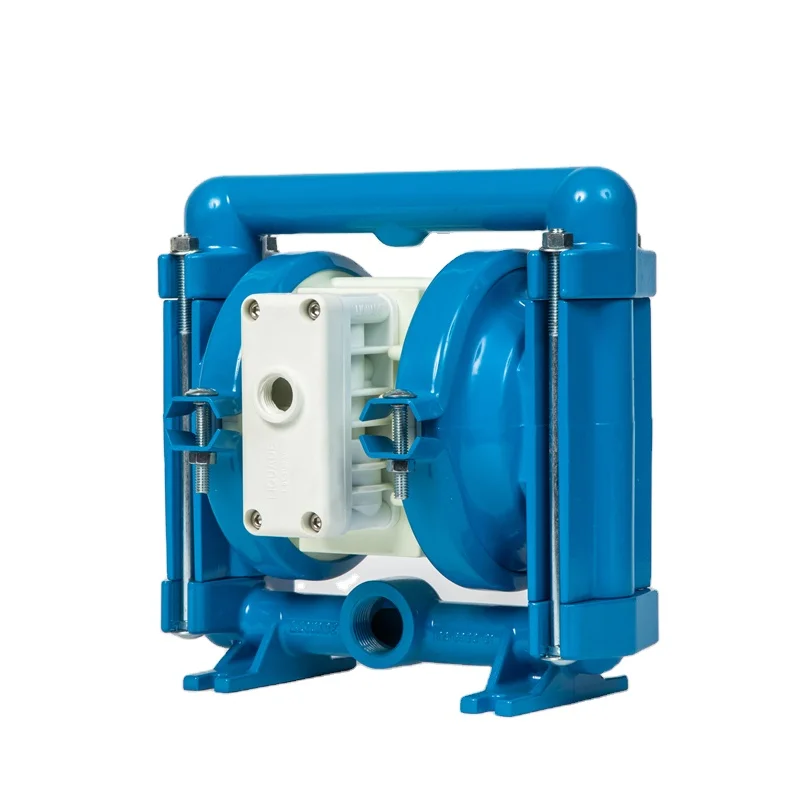
Piston-style mud pumps utilize a piston or plunger that travels back and forth in a chamber known as a cylinder. These pumps are also called “positive displacement” pumps because they literally push the fluid forward. This fluid builds up pressure and forces a spring-loaded valve to open and allow the fluid to escape into the discharge piping of the pump and then down the borehole. Since the expansion process is much smaller (almost insignificant) compared to a centrifugal pump, there is much lower energy loss. Plunger-style pumps can develop upwards of 15,000 psi for well treatments and hydraulic fracturing. Centrifugal pumps, in comparison, usually operate below 300 psi. If you are comparing most drilling pumps, centrifugal pumps operate from 60 to 125 psi and piston pumps operate around 150 to 300 psi. There are many exceptions and special applications for drilling, but these numbers should cover 80 percent of all equipment operating out there.
The restriction of putting a piston-style mud pump onto drilling rigs has always been the physical size and weight to provide adequate flow and pressure to your drilling fluid. Because of this, the industry needed a new solution to this age-old issue.
Enter Cory Miller of Centerline Manufacturing, who I recently recommended for recognition by the National Ground Water Association (NGWA) for significant contributions to the industry.
As the senior design engineer for Ingersoll-Rand’s Deephole Drilling Business Unit, I had the distinct pleasure of working with him and incorporating his Centerline Mud Pump into our drilling rig platforms.
In the late ’90s — and perhaps even earlier — Ingersoll-Rand had tried several times to develop a hydraulic-driven mud pump that would last an acceptable life- and duty-cycle for a well drilling contractor. With all of our resources and design wisdom, we were unable to solve this problem. Not only did Miller provide a solution, thus saving the size and weight of a typical gear-driven mud pump, he also provided a new offering — a mono-cylinder mud pump. This double-acting piston pump provided as much mud flow and pressure as a standard 5 X 6 duplex pump with incredible size and weight savings.
The true innovation was providing the well driller a solution for their mud pump requirements that was the right size and weight to integrate into both existing and new drilling rigs. Regardless of drill rig manufacturer and hydraulic system design, Centerline has provided a mud pump integration on hundreds of customer’s drilling rigs. Both mono-cylinder and duplex-cylinder pumps can fit nicely on the deck, across the frame or even be configured for under-deck mounting. This would not be possible with conventional mud pump designs.
Centerline stuck with their original design through all of the typical trials and tribulations that come with a new product integration. Over the course of the first several years, Miller found out that even the best of the highest quality hydraulic cylinders, valves and seals were not truly what they were represented to be. He then set off on an endeavor to bring everything in-house and began manufacturing all of his own components, including hydraulic valves. This gave him complete control over the quality of components that go into the finished product.
The second generation design for the Centerline Mud Pump is expected later this year, and I believe it will be a true game changer for this industry. It also will open up the application to many other industries that require a heavier-duty cycle for a piston pump application.

Your water pump is primed and the liquid is flowing… kind of. One of the more common problems with water pumps is a reduced or lower than expected water flow. When you need to dewater the jobsite, low flow means more downtime for the crew, costing money and putting deadlines at risk. Often, low water flow is less about your water pump and more to do with the situation. Below are a few things to review to troubleshoot water pump problems involving low water flow.
The greater the distance a pump has to pull the water, the lower the flow rate will be. Get too far from the water source and the more power is dedicated to ‘sucking’ the water and less to discharging, reducing the flow rate.
Typically, pumps should be with 20 feet of the water source. Depending on the typography, how high the pump is relative to the water, the flow may be reduced at even shorter distances. Your pump has individual specification, so be sure you read the spec and operate within them.
Your pump is designed to operate with a certain diameter input line. In some cases, we have seen people attach a smaller than recommended hose or line (using a reduction couplings). Depending on the intake line you use, it is also possible that the line crimps, or is “sucked in” on itself.
Debri blockage is a common problem. With murky water it can be hard to see the intake hose. But, operators should check to be sure there is no debris blocking the intake. The blockage usually happens at the filter as it does it’s job to prevent damage to the water pump. Remove the debri and reposition the hose to start pumping again.
The intake filter or screen can also be the culprit even without debri . While you must ensure the filter is fine enough to prevent damaging solids from entering the pump, too fine a filter for the water pump will restrict the flow right as the water enters the intake. Be sure the filter is proper for the pump.
Centrifugal water pumps are designed to operate with the impeller going in one direction. If it is going the opposite direction, the pump will not operate properly. This can happen if the electrical connections to the electric motor is not established correctly. Review the electric motors setup and user instructions to ensure your connections are correct.
Whether you are dewatering a jobsite, irrigating a field or applying your water pump for any other purpose, low flow is an issue. In some cases, like a firefighting pump, it can be a matter of life-or-death. One way to minimize onsite issue it to check all your equipment on a regular basis, replacing worn parts and performing maintenance as needed. But when confronted with low flow rates, follow the above steps and you’ll be able to get your water pump back in action, and your crew back to work.
AfghanistanAlbaniaAlgeriaAmerican SamoaAndorraAngolaAnguillaAntarcticaAntigua and BarbudaArgentinaArmeniaArubaAustraliaAustriaAzerbaijanBahamasBahrainBangladeshBarbadosBelarusBelgiumBelizeBeninBermudaBhutanBoliviaBonaire, Sint Eustatius and SabaBosnia and HerzegovinaBotswanaBouvet IslandBrazilBritish Indian Ocean TerritoryBrunei DarussalamBulgariaBurkina FasoBurundiCabo VerdeCambodiaCameroonCanadaCayman IslandsCentral African RepublicChadChileChinaChristmas IslandCocos IslandsColombiaComorosCongoCongo, Democratic Republic of theCook IslandsCosta RicaCroatiaCubaCuraçaoCyprusCzechiaCôte d"IvoireDenmarkDjiboutiDominicaDominican RepublicEcuadorEgyptEl SalvadorEquatorial GuineaEritreaEstoniaEswatiniEthiopiaFalkland IslandsFaroe IslandsFijiFinlandFranceFrench GuianaFrench PolynesiaFrench Southern TerritoriesGabonGambiaGeorgiaGermanyGhanaGibraltarGreeceGreenlandGrenadaGuadeloupeGuamGuatemalaGuernseyGuineaGuinea-BissauGuyanaHaitiHeard Island and McDonald IslandsHoly SeeHondurasHong KongHungaryIcelandIndiaIndonesiaIranIraqIrelandIsle of ManIsraelItalyJamaicaJapanJerseyJordanKazakhstanKenyaKiribatiKorea, Democratic People"s Republic ofKorea, Republic ofKuwaitKyrgyzstanLao People"s Democratic RepublicLatviaLebanonLesothoLiberiaLibyaLiechtensteinLithuaniaLuxembourgMacaoMadagascarMalawiMalaysiaMaldivesMaliMaltaMarshall IslandsMartiniqueMauritaniaMauritiusMayotteMexicoMicronesiaMoldovaMonacoMongoliaMontenegroMontserratMoroccoMozambiqueMyanmarNamibiaNauruNepalNetherlandsNew CaledoniaNew ZealandNicaraguaNigerNigeriaNiueNorfolk IslandNorth MacedoniaNorthern Mariana IslandsNorwayOmanPakistanPalauPalestine, State ofPanamaPapua New GuineaParaguayPeruPhilippinesPitcairnPolandPortugalPuerto RicoQatarRomaniaRussian FederationRwandaRéunionSaint BarthélemySaint Helena, Ascension and Tristan da CunhaSaint Kitts and NevisSaint LuciaSaint MartinSaint Pierre and MiquelonSaint Vincent and the GrenadinesSamoaSan MarinoSao Tome and PrincipeSaudi ArabiaSenegalSerbiaSeychellesSierra LeoneSingaporeSint MaartenSlovakiaSloveniaSolomon IslandsSomaliaSouth AfricaSouth Georgia and the South Sandwich IslandsSouth SudanSpainSri LankaSudanSurinameSvalbard and Jan MayenSwedenSwitzerlandSyria Arab RepublicTaiwanTajikistanTanzania, the United Republic ofThailandTimor-LesteTogoTokelauTongaTrinidad and TobagoTunisiaTurkmenistanTurks and Caicos IslandsTuvaluTürkiyeUS Minor Outlying IslandsUgandaUkraineUnited Arab EmiratesUnited KingdomUnited StatesUruguayUzbekistanVanuatuVenezuelaViet NamVirgin Islands, BritishVirgin Islands, U.S.Wallis and FutunaWestern SaharaYemenZambiaZimbabweÅland Islands

This website is using a security service to protect itself from online attacks. The action you just performed triggered the security solution. There are several actions that could trigger this block including submitting a certain word or phrase, a SQL command or malformed data.

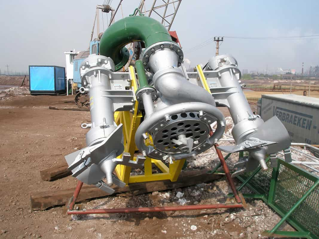
Every trenchless project needs a method to remove excavated soil from the bore. Some methods use augers, while others could even be hand excavated. But, many trenchless construction projects use slurry systems for this purpose.
A slurry mixture – or mud containing water, bentonite and other additives – is pumped down the drill string. The mud pushes out of the drilling head itself, helping to lubricate the side walls of the bore. This makes it easier for the pipe to slide through the soil. Slurry also maintains a pressure inside the bore to withstand the effects of groundwater pushing in. A positive pressure inside the bore is important to prevent tunnel collapse. Microtunneling and HDD are typical trenchless methods which use a slurry system. (For more on mud, check out Bentonite and the Use of Drilling Mud in Trenchless Projects.)
Slurry pumps supply enough pressure to push the mud through the bore, carrying spoil from the excavation back to the surface with it. From there it enters a separation unit to remove the solids before being recycled in the system. These pumps operate in harsh conditions and often require both high pressures and high flow rates.
Sizing a slurry pump correctly is a critical part of the pump selection process. This ensures that it will operate within its design parameters, avoiding premature pump failures and costly downtime.
There are a wide variety of types of pump, including reciprocating, diaphragm and centrifugal pumps. Many slurry systems use centrifugal pumps because of their robustness and performance characteristics. A centrifugal pump works by rotating an impeller which pushes the slurry through the system.
Pump capacity is primarily defined by two parameters: head pressure and flow rate. Manufacturers supply each pump with a pump curve where pressure and flow are plotted against each other. It is this curve that we use to determine whether a pump is suitable for our application.
Chemical Engineering describes a detailed process for engineers to follow when sizing a pump. The more complex the application, the more important it is to have expert help in establishing the pump design characteristics needed. Nevertheless, there are some fundamental steps that can be applied in every situation.
Dynamic head is effectively the pressure at the discharge of the pump in order to supply the energy needed to push the slurry through the system. A major factor that affects the dynamic head is changes in level from the slurry supply tank to the lowest point in the bore and back up again. The pump must overcome the forces of gravity to push the mud back out of the ground.
Another significant factor is the friction of the system. As the slurry passes through the drill pipe and back up to the surface, it encounters friction against the surface walls of the pipe. Slurry pumps must provide enough energy to overcome these forces of friction too.
Besides supplying sufficient dynamic head based on the calculations above, a slurry pump must also push the required volume of slurry through the system. This is defined in terms of flow rate. The flow rate required for a trenchless project is heavily dependent on the soil conditions and the size of the bore. Sandy soils need the lowest volume of slurry to carry the spoil to the surface in an HDD project. But, shale conditions may require up to 20 times as much. (To learn more about ground conditions, see When Ground Improvement is Needed During Trenchless Rehabilitation.)
No pump operates at 100 percent efficiency. In fact, efficiencies can range from as low as 50 percent up to over 90 percent. This means that from 10 to 50 percent of the energy you supply to the pump is not actually used to move the slurry through the system – it is lost. The better the efficiency of the pump, the lower your operating costs will be. However, efficiency is based on where on the pressure/flow curve the pump is operating.
A pump curve is essentially a graphic representation of the performance of a pump. If the head and flow rate of your application sits on or below the pump curve, then the pump is capable of performing that task. A steep curve means that it can generate a lot of head but limited flow rate. Flat pump curves represent pumps that can generate high flows but have a limited head pressure.
Pump manufacturers actually supply a series of curves for each pump that represent the pump’s performance for different diameter impellers. Efficiency curves can be overlaid on the pump performance curve to indicate where the pump is operating in its best efficiency range.
Selecting an efficient pump is important, as it saves on operating costs like electricity or generator fuel. One pump may be cheaper to buy but cost much more to run in the long term. It may be better to buy a more expensive pump up front, but one that has a good efficiency and lowers your operating costs.
Operating on the left side of the pump curve will lead to symptoms of temperature rise, noisy operation due to cavitation and vibration, which will ultimately result in low bearing and seal life and regular maintenance outages.
When analyzing pump failures, it is important to look at the whole system and not just the pump itself. Monitor and record pressure readings in the mud circulation system and check friction calculations. An error in these calculations could mean that you have the wrong pump for your service and therefore have a solution that is prone to failure.
As in most process applications using pumps, it is often not the cost of a pump repair that is the primary problem. The problem is the interruption to the project while the repair is being executed.

The 2,200-hp mud pump for offshore applications is a single-acting reciprocating triplex mud pump designed for high fluid flow rates, even at low operating speeds, and with a long stroke design. These features reduce the number of load reversals in critical components and increase the life of fluid end parts.
The pump’s critical components are strategically placed to make maintenance and inspection far easier and safer. The two-piece, quick-release piston rod lets you remove the piston without disturbing the liner, minimizing downtime when you’re replacing fluid parts.

I am often asked to visit plant sites to consult on problems regarding inadequate flow rates in two-pump systems. These plants are usually more than 10 years old, and the commissioning operators and engineers are no longer present. Plant output requirements have increased, and/or the equipment is simply old and less efficient. Either way, the desired outcome is to obtain more flow through the system.
In a typical scenario, someone observes there is an additional installed pump and decides the solution is to simply start and operate the second pump. To an untrained person who sees two pumps installed in the same system, it seems logical that operating the second pump in parallel will increase the flow. This may work in some instances but often does not. When the system is not designed for two (or more) pumps to operate at the same time (in parallel), it will not take long for both pumps to experience issues.
Two pumps set up to run individually and/or in parallel. In other words, pumps can run in parallel or separately, covering a wide range of expected flows.
To find the solution to the problem, the first thing I ask for is the system curve. The curve is often not available, so I work with plant personnel to calculate and develop the system curve. Once we overlay the system curve on the pump curves, the issue and possible solutions become readily apparent.
In many cases, the system designer may have designed the system to have one pump do all of the required work (100 percent duty pump) with a second pump (also known as the redundant pump, installed spare, 100 percent spare or backup pump) ready for operation so the first pump can be removed from service without disturbing the production process. The pumps and their associated motors and controllers are each designed for 100 percent duty.
The intersection of the single pump curve and the system curve should be near the best efficiency point (BEP) for the pump. In these types of cases, the piping system is not designed for both pumps to operate at the same time. The pipe size is typically too small to efficiently handle the higher flows and presents a huge friction loss if both pumps are operated. Another way to think of this situation is the system curve is steep—not flat—for two-pump operation.
If the system is designed for both pumps to operate at the same time, then the system curve will, by design, be flatter overall and present less friction. You can also think of undesired friction as wasted horsepower, which translates to higher electrical costs.
This column is not meant to explain in detail why one curve is steep and the other is flat. The important point to note is the steeper curves represent more friction loss as you attempt to pump more flow through the pipe. For this article, it is sufficient to say that if the system is designed for parallel pumping, the system curve will tend to be flatter.
Figure 1 depicts a properly designed system for parallel pump operations. With one pump operating (Intersection Point 1), the system curve remains relatively flat, and flow is X with corresponding head Y.
When the second pump is started (Intersection Point 2), the friction presented by the higher flows yields a slightly steeper system curve. While the flow will be more than X, please note that it will not attain magnitude 2X.
Figure 2 shows that if one of the pumps is an installed spare and both pumps are operated at the same time, then the additional flow is too much for the given pipe diameter, and the result is a high friction loss.
Looking at Operating Point 2, you can see that starting the second pump has yielded little additional flow. It could be in the range of X flow plus 10 percent, but in many cases it is even worse. This is why starting the second pump can actually kill both pumps.
In these situations, there will always be a strong pump and a weak pump. Even if the pumps were designed and manufactured to be identical, there is always some nuance in one of the pumps and in the system that will prevent the pumps from being identical.
The stronger pump will attempt to take the full load (as presented by the system). The stronger pump will run far right on its curve (a condition called runout) and have issues with vibration and cavitation (net positive suction head [NPSH] and flow angle incidence recirculation) that will manifest as damaged impellers as well as short-lived bearings and mechanical seals. At the same time, the weak pump will run at low to no flow and have similar issues because it is operating at the far left side of the curve. It is not uncommon for the stronger pump to develop sufficient pressure to close the discharge check valve on the weaker pump, consequently forcing it to operate at a shutoff head (zero flow rate).
Figure 3 shows the operation of Pump 1 (Intersection Point 1) and the subsequent parallel operation of Pump 2. A common misunderstanding is that if you start the second pump, the flow rate will double to Intersection Point 2. In reality, the actual operating point will be at Intersection Point 3. In a centrifugal pump system, the pump will always operate where the system curve dictates.
Pumps in a system that is not designed for parallel operation should not be operated at the same time except for brief intervals during switching operations. To do otherwise is likely to prematurely damage both pumps.
Often, a good system design is to have pumps in parallel because they can provide flexibility to match the flow to the load. This setup is also more reliable because it provides standby protection for a relatively high percentage of the full load in the event of one pump loss.
Different pump designs/models can operate together in parallel, but it is important that they have an identical shutoff head and similar specific speeds.
If the system is designed for parallel pumps, determine which pump is the stronger one by running one at a time and measuring the head at various flows. As a general rule, always start the weaker pump first.
You can overcome some of the mismatches in pump and system designs by using variable speed drives and carefully monitoring where each pump is on the curve, changing speeds as required to keep the load balanced.
When running one pump for small loads and then starting the second pump to pick up larger loads, do not let the first pump run out on its curve too far before the second pump is started. The first pump may be cavitating for some time before the second pump picks up. I see this happen often on systems designed to operate automatically. The designer often overlooks the NPSH margins at the right side of the curve.
Whether the pumps are in parallel or it is just two pumps in a one-pump system, I always recommend installing hour meters to track the operating hours. I have witnessed many mistakes resulting from decisions based on someone"s memory or record-keeping habits. Hour meters are inexpensive insurance. (Do you know when to change the oil in the pump?)
In a parallel pump system, whichever pump is started first must be capable of covering the full load presented by the system curve without overloading the driver or running out on its own curve.

We introduced parallel and series pumping systems in the January column of The Water Works with a discussion on parallel pumping installations and possible pitfalls. This month we continue the discussion with series pumping installations.
As opposed to a parallel pumping configuration, a series (often mistakenly referred to as a real booster pump system) pumping installation implies the entire discharged volume (flow rate) of source water working against a proportionally lower amount of the total head will be delivered from a water supply source (a source pump or pressurized water system) and immediately delivered to the inlet (suction) of an inline booster pump to elevate the combined system head (pressure) to the total dynamic head (TDH) in tandem.
An idealized scenario where two identical pumps are used to effectively double the discharge head from 150 feet to 300 feet at a common flow rate of 1000 gallons per minute is shown in Figure 1 (TDH: 1 + 1 = 2). In some cases, up to three to four pumps at different levels are used to generate the TDH in stages and at different intervals, with each pump adding its unique and individual value of head toward the resulting total head, all at a uniform flow rate.
Although the head delivered by each pump may be dissimilar, it is critical that all pumps used in a series pumping configuration are designed for and capable of accepting and producing the same flow (discharge) rate or range, preferably within the best efficiency window.
Even when using a variable frequency drive in many actual applications, depending on the use with each service condition, this type of wide variance in flow rate (more than 25%) between the primary and alternate conditions presents itself as a potentially ideal type of situation to consider using a series pumping installation.
This permits the source pump to be designed for a wider range of flow with a higher efficiency at the more frequently used alternate (usually lower) flow condition and with a lower operating efficiency at the less used primary condition. So long as the source pump is capable of the higher capacity primary condition flow rate from the well and well pump with sufficient head into the suction of the second stage, or booster pump, the system can be an efficient alternative to using a single pump.
As a rule of thumb, I have found a well/booster pump system is most efficient when the well pump is required to produce 50% to 75% of the total head, with the booster pump producing 25% to 50% of the total head at a common flow rate. This percentage range in a two-step pumping arrangement generally allows for the possibility of using the source pump only for the lower system demands.
It is also a valid scenario when an existing or lower horsepower well pump is present and desired to be retained which may be capable of producing the required higher flow rate but is not capable of the required higher head without boosting, the power supply is limited or not capable of starting a single large (50 HP for example) motor, or the client does not wish to use a variable frequency drive in the installation.
In this case, the well pump would generally be designed as a single speed, lower HP unit that would be capable of delivering the primary flow of 500 GPM into the booster pump and efficiently pumping at a reduced flow rate of 156 GPM at the required lower head (approximately 240 feet).
In our revised design example using a submersible well pump and end-suction centrifugal booster pump combination, we begin by examining and deducting the 90 feet well lift (pumping water level, PWL) added to the riser pipe and discharge friction loss (7 feet), which at 500 GPM totals an adjusted pumping water level (APWL) of 97 feet. This means, at a minimum, enough of the well pump’s head must be reserved to lift the water to the top of the well and into the booster pump under maximum flow conditions.
Typically, in these cases I try to add a minimum safety factor of no less than 10 psi (23 feet) to this value of head. I actually prefer to add 20 psi (46 feet) of reserve head to the APWL, when available, to account for a possible future decline in the PWL and to provide adequate inlet head into the booster pump at all times, which ensures the booster pump will not cavitate from inadequate inlet pressure or NPSHA.
Well lift (PWL) and riser pipe friction loss: 97 feet (90 feet + 7 feet riser pipe hf= 97 feet APWL) + 20 psi of booster pump inlet head: 46 feet = required minimum well pump head: 143 feet (55% of the total of 260 feet).
The alternate submersible well pump we have now selected is a 9-inch-diameter × five-stage bowl assembly (81.5% efficient) with a 25 HP motor, instead of the 50 HP sub motor originally selected. The revised design condition for this pump is now 500 GPM at 152 feet TDH, 9 feet more than required. The well pump curve is shown in Figure 2.
Originally required total system head (TDH): 260 feet (at 500 GPM) – less head from well pump: 152 feet (57.4% of 265 feet) = 108 feet + added inlet head for booster losses: 5 feet = required (net) booster pump head: 113 feet (42.6% of 265 feet).
The booster pump required COS of 500 GPM at 113 feet TDH can easily be met from an end-suction centrifugal pump as the required head may be too low for many multistage VTP or submersible units. The booster pump curve (Figure 3) indicates the booster pump will deliver 500 GPM at 116 feet TDH, 3 feet more than required (the booster pump impeller can be trimmed to fit precise conditions).
Unless otherwise determined, I routinely recommend adding 5 feet of head to the booster pump head requirement to account for the energy losses associated with the pump and manifold assembly.
In our example, an 18.60 BHP demand is calculated for the booster pump; therefore, a 20 HP motor is needed. The combined brake horsepower from both pumps is now: 23.55 HP (well pump) + 18.60 HP (booster pump) = 42.15 BHP, only 1.54% higher in BHP than the original single 50 HP submersible pump BHP of 41.50, indicative of an efficient pumping tandem.
Although the alternate condition of 156 GPM for the well pump is slightly less than the original design head of 240 feet (230 feet actual TDH or about 4 psi less pressure), after consultation with the client this small difference in delivery pressure is not felt to be important.
Incorporate a check valve bypass for primary pump operation.While this may seem a no-brainer, I have witnessed numerous examples where a system was designed with the primary or “source” pump always pushing water through and out the booster pump, even when the booster pump is disabled. In addition to the extreme and unnecessary head loss associated with routing the flow through the booster pump, this type of operation generally results in a slower speed rotation of the pump and motor.
This lower rotational speed of the booster pump and motor does not usually generate sufficient lubrication of the motor bearings. This will be outlined in our next column.
Be aware of possible system or booster pump overpressurization.This is one of the most critical considerations for a high-pressure (less than 150 psig) series pumping installation since the residual pressure or head developed from the source pump is added to the pressure (head) from the booster pump at a common flow rate to generate much higher finished pressure.
This is particularly true on irrigation applications using hard hose reels with big guns or other high-pressure systems. In extreme cases, particularly if the booster flow rate is throttled or reduced, the combined pressure can reach enough of a dangerous level to result in pipe or pump case rupture.
This type of risk is most apparent in high head applications using an end-suction centrifugal pump with a cast iron or plastic volute or the upper stages of a multistage vertical turbine or submersible pump used as the booster pump, especially when an inline booster pump or pressure-reducing valve is used for on/offline flow transition or pressure control.
As an illustration and using our well example: If the flow rate was totally shut down with both source and booster pumps running, the residual wellhead pressure could reach 255 feet (from well pump) + 145 feet (added from booster pump) = 400 feet TDH – 50 feet minimum SWL = 350 feet (152 psi).
While this pressure may not be immediately injurious to the pumping units or manifold, it could conceivably be higher than the pressure rating of the booster pump case or a lower pressure rated PVC pipeline, potentially resulting in bursting either of them.
The designer must always be aware of this potential, and if necessary, specify a ductile iron or steel volute or bowl assembly whenever the discharge pressure can exceed the maximum working pressure of the well or booster pump. This factor should be examined on every series pump design with effective measures—such as a high-pressure cutout switch or pressure relief valve incorporated into the design if needed to avoid serious equipment damage or personal injury.
Verify that the source pump is not overpumping.When applying a booster pump to an existing well installation, the well pump and, by association, the well may be asked to pump at a lower pressure and thus a higher flow rate than formerly the case. The designer should verify the well will not be operating above the safe capacity of the well and the well pump will not surge or overload at higher flows.
Use a low-pressure cutout and electrical interlock to operate and protect the booster pump.Incorporating a low-pressure cutoff switch is an effective and simple way of protecting the booster pump from dry running conditions. Although an inline flowmeter can be used for the same purpose, a pressure switch with a time delay is a much cheaper and more reliable alternative, plus it provides a method of automatically starting and stopping the booster pump, particularly for irrigation systems.
With systems in which the supply water is provided from a separate pressurized water source, a low-pressure cutoff switch is also an effective method of protecting the booster pump and supply from operating during extreme low-pressure conditions occurring with the source or from potentially developing negative pressures within a pressurized water system, such as booster pumps used in cities and water districts.
Using a minimum booster pump inlet operating pressure of 20 psig ensures adequate inlet pressure is always available to the booster pump and is not starved, nor is the water system functioning at potentially low or even negative pressures, which can introduce dangerous contaminants into the system.
In two-pump systems, using an electrical interlock between the booster pump control with the source pump control is also recommended to ensure the booster pump can run only when the source pump is operating.
Do not forget the well lift and head for well pumps.Once again, this is an important design factor when applying a booster pump to an existing well and pump. It is critical that adequate head developed by the well pump be reserved to lift the water from the well, plus deliver the needed flow rate into the booster pump.
This type of error can occur if the well has been pumping for years at one flow rate and associated water level and is asked (or assumed) to be able to operate at a higher flow rate without determining or verifying the revised pumping water level. If feasible, I recommend adding no less than 20 psi (46 feet) (10 psi, minimum) of head to the maximum pumping lift (in feet) as the minimum well pump design head.
Use extra precautions with well pumps.Although the procedure shown here for using an end-suction centrifugal pump as a booster pump can also apply to either a vertical turbine or submersible pump, when adding a pressurized pump or piping directly into the suction port of a vertical turbine pump, there are a few additional precautions to be observed.
The primary consideration relates to the axial thrust (downthrust) developed by the pump and resisted by the motor during high head service. In many cases the relatively low values of allowable downthrust in smaller vertical or submersible pump motors may not be adequate to resist the higher thrust developed from the pressure values associated with high-pressure booster (series) pumping.
In order to avoid these potential situations, I suggest the maximum downthrust rating for a motor intended for booster (series) service be initially checked and verified against the actual downthrust for adequacy, particularly if the design calls for prolonged operation at service conditions approaching the shutoff head of the booster pump or a 4- or 6-inch-diameter submersible motor is used as the booster pump driver. If needed, using a 175%-rated thrust bearing may be required for a VTP motor or a larger HP or diameter motor for a submersible application.
Conversely, in other extreme cases, modifying an existing VTP or submersible pump installation to generate a higher flow into a booster pump can lower the well pump’s discharge pressure enough to result in a potential upthrust condition to occur to the well pump or motor. This situation is much more common and sensitive for a shallow set (20 feet to 50 feet), high capacity mixed flow well pump. However, it can potentially occur to any well pump, particularly during startup, so designers are cautioned to verify this possible anomaly and correct by applying higher pressures against the well pump, especially during a pipeline fill or system startup.
Next, when using a submersible pump and motor for an inline booster pump application, it is just as important to generate an adequate velocity past the motor as it is for a well installation. Designers must verify the intended pump design either routes the inlet water into the bottom and past the motor or incorporates a motor-surrounding shroud with a sufficient annular velocity (less than or equal to .50 fps) to maintain adequate motor cooling.
Finally, in other cases, modifying a well pump to a higher flow rate for booster service can negatively impact the NPSHR (requirement) of the pump, especially for applications using a tailpipe with a suction lift upwards to the bowl assembly. In these examples, the designer must verify the well pump will not cavitate or lose prime during higher capacity demands.
In other cases using a high-speed submersible pump as the booster pump, the inlet head or submergence over the pump’s inlet may not be sufficient to avoid cavitation. This can generally be determined through an examination of the bowl’s NPSH and submergence requirements. The actual procedure and methods for using well pumps as canned booster pumps will be outlined in our next column.
Be cautious when using mismatched pumping units.Although most pumps with dissimilar H-Q curves will eventually find a common ground of flow to function, there are conditions in which a series pumping installation will not be effective using pumps with dissimilar curves. Certainly, the easiest way to avoid this is by using units in which the shape of both H-Q curves match or are similar throughout the range of flow.
However, units in which either pump is asked to produce more than 75%-80% of the total head may not be as efficient as simply using a single larger unit to perform the entire service. In some applications where the rated capacity of the booster pump is much higher than the source pump, errant operating conditions can occur, particularly during startup or line fill.
Surging conditions or a short duration loss of flow between the pumping units can occur where the booster pump can actually develop a severe loss of inlet head, creating a suction lift upon the source pump—causing a sudden but momentary loss of flow from the source into the booster pump, often resulting in air entrainment or vapor lock in the booster pump or piping manifold. This is usually rapidly supplanted by an immediate resumption of pumping.
In water well conditions, this can lead to hydraulic surging resulting in an undulating thrust condition upon the well pump and motor, possibly leading to premature failure. This situation can generally be avoided by making sure both pumps in a series configuration are designed for the same rough capacity range and that adequate discharge head is developed by the well pump under all flow conditions to avoid damaging upthrust.
To be certain, these potential conditions are rare in actual practice. However, designers are nonetheless cautioned to recognize the potential, and when present, ensure the booster pump design condition and flow range closely matches the flow rate range of the source system or pump or to incorporate an automatic control valve to maintain a minimal value of discharge pressure from the booster pump under all flow conditions.
This concludes this month’s edition of The Water Works. The upcoming July and October editions will apply many of these same concepts into the actual design and layout of a booster pump application or station for open or closed applications.
This website is using a security service to protect itself from online attacks. The action you just performed triggered the security solution. There are several actions that could trigger this block including submitting a certain word or phrase, a SQL command or malformed data.

Cleaning different surfaces and materials has never been easier than it has with a pressure washer. In south Louisiana, it takes no time for dust, dirt, mud, grass clippings, pollen, algae, moss, and more to overtake driveways, fences, stucco, decks, patios, and other surfaces.
Whether you are doing some regular maintenance around the home or need a pressure washer for commercial and industrial use, we have all the information you need based on decades of experience.
Bozeman Distributors builds and sells custom pressure washers, services, and repairs pressure washers and offers all of the accessories and solutions you need to make the most of your pressure washing tasks.
A pressure washer is a machine that uses a highly pressurized water spray to clean dirt, grime, grease, mud, paint, and other debris from vertical and horizontal surfaces.
Gasoline powered units provide the most portability. Based on your needs: homeowner, commercial operator or industrial user, the flow rate (gallons per minute – gpm) is more important than the pressure, in most cases. A combination of flow and pressure will provide efficient and effective cleaning in a short amount of time. If you have excessive pressure compared to the flow rate, you make a fog or a heavy mist. The water is atomized before it hits the surface. If you have excessive flow compared to the pressure, the water just flows over the surface and has less impact with the surface and provides minimum cleaning.
For most residential applications, 3.0gpm @ 1500psi to 2500psi is adequate. If you have lots of concrete, equipment to wash, etc. 4.0gpm to 5.0gpm up to 3500psi will make the job faster. Always be aware of the pressure you are applying to the surface you are cleaning. Too much pressure will damage the surface or force water into unwanted areas like around windows and frames, doors, etc. A surface can be damaged with 1500psi if you are not paying attention or using the wrong spray nozzle.
Give Bozeman a call to discuss your application. Do not be fooled by the box stores with the High Pressure Rating they place on most of their units with low flow rates.
The experts at Bozeman Distributors will be able to make the best recommendation for your pressure washing needs. Shop Local. Buy Local. Get Local Service.
Electric pressure washers are great for heavy-duty cleaning and washing. Electric pressure washers typically offer easier operation and maintenance. While you don’t need to have fuel on hand, you need an extension cord rated for the electrical load and distance from your power source. Electric pressure washers also tend to run more quietly. An electric pressure washer will be less expensive in terms of maintenance & ownership cost pertaining to gas and oil.
Fuel-powered pressure washers have a variety of benefits. The main one being that you aren’t tethered to an extension cord. This means that you can go anywhere at any time with your pressure washer to take care of the task at hand, providing you have an adequate water supply and water pressure. This pressure washer also tends to be more powerful than the electric alternative, making it ideal for heavy commercial and industrial cleanings.
Cleaning solutions, soaps, and detergents can be used in every type of pressure washer. Depending on the surface you are cleaning, there are a variety of different cleaning solutions. Whether you’re clearing away dirt, killing mold, moss, or algae, your pressure washer can handle many soaps that can enhance and maintain the cleaning that your pressure washing is doing.
Different surfaces require different cleaning techniques. A pressure washer is a great device to clean your concrete surfaces. Whether you are sprucing up your driveway, sidewalk, or patio, begin by clearing the surface of any debris. Always begin at the higher end of the surface and make a sweeping motion as you move down the area.
If you have a fence, deck, dock, or patio made of wood, the elements in south Louisiana can quickly take their toll. Dirt, dust, algae, moss, and other debris can discolor and deteriorate your wooden structures. A pressure washer can revive these areas. Specific detergents help remove and prevent the regrowth of mold. Use a higher-degree spay nozzle to prevent damaging the wood. Using a uniform distance, and always move the stream along the grain.
Using a power washer to clean stucco is not advised or recommended. Too much pressure will damage the stucco and penetrate the sub-surface, placing water into the wall. Use Low Pressure and High Volume. Give us a call for more details.
Stucco is a common material used on homes and businesses in south Louisiana. While it gathers the same dirt, dust, and algae that other surfaces do, it needs to be handled differently than other materials. This protective covering requires a fan pattern, which offers a softer yet effective pressure washing method. Start at the top of the surface and work your way down. Angle the nozzle at a 45 -degree angle and maintain a 24- inch distance.
There are a variety of pressure washing accessories that can make cleaning different surfaces easier than ever. Depending on the size or material of the surface you need clean, an attachment can make every job easier. Surface cleaners provide a wider surface area and protect from spraying debris into flowerbeds and other sensitive areas. Brushes are great for removing grime with little effort. Turbo tips can provide the extra power when and where you need it. These are only a few examples, and the team at Bozeman Distributors can recommend and supply the accessories you need for pressure washing tasks.
Pressure washers of all types can be repaired. They are essentially appliances like washers, driers, lawnmowers, and more. Whether you have a gas or electric pressure washer, whether you bought it from a private dealer or a big box store like Lowe’s or Home Depot, your pressure can be repaired. The expert staff at Bozeman Distributors has been building, repairing, and selling pressure washers to help Baton Rouge home and business owners.
For over 50 years, the expert staff at Bozeman Distributors have been helping Baton Rouge area home and business owners with their pressure washer purchasing, repair, replacement, and accessory needs.

The policy set forth below outlines the personal data that Power Zone Equipment may collect, how Power Zone Equipment uses and safeguards that data, and with whom we may share it. This policy is intended to provide notice to individuals regarding personal data in an effort to be compliant with the data privacy laws and regulations of the jurisdictions in which Power Zone Equipment operates.
Power Zone Equipment encourages our employees, independent contractors, customers, suppliers, commercial visitors, business associates, and other interested parties to read this policy. By using our website or submitting personal data to Power Zone Equipment by any other means, you acknowledge that you understand and agree to be bound by this policy, and agree that Power Zone Equipment may collect, process, transfer, use and disclose your personal data as described in this policy.
Power Zone Equipment is committed to maintaining all reasonable precautions to ensure the privacy and security of personal data gathered by Power Zone Equipment. During your use of our website or through other communications with Power Zone Equipment, personal data may be collected and processed by Power Zone Equipment. In general, Power Zone Equipment collects personal contact information (e.g. name, company, address, telephone number and e-mail address), which you knowingly provide either by registration, requesting quotes, answering questions or otherwise for use in our commercial relationship. At times we may collect additional personal data that you voluntarily provide, including, but not limited to, job title, additional contact information, date of birth, hobbies, areas of interest, and professional affiliations.
Power Zone Equipment’s website is intended to be used by Power Zone Equipment customers, commercial visitors, business associates, and other interested parties for business purposes. Personal data collected by Power Zone Equipment through its website or by other means is used in support of our commercial relationship with you, including, but not limited to, the processing of customer orders, orders from vendors, managing accounts, learning about customers’ needs, responding to inquiries, and providing access to information. Also, in compliance with the laws and regulations of the relevant jurisdiction to support our relationship with you:
If you choose not to have your personal data used to support our customer relationship (especially direct marketing or market research), we will respect your choice. We do not sell your personal data to third parties, nor share it with third parties except as set forth in this policy. Power Zone Equipment will retain your personal data as long as you maintain a customer relationship with Power Zone Equipment and/or if you have registered to receive marketing or other communication from Power Zone Equipment, until such time as you request that we delete such personal data.
For our customers in Switzerland and the European Union (EU), please note that Power Zone Equipment is a US based company. If you use our websites or web portals or, all information, including personal information, may be transferred to Power Zone Equipment (including subcontractors that may be maintaining and/or operating our website) in the United States and elsewhere and may be transferred to third parties that may be located anywhere in the world. Although this may include recipients of information located in countries where there may be a lower level of legal protection for your personal information than in your location country, we will protect your information in accordance with requirements applicable to your information and/or location. Specifically, for data transfers out of the EU, Power Zone Equipment will utilize data transfer agreements containing the Standard Contractual Clauses. By using our websites or web portals, you unambiguously consent to the transfer of your personal information and other information to the United States and elsewhere for the purposes and uses described herein.
When you access Power Zone Equipment’s websites or web portals, we may automatically (i.e., not by registration) collect non-personal data (e.g. type of Internet browser and operating system used, domain name of the website from which you came, number of visits, average time spent on the site, pages viewed). We may use this data and share it with our worldwide affiliates and related service providers to monitor the attractiveness of our websites and improve their performance or content. In this case, processing is performed on an anonymous basis and at Power Zone Equipment’s discretion.
In addition, certain online technical applications or other interactions you have with Power Zone Equipment may require the entry of business and technical data. By providing the requested information, you are consenting to the processing and storage of such information by Power Zone Equipment. Unless Power Zone Equipment is advised that you want this information removed from Power Zone Equipment’s server, such information may be retained by Power Zone Equipment and used for future commercial communications. A request for removal of this information can be made at the contact information provided below. Power Zone Equipment will take all reasonable precautions to assure that no such information will be provided or divulged to other third parties, except, if applicable, those third parties performing site hosting, maintenance, and related site service activities.
Power Zone Equipment will not knowingly collect personal data from children under the age of 18. Power Zone Equipment’s website(s) is not intended for individuals under 18 years of age
Power Zone Equipment will use personal data only in ways that are compatible with the purposes for which it was collected or subsequently authorized by you. While Power Zone Equipment will take reasonable steps to ensure that personal data is relevant to its intended use, accurate, complete, and current, Power Zone Equipment is also relying upon each individual to assist in providing accurate updates of his or her personal data.
Power Zone Equipment website(s) may contain “links” to websites owned and operated by third parties. By accessing these links, which are provided for your convenience, you will leave our site and will be subject to the privacy practices of the other website. This policy does not apply to any personal information you provide to unrelated third parties.
In general, Power Zone Equipment will only retain personal data for as long as needed for the specific purpose of processing and in accordance with Power Zone Equipment’s records management policy, or as otherwise required by the laws and regulations of a particular jurisdiction. For example, data will be retained during the time period that you are authorized to use Power Zone Equipment website(s), including any Power Zone Equipment tools accessible through our website(s). Upon termination of such authorization, your personal data related to use of Power Zone Equipment website(s) will be removed.
Upon request, Power Zone Equipment will grant individuals reasonable access to personal data that it holds about them. In addition, Power Zone Equipment will take reasonable steps to permit individuals to correct, amend, or delete information that is demonstrated to be inaccurate or incomplete. Power Zone Equipment also relies upon each individual to assist in providing accurate updates of his or her personal data. In order to access, correct, amend, or delete the personal data Power Zone Equipment holds about an individual, the individual should contact the following:
To the extent required by applicable law, Power Zone Equipment will grant individuals reasonable access to personal data that Power Zone Equipment holds about them and will take reasonable steps to permit such individuals to correct, amend, or delete information that Power Zone Equipment holds about them. Power Zone Equipment also relies upon each individual to assist in providing accurate updates of his or her personal data. In order to access, correct, amend, or delete the personal data Power Zone Equipment holds about an individual, the individual should contact his or her Power Zone Equipment commercial contact or contact us at the following email address:sales@powerzone.com.
Power Zone Equipment reserves the right to modify this policy from time to time in order that it accurately reflects the legal and regulatory environment and our data collection principles. When material changes are made to this policy, Power Zone Equipment will post the revised policy on our website.
all about well flow rate, well yield, and water quantity: this article series describes how we measure the amount of well water available and the well flow rate - the water delivery rate ability of various types of drinking water sources like wells, cisterns, dug wells, drilled wells, artesian wells and well and water pump equipment.
Is the well on the property being purchased? You"ll also want to know where the well equipment are located: the pump, pressure control switch, pressure tank, any reservoir tanks, and any water treatment equipment.
What we really need to know is the total quantity of water that can be drawn from the well and the quality of that water: is it potable, hard (mineral laden), smelly, dirty, requiring treatment for any aesthetic or health-concern contaminant?
There are three basic questions that must be asked about a private water supply provided from a well. It"s helpful to state them since otherwise a property buyer may receive only answers to some of these questions, all of which are critical:
WELL YIELD, SAFE LIMITS - explains the true volume of water that is available from a given well, the role of the static head, the flow rate, the pumping rate, storage tank reservoirs, and other factors that affect well life and changes in well yield.
That"s water potability. But further, are there other water contaminants that are not a health threat but which are aesthetic or even functional concerns such as color, sediment, water hardness, or water odors? You can see that a simple bacteria test to "pass" or "fail" a water well won"t address most of these questions.
The answers to this question usually describe the condition of the piping and well pump, not the condition of the well itself, though in some cases deliberate flow restrictors may have been installed at a building which is served by a well that has a very limited water quantity.
since that inflow rate ultimately sets the maximum rate at which water can be taken out of the well once any water reservoir in the well bore (the static head plus contents of any water storage tanks) has been consumed.
See WELL YIELD DEFINITION for a complete, detailed explanation of the factors that go into a true measurement of the capacity of a well to deliver water.
Watch out: If you are given a well flow rate that was measured over some shorter interval or worse, over some un-specified interval, you cannot be sure how the well will perform in actual use. For example someone may measure a pseudo-well-flow rate by just measuring the well output at the pump for a few minutes, or at a bathtub spigot or an outdoor hose bib.
Because well flow rates for many water wells are not constant but rather may diminish from an initial maximum in gallons per minute to a lower but sustainable flow rate, these short well flow tests can be misleading.
Brief water flow tests may actually just be measuring the rate that the well pump draws water out of the well bore - pumping out of the water reservoir in the well bore itself. This static head pumpout is not the well"s sustainable water delivery capacity.
This sketch, courtesy of Carson Dunlop Associates (found at page bottom, Click to Show or Hide) offers a graphic explanation of well static head. The static head in a well is is not the total amount of water than can be pumped out of the well, it"s just where
Based on simple geometry & the formula for the volume of a cylinder: we calculate the area of a cross section, or top, or bottom of the cylinder, then multiply that area by the cylinder"s height.
Watch out when estimating how much water is in the well. The depth of the well from bottom to top of the ground is usually not the height of actual water in the well.
The height of water column inside the well and available to the pump is less than the total well depth. Except in artesian walls the water column does not extend from the well bottom to the top of the ground.
In this sketch, distance (h) is the height of the "static head" = static head volume - the total volume of water available to the pump when the well has rested and fully-recovered.
The static head volume in a drilled well extends from the very bottom of the pump (since water can"t jump up to the pump) upwards to the highest point that water reaches inside the well casing when the well has rested and reached its normal maximum height.
(c) well bottom clearance: our well pump or foot valve (if the pump is not in the well) was placed 5" off of the well bottom © in the sketch,


 8613371530291