
mud pump used in drilling rig free sample

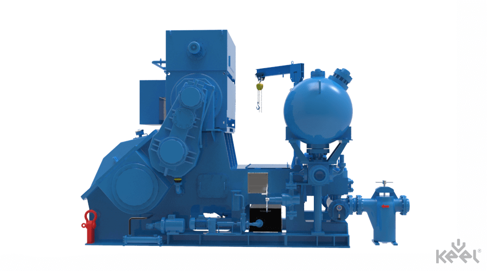
The 2,200-hp mud pump for offshore applications is a single-acting reciprocating triplex mud pump designed for high fluid flow rates, even at low operating speeds, and with a long stroke design. These features reduce the number of load reversals in critical components and increase the life of fluid end parts.
The pump’s critical components are strategically placed to make maintenance and inspection far easier and safer. The two-piece, quick-release piston rod lets you remove the piston without disturbing the liner, minimizing downtime when you’re replacing fluid parts.

Created specifically for drilling equipment inspectors and others in the oil and gas industry, the Oil Rig Mud Pump Inspection app allows you to easily document the status and safety of your oil rigs using just a mobile device. Quickly resolve any damage or needed maintenance with photos and GPS locations and sync to the cloud for easy access. The app is completely customizable to fit your inspection needs and works even without an internet signal.Try Template
Fulcrum helps us improve our processes and make our work environment safer by streamlining inspections, surfacing inspection-related insights, and managing follow-up actions. Once you close the loop from action to insight to further action, the possibilities are limitless.
Fulcrum lets employees on the floor who actually are building the product take ownership. Everyone’s got a smartphone. So now they see an issue and report it so it can be fixed, instead of just ignoring it because that’s the way it’s always been done.
One of the big things you can’t really measure is buy-in from employees in the field. People that didn’t want to go away from pen and paper and the old way of doing things now come to us and have ideas for apps.
Easy to custom make data collection forms specific to my needs. Very flexible and I can add or adjust data collection information when I need it. The inclusion of metadata saves a lot of time.
Fulcrum is, without a doubt, the best thing I"ve done for my business in regards to cost saving and time efficiency. Support is very good and help, on the rare occasions it"s required, is never far away.

When choosing a size and type of mud pump for your drilling project, there are several factors to consider. These would include not only cost and size of pump that best fits your drilling rig, but also the diameter, depth and hole conditions you are drilling through. I know that this sounds like a lot to consider, but if you are set up the right way before the job starts, you will thank me later.
Recommended practice is to maintain a minimum of 100 to 150 feet per minute of uphole velocity for drill cuttings. Larger diameter wells for irrigation, agriculture or municipalities may violate this rule, because it may not be economically feasible to pump this much mud for the job. Uphole velocity is determined by the flow rate of the mud system, diameter of the borehole and the diameter of the drill pipe. There are many tools, including handbooks, rule of thumb, slide rule calculators and now apps on your handheld device, to calculate velocity. It is always good to remember the time it takes to get the cuttings off the bottom of the well. If you are drilling at 200 feet, then a 100-foot-per-minute velocity means that it would take two minutes to get the cuttings out of the hole. This is always a good reminder of what you are drilling through and how long ago it was that you drilled it. Ground conditions and rock formations are ever changing as you go deeper. Wouldn’t it be nice if they all remained the same?
Centrifugal-style mud pumps are very popular in our industry due to their size and weight, as well as flow rate capacity for an affordable price. There are many models and brands out there, and most of them are very good value. How does a centrifugal mud pump work? The rotation of the impeller accelerates the fluid into the volute or diffuser chamber. The added energy from the acceleration increases the velocity and pressure of the fluid. These pumps are known to be very inefficient. This means that it takes more energy to increase the flow and pressure of the fluid when compared to a piston-style pump. However, you have a significant advantage in flow rates from a centrifugal pump versus a piston pump. If you are drilling deeper wells with heavier cuttings, you will be forced at some point to use a piston-style mud pump. They have much higher efficiencies in transferring the input energy into flow and pressure, therefore resulting in much higher pressure capabilities.
Piston-style mud pumps utilize a piston or plunger that travels back and forth in a chamber known as a cylinder. These pumps are also called “positive displacement” pumps because they literally push the fluid forward. This fluid builds up pressure and forces a spring-loaded valve to open and allow the fluid to escape into the discharge piping of the pump and then down the borehole. Since the expansion process is much smaller (almost insignificant) compared to a centrifugal pump, there is much lower energy loss. Plunger-style pumps can develop upwards of 15,000 psi for well treatments and hydraulic fracturing. Centrifugal pumps, in comparison, usually operate below 300 psi. If you are comparing most drilling pumps, centrifugal pumps operate from 60 to 125 psi and piston pumps operate around 150 to 300 psi. There are many exceptions and special applications for drilling, but these numbers should cover 80 percent of all equipment operating out there.
The restriction of putting a piston-style mud pump onto drilling rigs has always been the physical size and weight to provide adequate flow and pressure to your drilling fluid. Because of this, the industry needed a new solution to this age-old issue.
Enter Cory Miller of Centerline Manufacturing, who I recently recommended for recognition by the National Ground Water Association (NGWA) for significant contributions to the industry.
As the senior design engineer for Ingersoll-Rand’s Deephole Drilling Business Unit, I had the distinct pleasure of working with him and incorporating his Centerline Mud Pump into our drilling rig platforms.
In the late ’90s — and perhaps even earlier — Ingersoll-Rand had tried several times to develop a hydraulic-driven mud pump that would last an acceptable life- and duty-cycle for a well drilling contractor. With all of our resources and design wisdom, we were unable to solve this problem. Not only did Miller provide a solution, thus saving the size and weight of a typical gear-driven mud pump, he also provided a new offering — a mono-cylinder mud pump. This double-acting piston pump provided as much mud flow and pressure as a standard 5 X 6 duplex pump with incredible size and weight savings.
The true innovation was providing the well driller a solution for their mud pump requirements that was the right size and weight to integrate into both existing and new drilling rigs. Regardless of drill rig manufacturer and hydraulic system design, Centerline has provided a mud pump integration on hundreds of customer’s drilling rigs. Both mono-cylinder and duplex-cylinder pumps can fit nicely on the deck, across the frame or even be configured for under-deck mounting. This would not be possible with conventional mud pump designs.
Centerline stuck with their original design through all of the typical trials and tribulations that come with a new product integration. Over the course of the first several years, Miller found out that even the best of the highest quality hydraulic cylinders, valves and seals were not truly what they were represented to be. He then set off on an endeavor to bring everything in-house and began manufacturing all of his own components, including hydraulic valves. This gave him complete control over the quality of components that go into the finished product.
The second generation design for the Centerline Mud Pump is expected later this year, and I believe it will be a true game changer for this industry. It also will open up the application to many other industries that require a heavier-duty cycle for a piston pump application.
A well-placed suction stabilizer can also prevent pump chatter. Pump chatter occurs when energy is exchanged between the quick opening and closing of the reciprocating pump’s valves and the hammer effect from the centrifugal pump. Pump isolation with suction stabilizers is achieved when the charge pumps are isolated from reciprocating pumps and vice versa. The results are a smooth flow of pumped media devoid of agitating energies present in the pumped fluid.
Suction stabilizer units can mitigate most of the challenges related to pulsations or pressure surges, even in the most complex piping conditions. The resulting benefits prevent expensive unplanned downtime and decrease costs and inconvenience associated with system replacements and repairs.

If you ended up on this page doing normal allowed operations, please contact our support at support@mdpi.com. Please include what you were doing when this page came up and the Ray ID & Your IP found at the

The drilling operations app was designed specifically for the mud pump area in the drill rig, and covers relevant safety topics, including drilling mud level, drilling equipment safety, pipe pressure, drilling process and more.
The oil and gas rig equipment app can be customized for different drilling rig locations. Once the drilling equipment and rig floor have been inspected, users can sign off on the results electronically.

Instead of using paper checklists when out in the field, drilling contractors and rig inspection services can generate a new inspection form from anywhere and the results are saved electronically.
Specifically designed for drilling companies and others in the oil and gas industry, the easy to use drilling rig inspections app makes it easy to log information about the drill rigs, including details about the drill rigs operators, miles logged and well numbers. The inspection form app covers everything from the mud pump areas and mud mixing area to the mud tanks and pits, making it easy to identify areas where preventative maintenance is needed. The drilling rig equipment checklist also covers health and safety issues, including the availability of PPE equipment, emergency response and preparedness processes, and other critical elements of the drilling process and drill press equipment.

There are many different ways to drill a domestic water well. One is what we call the “mud rotary” method. Whether or not this is the desired and/or best method for drilling your well is something more fully explained in this brief summary.
One advantage of drilling with compressed air is that it can tell you when you have encountered groundwater and gives you an indication how much water the borehole is producing. When drilling with water using the mud rotary method, the driller must rely on his interpretation of the borehole cuttings and any changes he can observe in the recirculating fluid. Mud rotary drillers can also use borehole geophysical tools to interpret which zones might be productive enough for your water well.
The mud rotary well drilling method is considered a closed-loop system. That is, the mud is cleaned of its cuttings and then is recirculated back down the borehole. Referring to this drilling method as “mud” is a misnomer, but it is one that has stuck with the industry for many years and most people understand what the term actually means.
The water is carefully mixed with a product that should not be called mud because it is a highly refined and formulated clay product—bentonite. It is added, mixed, and carefully monitored throughout the well drilling process.
The purpose of using a bentonite additive to the water is to form a thin film on the walls of the borehole to seal it and prevent water losses while drilling. This film also helps support the borehole wall from sluffing or caving in because of the hydraulic pressure of the bentonite mixture pressing against it. The objective of the fluid mixture is to carry cuttings from the bottom of the borehole up to the surface, where they drop out or are filtered out of the fluid, so it can be pumped back down the borehole again.
When using the mud rotary method, the driller must have a sump, a tank, or a small pond to hold a few thousand gallons of recirculating fluid. If they can’t dig sumps or small ponds, they must have a mud processing piece of equipment that mechanically screens and removes the sands and gravels from the mixture. This device is called a “shale shaker.”
The fluid mixture must have a gel strength sufficient to support marble-size gravels and sand to the surface when the fluid is moving. Once the cuttings have been carried to the surface and the velocity of the fluid allowed to slow down, the fluid is designed to allow the sand and gravel to drop out.
The driller does not want to pump fine sand through the pump and back down the borehole. To avoid that, the shale shaker uses vibrating screens of various sizes and desanding cones to drop the sand out of the fluid as it flows through the shaker—so that the fluid can be used again.
When the borehole has reached the desired depth and there is evidence that the formation it has penetrated will yield enough water, then it’s time to make the borehole into a well.
Before the well casing and screens are lowered into the borehole, the recirculating fluid is slowly thinned out by adding fresh water as the fluid no longer needs to support sand and gravel. The driller will typically circulate the drilling from the bottom up the borehole while adding clear water to thin down the viscosity or thickness of the fluid. Once the fluid is sufficiently thinned, the casing and screens are installed and the annular space is gravel packed.
Gravel pack installed between the borehole walls and the outside of the well casing acts like a filter to keep sand out and maintain the borehole walls over time. During gravel packing of the well, the thin layer of bentonite clay that kept the borehole wall from leaking drilling fluid water out of the recirculating system now keeps the formation water from entering the well.
This is where well development is performed to remove the thin bentonite layer or “wall cake” that was left behind. Various methods are used to remove the wall cake and develop the well to its maximum productivity.
Some drillers use compressed air to blow off the well, starting at the first screened interval and slowly working their way to the bottom—blowing off all the water standing above the drill pipe and allowing it to recover, and repeating this until the water blown from the well is free of sand and relatively clean. If after repeated cycles of airlift pumping and recovery the driller cannot find any sand in the water, it is time to install a well development pump.
Additional development of the well can be done with a development pump that may be of a higher capacity than what the final installation pump will be. Just as with cycles of airlift pumping of the well, the development pump will be cycled at different flow rates until the maximum capacity of the well can be determined. If the development pump can be operated briefly at a flow rate 50% greater than the permanent pump, the well should not pump sand.
Mud rotary well drillers for decades have found ways to make this particular system work to drill and construct domestic water wells. In some areas, it’s the ideal method to use because of the geologic formations there, while other areas of the country favor air rotary methods.
Some drilling rigs are equipped to drill using either method, so the contractor must make the decision as to which method works best in your area, for your well, and at your point in time.
To learn more about the difference between mud rotary drilling and air rotary drilling, click the video below. The video is part of our “NGWA: Industry Connected” YouTube series:
Gary Hix is a Registered Professional Geologist in Arizona, specializing in hydrogeology. He was the 2019 William A. McEllhiney Distinguished Lecturer for The Groundwater Foundation. He is a former licensed water well drilling contractor and remains actively involved in the National Ground Water Association and Arizona Water Well Association.
To learn more about Gary’s work, go to In2Wells.com. His eBooks, “Domestic Water Wells in Arizona: A Guide for Realtors and Mortgage Lenders” and “Shared Water Wells in Arizona,” are available on Amazon.
A fast and efficient method of drilling, mud rotary drilling is effective in a wide range of geological formations, including sand, silt, clay, gravel, cobbles, and boulders. Not hindered by the presence of groundwater, a mud drill is also used for coring bedrock.
With the necessary torque for powerful rotation, new and seasoned operators find the Geoprobe® line of geotechnical drilling rigs and combination drilling rigs make for an effective mud drill thanks to:
With rig service shops in Pennsylvania, Kansas, and Florida, you’ll have industry-leading drill rig service support nearby for your routine maintenance or more in-depth rig remounting and refurbishment work - keeping your mud drill in the field earning dollars. Our service technicians are backed by our team of engineers to ensure solutions not bandaids to issues. And our production processes mean your mud drill is constructed consistently and tested thoroughly to ensure easier service support.
Engineered with efficiency and ease in mind, investing in a Geoprobe® mud drill simplifies your sampling while reliably ramping up production and rig utilization rates.
Our team of engineers thrives on collaborating with drillers while they continually innovate new designs for our mud drill line. Our goal is to make your job faster, safer, and easier. Partner with us and we"ll work to decrease your mud drill downtime while increasing your family time.

When you"re seeking the field flexibility to complete your drilling faster, easier and safer, count on Geoprobe® drill rigs engineered for versatility and manufactured for reliability. Industry leaders depend on our ongoing commitment to innovation and industry-leading customer support to advance their business ahead of the competition. Digital readouts providing instant feedback, enhanced safety features, easy operation, and availability of training options mean veteran drillers find their jobs simplified while new drillers build confidence, making them productive as they"re quickly coming up the learning curve.
Whether you’re facing consolidated materials, glacial till, or backfill rubble, quickly complete complex holes to greater depths with the powerful GV5 50K sonic head on our line of sonic drill rigs. Engineered by Geoprobe® to advance up-to 12-inch tooling, the GV5 produces torque required to maintain rotation in tight formations – all backed by a 2-year warranty.
Increase depth advancement and recovery speeds while minimizing waste with the 8150LS sonic drilling rig engineered for driller safety, sampling speed, and operation efficiency.
Geoprobe® combination drill rigs possess the power to tackle difficult site conditions combined with the versatility to exceed subsurface sampling expectations to equal business growth in both direct push and rotary drill rig applications.
Combine geotechnical augering and high-speed rotary with advanced direct push capability to offer additional services to your customers, quickly going from coring rock to pushing CPT - all in one drill rig.
From crowded street corners to far removed places, tackle various environmental, geotechnical and exploration applications with a single machine combining rotary drilling and direct push, saving time and money required to mobilize multiple drill rigs.
In a geotech industry ruled by rate-per-foot, Geoprobe® geotechnical drill rigs capable of swiftly sliding from rotary to automatic drop hammer, even to CPT or direct push — without having to move drill mast or machine — position you for increased production and profit.
Save time and effort swiftly sliding the innovative centerline head side shift into position for rotary, automatic drop hammer, event CPT or direct push. No need to move the geotechnical drill or drill mast on the compact, off road drill rig.
Punch out power and pipe line projects with efficiency and performance of 31 series drill mast aligning all head and winch functions over the bore hole combined with creature comforts of a crawler carrier.
Efficiently complete geotech investigations sliding between drilling functions all without the need for a class A/B CDL, safely bringing new drillers up the learning curve on the drilling truck.
Maximize the value of your investment by choosing a CPT drilling platform best suited to your specific business model. Whether you’re seeking a dedicated CPT drilling rig or a versatile drilling rig to run a variety of applications, you’ll find the combination of features to push your business ahead.
Rely on static weight from the comfort of a CPT machine with a climate-controlled cabin when using the 2060CPT crawler to conduct CPT or Direct Image® logging.
Generating a name for itself and redefining the way sites are investigated in the environmental industry, Geoprobe® continues to advance direct push drilling through continued innovation of its line of high-quality, hydraulically-powered direct push drilling rigs
Engineered to separate into sections for helicopter transport, the 6712DT leverages its Tier 4 engine for additional power and control to make environmental work easier.
Featuring a proven GH63 percussion hammer and able to use 5-foot tooling, the 6011DT direct push drill rig is still being sized to slip into small spaces.
With the necessary tophead rotation speed, head feed speed, and plenty of mud pump options to get the job done, complete your water well drilling, geothermal drilling, and cathodic protection drilling jobs with a single, compact water well drill.
Tophead offering both torque and speed to the impressive power to weight ratio make the DM450 well suited for water well, geothermal, and/or cathodic protection drilling while minimizing maintenance.
Outfit as down the hole drill or mud drill with the power of 28.5-foot stroke, 40,000 lb pullback, and 8,000 ft-lb torque to handle deeper wells along with weight of steel casing.

Bell nipple (#22) is a section of large diameter pipe fitted to the top of the blowout preventers that the flow line attaches to via a side outlet, to allow the drilling mud to flow back to the mud tanks.
Blowout preventers (BOPs) (#23 and #24) are devices installed at the wellhead to prevent fluids and gases from unintentionally escaping from the wellbore. #23 is the annular (often referred to as Hydril named after a manufacturer), and #24 is the pipe rams and blind rams.
Casing head (#27) is a large metal flange welded or screwed onto the top of the conductor pipe (also known as drive-pipe) or the casing and is used to bolt the surface equipment such as the blowout preventers (for well drilling) or the Christmas tree (oil well) (for well production).
Centrifuge (not pictured) is an industrial version of the device that separates fine silt and sand from the drilling fluid. It is typically mounted on top or just off of the mud tanks.
Derrick (#14) is the support structure for the equipment used to lower and raise the drill string into and out of the wellbore. This consists of the sub-structure (structure below the drill floor level) and the mast.
Desander / desilter (not pictured) contains a set of hydrocyclones that separate sand and silt from the drilling fluid. Typically mounted on top of the mud tanks.
Drawworks (#7) is the mechanical section that contains the spool, whose main function is to reel in/out the drill line to raise/lower the traveling block.
Drill bit (#26) is a device attached to the end of the drill string that breaks apart the rock being drilled. It contains jets through which the drilling fluid exits.
Drill floor (#21) is the area on the rig where the tools are located to make the connections of the drill pipe, bottom hole assembly, tools and bit. It is considered the main area where work is performed.
Drill pipe (#16) is a joint of hollow tubing used to connect the surface equipment to the bottom hole assembly (BHA) and acts as a conduit for the drilling fluid. In the diagram, these are stood in the derrick vertically, usually to save time while tripping pipe.
Drill string (#25) is an assembled collection of drill pipe, heavy weight drill pipe, drill collars and any of a whole assortment of tools, connected and run into the wellbore to facilitate the drilling of a well. The collection is referred to singularly as the drill string.
Elevators (not pictured) are hinged devices that is used to latch to the drill pipe or casing to facilitate the lowering or lifting (of pipe or casing) into or out of the wellbore.
Flow line (#28) is large diameter pipe that is attached to the bell nipple and extends to the shale shakers to facilitate the flow of drilling fluid back to the mud tanks.
Kelly drive (#19) is a square, hexagonal or octagonal shaped tubing that is inserted through and is an integral part of the rotary table that moves freely vertically while the rotary table turns it.
Kelly hose (#9) is a flexible, high pressure hose that connects the standpipe to the kelly (or more specifically to the gooseneck on the swivel above the kelly) and allows free vertical movement of the kelly, while facilitating the flow of the drilling fluid through the system and down the drill string.
Racking board (#15) is the catwalk along the side of the derrick (usually about 35 or 40 feet above the "floor"). The monkey board is where the derrick man works while "tripping" pipe.
Mud motor (not pictured) is a hydraulically powered device positioned just above the drill bit used to spin the bit independently from the rest of the drill string.
Setback (#17) is a part of the drill floor (#21) where the stands of drill pipe are stood upright. It is typically made of a metal frame structure with large wooden beams situated within it. The wood helps to protect the end of the drill pipe.
Stand (#16) is a section of 2 or 3 joints of drill pipe connected and stood upright in the derrick. When they are pulled out of the hole, instead of laying down each joint of drill pipe, 2 or 3 joints are left connected and stood in the derrick to save time.
Standpipe (#8) is a thick metal tubing, situated vertically along the derrick, that facilitates the flow of drilling fluid and has attached to it and supports one end of the kelly hose.
Vibrating hose (#6) is a flexible, high pressure hose (similar to the kelly hose) that connects the mud pump to the stand pipe. It is called the vibrating hose because it tends to vibrate and shake (sometimes violently) due to its close proximity to the mud pumps.

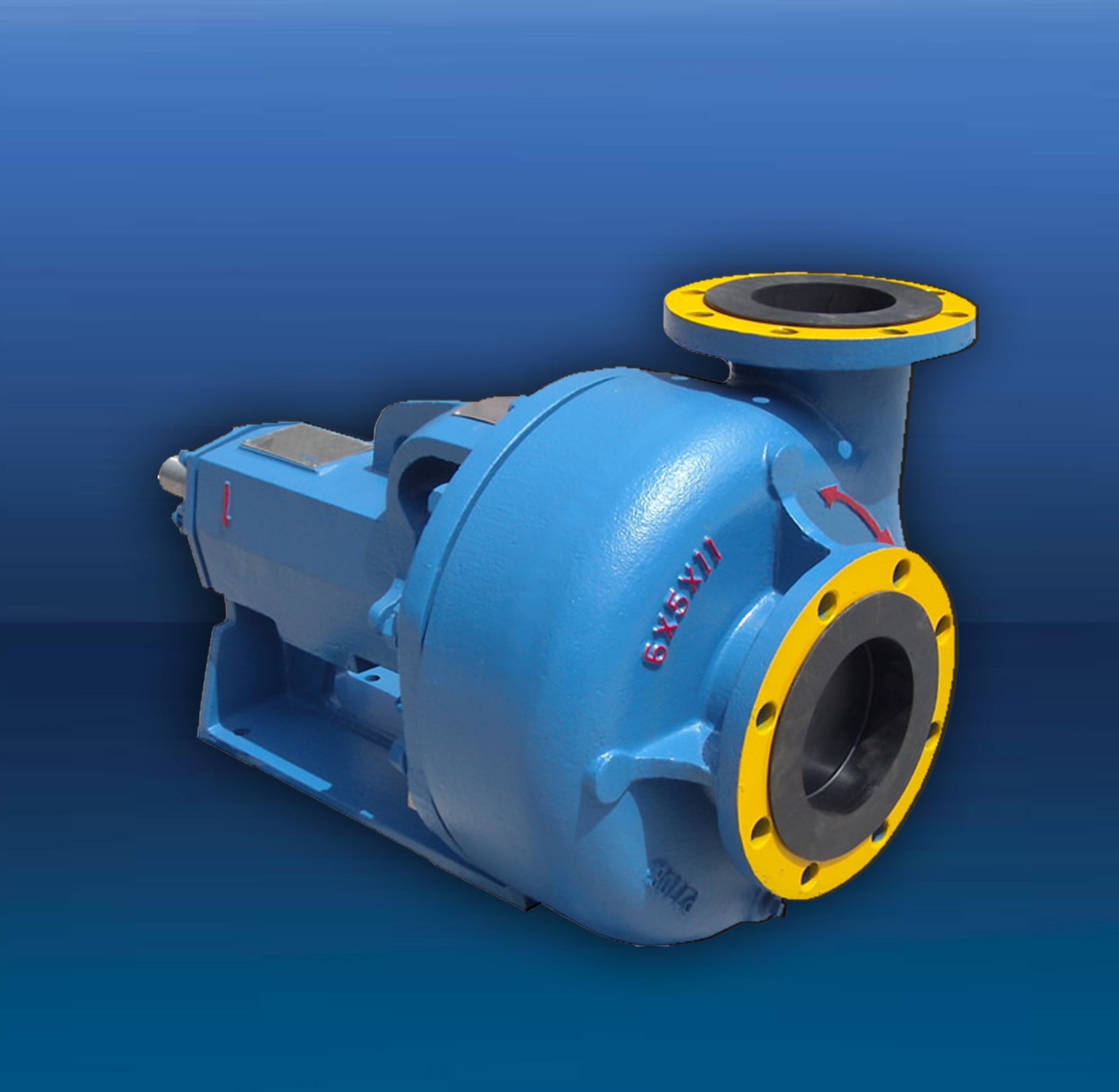
A mud pump (sometimes referred to as a mud drilling pump or drilling mud pump), is a reciprocating piston/plunger pump designed to circulate drilling fluid under high pressure (up to 7,500 psi or 52,000 kPa) down the drill string and back up the annulus. A mud pump is an important part of the equipment used for oil well drilling.
Mud pumps can be divided into single-acting pump and double-acting pump according to the completion times of the suction and drainage acting in one cycle of the piston"s reciprocating motion.
Mud pumps come in a variety of sizes and configurations but for the typical petroleum drilling rig, the triplex (three piston/plunger) mud pump is used. Duplex mud pumps (two piston/plungers) have generally been replaced by the triplex pump, but are still common in developing countries. Two later developments are the hex pump with six vertical pistons/plungers, and various quintuplexes with five horizontal piston/plungers. The advantages that these new pumps have over convention triplex pumps is a lower mud noise which assists with better measurement while drilling (MWD) and logging while drilling (LWD) decoding.
The fluid end produces the pumping process with valves, pistons, and liners. Because these components are high-wear items, modern pumps are designed to allow quick replacement of these parts.
To reduce severe vibration caused by the pumping process, these pumps incorporate both a suction and discharge pulsation dampener. These are connected to the inlet and outlet of the fluid end.
The power end converts the rotation of the drive shaft to the reciprocating motion of the pistons. In most cases a crosshead crank gear is used for this.
Displacement is calculated as discharged liters per minute. It is related to the drilling hole diameter and the return speed of drilling fluid from the bottom of the hole, i.e. the larger the diameter of drilling hole, the larger the desired displacement. The return speed of drilling fluid should wash away the debris and rock powder cut by the drill from the bottom of the hole in a timely manner, and reliably carry them to the earth"s surface. When drilling geological core, the speed is generally in range of 0.4 to 1.0 m^3/min.
The pressure of the pump depends on the depth of the drilling hole, the resistance of flushing fluid (drilling fluid) through the channel, as well as the nature of the conveying drilling fluid. The deeper the drilling hole and the greater the pipeline resistance, the higher the pressure needed.
With the changes of drilling hole diameter and depth, the displacement of the pump can be adjusted accordingly. In the mud pump mechanism, the gearbox or hydraulic motor is equipped to adjust its speed and displacement. In order to accurately measure the changes in pressure and displacement, a flow meter and pressure gauge are installed in the mud pump.
The construction department should have a special maintenance worker that is responsible for the maintenance and repair of the machine. Mud pumps and other mechanical equipment should be inspected and maintained on a scheduled and timely basis to find and address problems ahead of time, in order to avoid unscheduled shutdown. The worker should attend to the size of the sediment particles; if large particles are found, the mud pump parts should be checked frequently for wear, to see if they need to be repaired or replaced. The wearing parts for mud pumps include pump casing, bearings, impeller, piston, liner, etc. Advanced anti-wear measures should be adopted to increase the service life of the wearing parts, which can reduce the investment cost of the project, and improve production efficiency. At the same time, wearing parts and other mud pump parts should be repaired rather than replaced when possible.

The report covers comprehensive information about market trends, volume (Units) and value (US$ Mn) projections, competition and recent developments and market dynamics in the global mud pumps market for the study period of 2013 to 2026.
The global mud pumps market is expected to reach a little over US$ 1,085 Mn over the forecast period, registering a CAGR of 4.4%. Growth in drilling activities in the oil & gas Industry to increase hydrocarbon production and ease of the mud circulation operation in drilling holes are some of the factors expected to lay a robust foundation for the growth of the global mud pumps market.
Mud pumps can be classified on the basis of the number of pistons into duplex, triplex and quintuplex, which consist of two, three and five pistons respectively. The triplex segment is expected to dominate the mud pumps market in terms of value as well as volume during the entire forecast period.
Triplex mud pumps find extensive usage in circulating drilling fluid with high pressure for deep oil well drilling application. These usage characteristics make them preferable for use, primarily in onshore and offshore oil well drilling applications.
By the end of 2026, the triplex segment is projected to grow 1.42X its size in 2018 by value, creating an absolute dollar opportunity of nearly US$ 234 Mn during the forecast period.
Mud pumps are widely utilized in the oil & gas industry. On the basis of the mode of operation, mud pumps can be classified as electric and fuel engine mud pumps.
Fuel engine mud pumps use petroleum oils as the key liquefying agent. These types of mud pumps release hazardous gases into the environment. In order to contain the hazardous impact of fuel engine mud pumps on the environment, regulatory authorities are compelling manufacturers and consumers to opt for electric mud pumps, which do not emit volatile organic compounds and operate with low noise and low vibration. Electric mud pumps offer smooth operations in drilling rigs and are environment-friendly, which is why they dominate the market for mud pumps.
The electric mud pumps segment is projected to grow with a 4.5% CAGR during the forecast period in view of the tightening emission control regulations and is expected to create an absolute $ opportunity worth US$ 134 Mn between 2018 and 2026.
Among all the applications analyzed in this global mud pumps market study, the onshore application of mud pumps is expected to register about 1.43X growth in terms of value between 2018 and 2026. The offshore application of mud pumps is projected to register moderate growth during the entire forecast period, led by land oil field discoveries.
In terms of incremental $ opportunity, onshore and offshore segments are expected to compete within large margins. The onshore application of mud pumps is expected to occupy over an 86% share in terms of value by the end of 2026.
Increasing oil-well exploration activities, stable economic conditions and consistent growth in oil well drilling rig sales in the region are expected to drive the demand for mud pumps in the region.
The comparatively well-established production sector in the region and increasing oil and gas industry and hydrocarbon consumption will create a healthy platform for the growth of the mud pumps market. Some regions including China and Europe are expected to gain traction in the latter half of the forecast period, owing to the anticipated growth of the oil & gas industry in these regions. North America is expected to register above-average 1.1X growth in the market. All the other regions are anticipated to exhibit moderate growth during the same period.
Apart from Europe and China, all other regions are anticipated to lose market value share over the forecast period. China and Europe are collectively expected to register a CAGR of 4.3% by value.
The global mud pumps market is consolidated with limited market players holding considerable double-digit market shares as of 2017. Globally, the top 12 players in the mud pumps market collectively hold between 53% and 58% of the market share.
Over the past few years, the mud pumps market has witnessed significant technological advancement from the competition perspective. Acquisitions, collaborations and new product launches are some of the key strategies adopted by prominent players to expand and sustain in the global mud pumps market.
In 2018, National Oil Varco signed a deal with Dubai Saudi Armaco to form a joint venture for the manufacturing of onshore rigs and equipment in Saudi Arabia
In 2015, Flowserve opened a new pump manufacturing plant in Coimbatore, India. Through this new facility, the company aims to provide pump products for the oil and gas industry in Asia Pacific
Some of the key players involved in this market study on the global mud pumps market include National Oil Varco Inc., Schlumberger Limited, Gardner Denver Inc., Weatherford International Plc., China National Petroleum Corporation, Trevi-Finanziaria Industriale S.p.A., MhWirth, BenTech GmbH Drilling Oilfield systems, American Block Inc., Honghua Group Limited, White Star Pump Company LLC, Flowserve corporation, Ohara Corporation, Mud King Products, Inc. and Herrenknecht Vertical GmbH.

A large valve, usually installed above the ram preventers, that forms a seal in the annular space between the pipe and well bore. If no pipe is present, it forms a seal on the well bore itself. See blowout preventer.†
The space around a pipe in a well bore, the outer wall of which may be the wall of either the bore hole or the casing; sometimes termed the annular space.†
One or more valves installed at the wellhead to prevent the escape of pressure either in the annular space between the casing and the drill pipe or in open hole (for example, hole with no drill pipe) during drilling or completion operations. See annular blowout preventer and ram blowout preventer.†
A blowout preventer that uses rams to seal off pressure on a hole that is with or without pipe. It is also called a ram preventer. Ram-type preventers have interchangeable ram blocks to accommodate different O.D. drill pipe, casing, or tubing.†
A heavy, flanged steel fitting connected to the first string of casing. It provides a housing for slips and packing assemblies, allows suspension of intermediate and production strings of casing, and supplies the means for the annulus to be sealed off. Also called a spool.†
A pit in the ground to provide additional height between the rig floor and the well head to accommodate the installation of blowout preventers, ratholes, mouseholes, and so forth. It also collects drainage water and other fluids for disposal.†
The arrangement of piping and special valves, called chokes, through which drilling mud is circulated when the blowout preventers are closed to control the pressures encountered during a kick.†
A centrifugal device for removing sand from drilling fluid to prevent abrasion of the pumps. It may be operated mechanically or by a fast-moving stream of fluid inside a special cone-shaped vessel, in which case it is sometimes called a hydrocyclone.†
A centrifugal device, similar to a desander, used to remove very fine particles, or silt, from drilling fluid. This keeps the amount of solids in the fluid to the lowest possible level.†
A small enclosure on the rig floor used as an office for the driller or as a storehouse for small objects. Also, any small building used as an office or for storage.†
The hoisting mechanism on a drilling rig. It is essentially a large winch that spools off or takes in the drilling line and thus raises or lowers the drill stem and bit.†
The cutting or boring element used in drilling oil and gas wells. Most bits used in rotary drilling are roller-cone bits. The bit consists of the cutting elements and the circulating element. The circulating element permits the passage of drilling fluid and uses the hydraulic force of the fluid stream to improve drilling rates.†
A heavy, thick-walled tube, usually steel, used between the drill pipe and the bit in the drill stem. It is used to put weight on the bit so that the bit can drill.†
The heavy seamless tubing used to rotate the bit and circulate the drilling fluid. Joints of pipe 30 feet long are coupled together with tool joints.†
A wire rope hoisting line, reeved on sheaves of the crown block and traveling block (in effect a block and tackle). Its primary purpose is to hoist or lower drill pipe or casing from or into a well. Also, a wire rope used to support the drilling tools.†
On diesel electric rigs, powerful diesel engines drive large electric generators. The generators produce electricity that flows through cables to electric switches and control equipment enclosed in a control cabinet or panel. Electricity is fed to electric motors via the panel.†
A large, hook-shaped device from which the elevator bails or the swivel is suspended. It is designed to carry maximum loads ranging from 100 to 650 tons and turns on bearings in its supporting housing.†
The heavy square or hexagonal steel member suspended from the swivel through the rotary table. It is connected to the topmost joint of drill pipe to turn the drill stem as the rotary table turns.†
A device fitted to the rotary table through which the kelly passes. It is the means by which the torque of the rotary table is transmitted to the kelly and to the drill stem. Also called the drive bushing.†
A portable derrick capable of being erected as a unit, as distinguished from a standard derrick, which cannot be raised to a working position as a unit.†
The derrickman"s working platform. Double board, tribble board, fourable board; a monkey board located at a height in the derrick or mast equal to two, three, or four lengths of pipe respectively.†
Shallow bores under the rig floor, usually lined with pipe, in which joints of drill pipe are temporarily suspended for later connection to the drill string.†
A series of open tanks, usually made of steel plates, through which the drilling mud is cycled to allow sand and sediments to settle out. Additives are mixed with the mud in the pit, and the fluid is temporarily stored there before being pumped back into the well. Mud pit compartments are also called shaker pits, settling pits, and suction pits, depending on their main purpose.†
A trough or pipe, placed between the surface connections at the well bore and the shale shaker. Drilling mud flows through it upon its return to the surface from the hole.†
A diesel, Liquefied Petroleum Gas (LPG), natural gas, or gasoline engine, along with a mechanical transmission and generator for producing power for the drilling rig. Newer rigs use electric generators to power electric motors on the other parts of the rig.†
A hole in the rig floor 30 to 35 feet deep, lined with casing that projects above the floor. The kelly is placed in the rathole when hoisting operations are in progress.†
Shallow bores under the rig floor, usually lined with pipe, in which joints of drill pipe are temporarily suspended for later connection to the drill string.†
A mud pit in which a supply of drilling fluid has been stored. Also, a waste pit, usually an excavated, earthen-walled pit. It may be lined with plastic to prevent soil contamination.†
The hose on a rotary drilling rig that conducts the drilling fluid from the mud pump and standpipe to the swivel and kelly; also called the mud hose or the kelly hose.†
The principal component of a rotary, or rotary machine, used to turn the drill stem and support the drilling assembly. It has a beveled gear arrangement to create the rotational motion and an opening into which bushings are fitted to drive and support the drilling assembly.
A series of trays with sieves or screens that vibrate to remove cuttings from circulating fluid in rotary drilling operations. The size of the openings in the sieve is selected to match the size of the solids in the drilling fluid and the anticipated size of cuttings. Also called a shaker.†
Wedge-shaped pieces of metal with teeth or other gripping elements that are used to prevent pipe from slipping down into the hole or to hold pipe in place. Rotary slips fit around the drill pipe and wedge against the master bushing to support the pipe. Power slips are pneumatically or hydraulically actuated devices that allow the crew to dispense with the manual handling of slips when making a connection. Packers and other down hole equipment are secured in position by slips that engage the pipe by action directed at the surface.†
A relatively short length of chain attached to the tong pull chain on the manual tongs used to make up drill pipe. The spinning chain is attached to the pull chain so that a crew member can wrap the spinning chain several times around the tool joint box of a joint of drill pipe suspended in the rotary table. After crew members stab the pin of another tool joint into the box end, one of them then grasps the end of the spinning chain and with a rapid upward motion of the wrist "throws the spinning chain"-that is, causes it to unwrap from the box and coil upward onto the body of the joint stabbed into the box. The driller then actuates the makeup cathead to pull the chain off of the pipe body, which causes the pipe to spin and thus the pin threads to spin into the box.†
A vertical pipe rising along the side of the derrick or mast. It joins the discharge line leading from the mud pump to the rotary hose and through which mud is pumped going into the hole.†
A rotary tool that is hung from the rotary hook and traveling block to suspend and permit free rotation of the drill stem. It also provides a connection for the rotary hose and a passageway for the flow of drilling fluid into the drill stem.†
The large wrenches used for turning when making up or breaking out drill pipe, casing, tubing, or other pipe; variously called casing tongs, rotary tongs, and so forth according to the specific use. Power tongs are pneumatically or hydraulically operated tools that spin the pipe up and, in some instances, apply the final makeup torque.†
The top drive rotates the drill string end bit without the use of a kelly and rotary table. The top drive is operated from a control console on the rig floor.†

This invention relates to the circulation of fluid between the surface of a subterranean well and the bore hole and more specifically relates to the simultaneous control of drilling fluid circulation or mud pumps and a choke communicating with the pump.
Conventional apparatus used in rotary drilling operations includes a drilling fluid circulation pump or mud pump used to circulate drilling fluids from the surface through the well bore. These fluids are used to remove cuttings made by a rotary drill. In normal drilling fluid or mud circulation, the drilling fluid is pumped down through the drill pipe, discharged through the bit and returns to the surface in the annular space outside the drill pipe and inside the drill hole and casing placed in the well. The rate of drilling fluid circulation is determined by the necessary upward flow velocity required for removing cavings and drill cuttings from the hole and by the jetting requirements of the bit. The inherent advantage of the rotary system of drilling is that a fluid is circulated for the purpose of removing drill cuttings and maintaining a hole in such condition that the drill string can be withdrawn readily and returned to the bottom whenever necessary.
During conventional drilling it is not uncommon to encounter a sudden pressure increase or kick caused by the release of downhole liquids or gases under pressure which can affect drilling fluid circulation. When a kick is encountered, it can be necessary to vary the rate at which drilling fluid is injected into the well or to change the weight of the drilling fluid. A choke, in communication with the pump, is used to prevent significant pressure changes in conjunction with a change in the speed of operation of the mud pumps. For example, a significant increase in downhole pressure occurring as a result of an increase in the drilling fluid circulation can conceivably fracture the producing formation causing serious damage.
In normal drilling operations, the mud pumps are controlled by the driller, using a driller"s console located at the driller"s station on a rig to monitor relevant drilling parameters, including the speed of the mud pumps. Furthermore, conventional well control circulation operations also require manipulation of the choke to regulate or control the fluid pressure, especially during changes in the speed of the mud pump. On a conventional drilling rig, the choke is normally controlled from a choke console, which can be positioned on the drilling floor, at a position remote from the normal location of a driller"s console on a surface rig. Simultaneous control of both the mud pumps and the choke requires communication between the driller and one manning the choke console. Such communication is difficult, especially on engine driven drilling rigs. The noise and the use of different types of gauges on a rig cause confusion and makes such communication difficult, especially on engine driven drilling rigs. Furthermore, a more accurate gauge for pump strokes rate is conventionally located at the choke console, but conventional apparatus provide no means for using this more accurate gauge at the choke console to control the pumps. In a crisis situation, where the drilling crew is attempting to control the well, increased emphasis is placed on efficient communication and operation, which is difficult using prior art devices.
Apparatus for controlling the circulation of well control or kill fluid in a subterranean well includes a pump and a choke communicating with the pump to deliver drilling fluids from the surface of the well into the bore hole and return to the fluid handling equipment. Apparatus for monitoring the condition of the pump is normally employed at the driller"s console on the drilling rig and such pump monitoring apparatus includes a conventional pump control for regulating the speed and operation of the drilling fluid pumps. These pump controls can consist of pneumatic control valves or rheostats.
While control of the pump can be effected from the driller"s console, control of the choke can be simultaneously effected using a choke control apparatus located at a choke console, normally located on the drilling floor at a location remote from the driller"s console. A second pump control apparatus, again consisting of a conventional device, such as a pneumatic control valve or a rheostat, is located at the choke monitoring console and can be used to regulate pump speed and operation in the same manner as the first pump control apparatus located at the driller"s console. Apparatus is provided for overriding the first pump control upon transmission of a signal from the second pump control. Such apparatus can comprise a pneumatic valve unit or an electrical relay consisting of normally closed and normally open switches which change state upon actuation of the second pump control apparatus. In the preferred embodiment of this invention, the overriding signal is the same as the pump control signal. When this pump control signal is transmitted, a valve or relay functions to override the first pump control apparatus. Signals transmitted from the second pump control located at the choke console can then be transmitted to the pumps.
In the preferred embodiment of this invention, the overriding apparatus comprises a portion of an interface network located in the driller"s console, and the second pump control signal is transmitted from the choke console through the driller"s console and subsequently to the drilling fluid or mud pumps. In this manner, control of both the pump and the choke can be transferred to the same location on the drilling rig to provide for better control over both the rate of circulation of the drilling fluids and over the pressure maintained in the bore hole. Such centralized control is quite useful in certain situations, such as when a kick is encountered.
The preferred embodiments of the invention depicted herein are intended for use with conventional driller"s consoles and choke consoles employed on diesel or electrically powered rigs commonly used for drilling subterranean wells. The interface network and remote pump control apparatus employed in the choke console are consistent with conventional commercially available components of driller"s consoles and choke console.
FIG. 1 shows the conventional location of the driller"s console 2 and choke console 4 between which signals are transmitted to regulate or control both mud pumps 6 and the choke 8. The choke console 4 located proximate to the choke 8 separately controls the operation of the choke. The driller"s console 2 includes means for separately controlling the mud pumps 6 and signals may be transmitted from the choke console to the driller"s console for regulating the operation and speed of the mud pump. It can be seen from FIG. 2 that in the preferred embodiment of this invention the choke console controls the pumps by signals transmitted through the driller"s console 2. The transmission of signals between the various components shown in FIG. 2 can be by any of a number of conventional means, such as by electrical signals, by pneumatic or hydraulic signals, by fiber optic signals, by power line modulation, or in any other conventional form suitable for use on a drilling rig. A pneumatic control network for use with a diesel powered rig and an electrical interface network for use within an electrically powered drilling rig will be described herein.
FIGS. 3-5 depict the operation of a pneumatic interface network for a diesel powered rig. Only those portions of the pump control and the interface network relevant to the control of drilling fluid, circulating or mud pumps are depicted. Numerous other components are employed in a driller"s console or in a choke console. Such components are, however, conventional and the components shown in FIG. 3 are compatible with other conventional components controlling the operation of a drilling rig. The pneumatic interface network for the diesel powered rig shown in FIG. 3 is intended for use in controlling two mud pumps. On conventional drilling rigs, two or more mud pumps are employed, although it is common practice to use only a single mud pump at a time, retaining the other mud pumps for redundancy and/or for emergency situations. The two pneumatic control valves 12 and 26 contained within the driller"s console comprise conventional valves commonly employed in driller"s console. Valves manufactured by American Standard having a pressure range of 0 to 100 psi for clutch and throttle signals represent one conventional valve for controlling the mud pump. A plurality of shuttle valves 18, 20, 32 and 34, each comprising a dual input-single output valve, are employed on opposite sides of each of the first or main pneumatic control valves 12 and 26 for controlling the operation of the mud pumps. Shuttle valves 18, 20, 32 and 34 may comprise conventional valves, such as the P-54350-2 shuttle valve manufactured by Wabco, an American Standard Company. Of course other similar valves could be used to form the isolation function of these shuttle valves. Valve 70, also located at the driller"s console, comprises a four element stack valve unit consisting of valve elements 70a, 70b, 70c and 70d. Pneumatic valves 70 each comprise spring loaded, dual input, single output valves forming a valve stack 70. Individual valves are of conventional construction and comprise valves such as the A222PS valves manufactured by ARO Inc. which can be secured together by using an MKN stacking kit and an isolator plate manufactured by ARO Inc.
The pneumatic control valve 46 employed in the choke console comprises, in the preferred embodiment of this invention, an HD-2-FX pneumatic control valve having a pressure range from 0 to 100 psi, manufactured by American Standard. Pneumatic control valve 46 has a single input and three separate outputs. Valve 46 is located in the choke console and communicates with a conduit 40 providing air under pressure for use in actuating the various components depicted herein. A toggle switch 42 and an indicator light 44 are located on the choke console to insure that control is not transferred between the choke console and the driller"s console at a time when the differences in the throttle settings between the choke console and the driller"s console will create a serious pressure increase below the well, thus damaging the formation.
Three conduits 48, 50 and 52 extend from pneumatic control valve 46 to the driller"s console. Conduits 50 and 52 comprise the clutch C1 and clutch C2 signal paths for controlling the chokes 8 and communicate between the pneumatic control valve 46 and the individual valve units of stack valve 70. Clutch C1 line 52 is interconnected to shuttle valve element 20 and clutch C2 transmission line 50 is interconnected to shuttle valve 32. A T-conduit 54 is interconnected to the clutch C1 line 52 intermediate its ends and the T-conduit 54 establishes fluid communication between the clutch C1 line 52 and the first valve unit 70a. A separate branch 56 establishes communication between T-conduit 54 and another unit 70d of the stack. Each of the stack valves 70a-70d comprises a normally spring loaded valve in which the input from either rig air conduit 64 or from throttle valve line 48 passes directly through valve units 70a-70d. The T-conduit 54 and its adjoining conduit 56 lead from clutch line 52 and communicate with an actuator port on valve units 70a and 70d. Fluid pressure in conduit 54 and 56 serves to shift the pneumatic valve units 70a and 70d to close lines 64 or 48 when pressure is applied to clutch C1 conduit 52.
The clutch C2 line 50 extends the pneumatic control valve 46 into the driller"s console and communicates with shuttle valve 32. A T-conduit section 58 and branch 60 communicate with clutch C2 line 50 and with the remaining two valve units 70b and 70c at the actuator ports thereof. Pressure in clutch C2 line 50 will cause the valve units 70b and 70c to close against the action of a spring similarly disrupting the input from conduit 64 or 48 respectively.
The rig air input from conduit 64 into stack valve units 70a and 70b passes through lines 66 and 68 respectively to the pump control valves 12 and 26 when stack valves 70a and 70b are in the open position. Essentially, the stack valve units 70a and 70b are connected in parallel to the rig air source 64. The output conduits 61 and 62 leading from the stack valve units 70c and 70d are respectively connected to shuttle valves 18 and 34. Communication is normally established between throttle line 48 and valves 18 and 34 through the stack valve units 70c and 70d when the spring loaded valves are in their normally open position.
The first pneumatic control valves 12 and 26 comprise conventional elements for generating clutch and throttle signals in response to a constant pressure supply or rig air in conduit 64. For example, valve 12 generates a clutch signal in line 14 and a throttle signal in line 16. Clutch line 14 communicates with one of the two input ports of shuttle valve 20. Throttle line 16 communicates with one of the two input ports of shuttle valve 18.
FIG. 3 depicts a condition in which the mud pumps 6 and 6" can be controlled by using the first or primary mud pump controllers 12 and 26. It should be understood that in an actual practice, only one pump is normally used. Solid lines have been used to indicate that pneumatic signals communicate through the line, while dashed lines indicate that the line has been disabled and no signal is transmitted. As shown by the solid lines in FIG. 3, pressure in line 64, which is obtained from a source of rig air, communicates through the normally open stack valves 70a and 70b to lines 66 and 68 respectively. Rig air is then applied to pneumatic control valves 12 and 26. Referring to control valve 12, the presence of rig air at the input of this first control valve permits clutch and throttle signals to be generated in lines 14 and 16 respectively. Since the choke console pneumatic control valve is in the off position, as shown in FIG. 3, and there is no pressure in lines 48, 50 and 52, a pneumatic signal is applied in only one of the dual input ports of shuttle valves 18 and 20. A pneumatic clutch signal in line 14 can be transmitted through shuttle valve 20 and clutch line 22 directly to the drilling fluid or mud pump. Similarly, a throttle signal in line 16 would be transmitted through shuttle valve 18 and line 24 to the pump. Thus the pneumatic throttle and clutch signals to pump 6 are employed to control the operating speed of an internal combustion engine, for example, driving pump 6 and an operating clutch to engage or disengage the pump as desired or required.
FIG. 4 shows the condition in which the choke console pneumatic control valve 46 is actuated to apply a pneumatic signal in clutch line 52 and in throttle line 48. Pneumatic control valve 46 is of the type that actuation of a control lever in one direction will induce a clutch signal during initial movement and thereafter will produce a throttle signal. The pneumatic signal in clutch line 52 acts through lines 54 and 56 on the actuator ports of stack valve units 70a and 70d. Pressure applied at the actuator ports plugs the input lines to stack valve units 70a and 70d. Thus the rig air from line 64 is plugged by stack valve unit 70a thus disabling the first mud pump control valve 12 which comprises the primary means of regulating the mud pump 6 from the driller"s console. The pneumatic signal in line 52 is, however, transmitted to the second input port of shuttle valve 20. Since there is no pressure in line 14, any clutch signal in line 52 at shuttle valve 20 will be transmitted through line 22. The pneumatic signal in line 52 communicating with line 56 also disables the throttle input to stack valve unit 70d isolating shuttle valve 34 from the throttle line 48. Stack valve unit 70c, however, remains open and the pneumatic signal in throttle line 48 will be transmitted through line 61 to shuttle valve 18. This pneumatic signal in line 61 is in turn transmitted through throttle line 24 to the first mud pump. Similarly, the stack valve unit 70b remains open and rig air from co


 8613371530291