
mud pump valve body insert quotation
A wide variety of mud pump valve inserts options are available to you, such as 1 year, not available.You can also choose from new, mud pump valve inserts,As well as from energy & mining, construction works , and machinery repair shops. and whether mud pump valve inserts is 1.5 years, 6 months, or 3 months.

A wide variety of mud pump insert valve options are available to you, such as 1 year, not available.You can also choose from new, mud pump insert valve,As well as from energy & mining, construction works , and machinery repair shops. and whether mud pump insert valve is 1.5 years, 6 months, or 3 months.

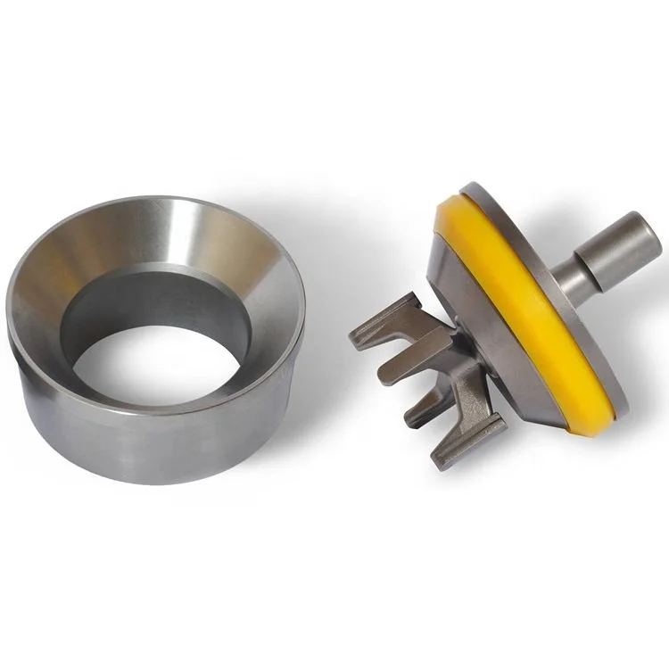
Mud Pump Valve & Seat are made of premium alloy steel through one-piece forging and carburizing treatment processes, thereby ensuring high intensity. In addition, the precise calculation is performed and CNC machining is conducted for the dimensional matching of the valve seat and valve body working angles to enhance the service life of the valve body and valve seat. Our valve products are able to work smoothly in normal mining and digging conditions for over 400 hours.

Delian valve and seat are made of forged alloy steel with deep carburized wear surface. We offer a full range of valves and seats which include full open valve and seat, 3 web / 4 web design valve and seat.
The valve comes with full open seat features four guide wings. They are either inertia welded to the valve body or uniformly forged with valve body. The urethane insert can be easily snapped on.

Also known as Nova Tech Valve or Roughneck Valve or High Pressure Valve. Full open Seat & wing guided Valve design features a large metal-to-metal bearing area for long life, directly casted urethane insert on valve body results in a perfect round shape that prevents premature failures of the insert. The insert is casted around the serrations, thus failure due to tears from the serrations are eliminated Most importantly the insert is not stretched over the valve during installation; there are no residual stresses left, to shorten insert life.
Urethane bonded insert offers increased resistance to water , synthetic and oil based drilling fluids and is capable of operating in fluid temperatures of up to 220˚F (104˚C) while maintaining superior resistance to tear and extrusion

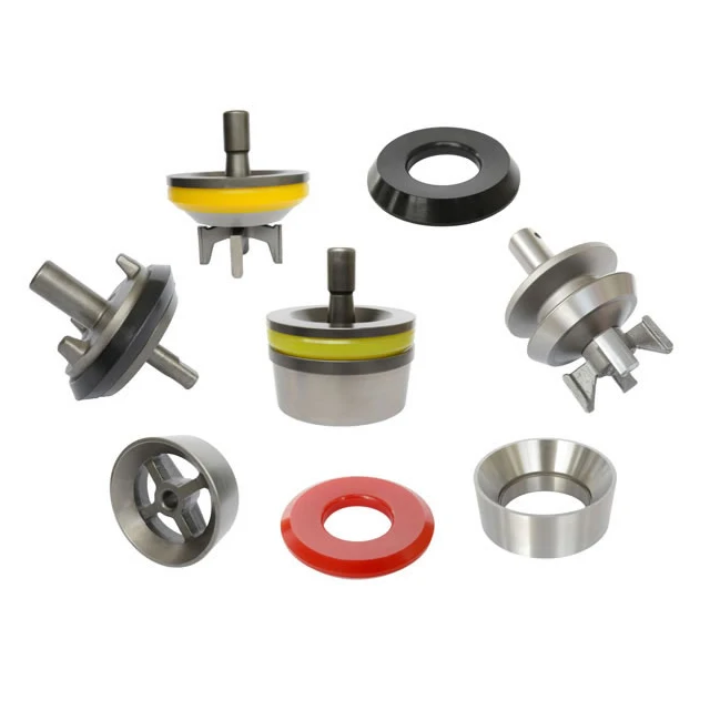
We can supply many kinds of mud pump spare parts to fit your drilling needs, suiting to almost all popular mud pumps in the world.. Such as valve, valve seats, liner, piston, fluid end parts, crankshaft Assembly, Pinionshaft assembly, valve cover, liner cage, liner nut, valve seat puller, extension rod and piston rod, bearing, cylinder etc.
4.The rubber sheet is made of polyurethane material which improves the service life of valve assembly, the operational use time is more than 300 hours.
The invention related to drilling fluid or “mud” systems; to relief valves for such systems; and to apparatus, systems and methods for relieving fluid pressure in pressurized devices or systems.
In certain typical wellbore drilling situations using a drilling rig, drilling fluid or “mud” is pumped by a pumping system with one or more “mud” pumps (e.g. some systems have a triplex mud pump). The mud pump system delivers a large volume of mud flow under pressure for operations of the drilling rig. The mud is delivered to the drill stem to flow down the string of drill pipe and out through the drill bit appended to the lower end of the drill stem. It flows through the drill bit. The flow of mud cools the drill bit and reduces the temperature so that it lasts longer. Also, in certain situations, the mud flow is jetted out through a set of openings in the drill bit so that the mud hydraulically washes away the face of the well borehole if it is formed of soft materials. In addition, it washes away debris, rock chips and cuttings which are generated as the drill bit advances. Then, the mud flow returns to the surface in an annular space on the outside of the drill stem and on the interior of the open hole formed by the drilling process. While portions of the borehole may be cased from the surface, is of sufficient velocity that the mud is returned to the surface so that debris, chips and cuttings which are heavier than the mud are moved to the surface. This requires a substantial flow velocity. The cooling necessary also requires a substantial velocity. A relatively high volume of mud is needed to achieve these flow velocities. Typical mud pump systems can deliver 500 to 1,000 gallons per minute through the drill stem. The flow of mud must be delivered under control. The mud pump system can be required to deliver mud flow at 1,000 psi and higher. The wellhead pressures at the pump must be much higher if there is substantial flow pressure resistance along the flow path. The pump therefore is often operated at a very high pressure. The drill stem in a deep well is an impediment to flow, thereby resulting in higher back pressures. The impediment to flow is overcome by applying greater pressures at the surface. In this regard, the mud pump system can typically be operated at pressures as high as 5,000 psi output. Because of the great variety of circumstances in which the drilling rig may be used, the output pressure of the mud pump may vary widely. In one aspect, the mud pump output pressure varies with the change in pump speed. Mud pumps can operate with pressure peaks that can be excursions as great as 200 or 300 psi on top of the prevailing baseline pressure. Thus mud pump output pressure can vary significantly.
The prior art discloses a variety of mud systems, relief valves and regulators, and systems to control and stabilize the pressure downstream of mud pump systems; see, for example, and not by way of limitation, U.S. Pat. Nos. 5,063,776; 5,616,009; 5,975,129; 7,055,623; 5,715,861; 4,638,978; and in U.S. application Ser. No. 11/098,166 filed Apr. 4, 2005 (co-owned with the present invention), all incorporated fully herein for all purposes. In many prior art systems, a mud pump output manifold is input to a pressure relief valve which is operated so that the output pressure is controlled to a desired level, thus allowing a mud pump system to operate with a controlled pressure level to insure that the pressure experienced down hole at the drill bit and in the formations penetrated by the drill bit is regulated and to protect the mud pump system itself.
Various operations involve the use of pressurized systems and/or devices. For example, many different components used in the petroleum drilling and production industries, such as fluid pumps and mud pumps, are used in pressurized systems and subject to potentially significant internal fluid pressures. It is often desirable or necessary to relieve these systems and devices from excessive pressure to prevent equipment damage and failure, personal injury or for other reasons. To assist in relieving undesirable fluid pressure in pressurized systems and devices, pressure relief technology is commonly used.
Currently available versions of pressure relief valves, systems and methods have various disadvantages. For example, many pressure relief valves wear and fail quickly due to high pressure fluid passing therethrough. For another example, various versions of pressure relief valves are large and bulky and require extensive space for operation. For still another example, many pressure relief valves are difficult to disassemble for servicing and maintenance. For an even further example, some pressure relief valves throttle between open and closed positions during operation, which is undesirable in many applications. For still another example, some pressure relief valves are purely mechanical in operation, which may contribute to inaccurate valve operation and overall poor or erratic performance. There are yet other potential disadvantages of presently available pressure relief valves, systems and methods. It should be understood, however, that each embodiment of the present invention and each claim of this patent does not necessarily address or solve every, or any particular, disadvantage of the existing technology.
Thus, there remains a need for pressure relief valve assemblies, systems and methods having one or more of the following attributes, capabilities or features: may be easily disassembled and reassembled; is easy to inspect and service, adjust and/or repair in the field; allows for the repair and replacement of internal valve components without removing the valve body from the line or equipment to which it is attached; has reduced likelihood of damage to internal valve components when discharging fluids; is not difficult to manufacture; includes a valve that is easily opened to allow access for inspection or removal of internal components; includes a valve having an angle-body configuration and/or a fluid flow path with approximately a ninety degree turn; includes a valve having a “flow-to-close” and/or a “fail-to-open” arrangement; includes a valve that opens rapidly and resets easily; includes a snap or pop acting valve; includes a valve having increased longevity; includes a valve that does not throttle between open and closed positions so that when the fluid pressure in the pressurized device is too high, the valve stays fully open until closed; includes a valve actuator that is integral to the valve; includes a reciprocating valve actuator stem or piston that does not protrude from the valve assembly; includes a valve actuator that is electronically controllable; includes an actuator piston engaged with and moveable on the same axis as the valve piston; includes an actuator piston actuated based upon the actual measured pressure of fluid in the pressurized device or system; includes a solenoid valve useful to assist in controlling movement of an actuator piston; includes a valve piston and/or actuator piston that is mechanically-biased in one direction; includes a valve piston and/or actuator piston that is controllably movable in one direction by fluid pressure; includes a valve piston and/or actuator piston that is internally sealed without metal seating; or any combination thereof. BRIEF SUMMARY OF THE PRESENT INVENTION
The present invention, in certain embodiments, discloses pressure relief valve assemblies useful for relieving fluid pressure in a pressurized device (e.g., but not limited to, mud pump systems with at least one mud pump), the pressure relief valve assemblies having: a valve body with an inlet passageway in fluid communication with an outlet passageway; a valve member within the valve body for selectively controlling fluid flow from the inlet passageway to the outlet passageway, the valve member having a first end and a second end, the outlet passageway having an entrance end and an exit end; the first end of the valve member movable into the outlet passageway to prevent fluid flow from the inlet passageway through the outlet passageway; a wear member around a portion of the entrance end of the outlet passageway; the wear member having an interior surface; the valve member movable within and sealingly contacting the interior surface of the wear member; the outlet passageway having a length, the wear member extending into the outlet passageway a distance less than the length of the outlet passageway; the valve body having an interiorly threaded portion at the entrance of the outlet passageway; the wear member having an exteriorly threaded portion; and the wear member releasably secured to the valve body by threaded engagement of the wear member"s exteriorly threaded portion with the valve body"s interiorly threaded portion.
Various embodiments of the present invention involve a pressure relief valve assembly useful for relieving fluid pressure in a pressurized device. The pressure relief valve assembly, in certain aspects, includes an angle-body valve having a valve piston disposed therein and being movable between at least one closed position and at least one open position. The closed position of the valve piston prevents fluid flow through the valve from the pressurized device and the open position allows fluid flow through the valve from the pressurized device.
An actuator according to certain aspects of the present invention is capable of moving the valve piston between closed and opened positions. The actuator includes an actuator piston that is fluid-powered in at least one direction. When the actuator piston is fluid-powered in only one direction, it is mechanically-biased in the opposite direction. The actuator piston is connected with, and movable along the same axis as, the valve piston. The actuator piston is moveable between at least one extended position and at least one retracted position. The valve piston is in a closed position when the actuator piston is in an extended position and the valve piston is in an open position when the actuator piston is in a retracted position. A remotely-operated directional control valve is associated with the actuator and useful for directing fluid power to allow the actuator piston to move from an extended position to a retracted position, causing the valve piston to move from a closed position to an open position.
At least one electronic pressure measuring device is separate from and associated with certain embodiments of the remotely-operated directional control valve and monitors pressure within the pressurized device. The position of the remotely-operated directional control valve is varied based upon power supplied to the control valve that is based upon at least one reading taken by the electronic pressure measuring device.
In some embodiments, a pressure relief valve assembly useful for relieving fluid pressure in a pressurized device includes an unintelligent angle-body valve having a flow-to-close arrangement. The valve includes a valve piston capable of moving between open and closed positions. The valve piston in the open position allows venting of fluid from the pressurized device through the valve. Movement of the valve piston into an open position does not depend upon internal fluid pressure within the unintelligent angle-body valve. At least one electronic pressure measuring device is capable of monitoring pressure within the pressurized device. An electronic controller is capable of causing the opening and closing of the valve piston based upon pressure readings of the electronic pressure measuring device.
Accordingly, the present invention includes features and advantages which are believed to enable it to advance pressure relief valve technology. Characteristics and advantages of the present invention described above and additional features and benefits will be readily apparent to those skilled in the art upon consideration of the following detailed description of preferred embodiments and referring to the accompanying drawings.
Referring to FIG. 1, a system S according to the present invention includes a mud system M with mud pits 28 for containing and storing drilling fluid; mud pumps 16 for pumping the drilling fluid to drillstring 18 and back to the mud pits 28; and a relief valve 8 according to the present invention for relieving pressure in the system. The drilling fluid or “mud” flows down the drill string 18 and then up in an annulus 20 between casing 22 and the drill string 18 to a bell nipple 24. The mud then flows in a return line 26 to the mud pits 18.
Initially mud flows into the valve 8 through a line 21 that is in communication with the line 19. A pressure sensor 23 senses a signal indicative of the pressure in the line 19, via the line 21, to a control system 14 which controls operation of the valve 8 and controls an air supply 12 which provides air under pressure to maintain the valve 8 closed until a pre-selected mud pressure is exceeded. When the mud pressure exceeds the pre-selected pressure, the valve 10 opens and the mud that was previously flowing to the drill stem 18 flows through the inlet 13 of the valve 8 and exits through an outlet 15 into an exit line 17. When pressure in the line 19 again falls below the pre-selected pressure, the control system 14 signals the air supply 12 to close the valve 8 (as will be described in more detail for certain embodiments described below).
FIG. 2 shows schematically the mud flow path for the system M. As shown in FIG. 2, the system M (like numerals indicate like parts) includes a degasser 25 which reduces the gas content of the mud. In certain aspects, the control system (“CONTROLLER”) includes an automatic reset function and also permits manual resetting (“ReSet,” FIG. 2), e.g. to re-close the valve after it has relieved pressure; and/or the possibility of two settings (“Hi,” “Low,” FIG. 2) corresponding to two different pressure setpoints (e.g. a high setting, e.g. 7500 psi, at which the valve opens for relief and a low setting, e.g. below 400 psi). The valve is operable by manually pressing an “Operate” button. The controller can be a computerized system and/or PLC appropriately programmed.
Referring now to FIGS. 3A-3C, a relief valve 100 (one embodiment of the relief valve 8, FIG. 1) includes a valve 120 and an actuator 160. In the embodiment shown, the valve 120 is an angle-body, two-way valve that includes a valve body 126 having intersecting first and second passageways 130, 140. The first passageway 130 is in fluid communication with a pressurized device (not shown) (e.g. a mud pump or pumps) and allows fluid flow (arrow 131) into the valve body 126 from the pressurized device. The second passageway 140 extends to an exit port 144, allowing the exhaust (arrow 146) of fluid from the valve body 126. In an “angle-body” valve, the axis of the first passageway 130 is not concentric or coaxial with, but is approximately in the same plane as, the axis of the second passageway 140. Nuts 132 aare used on valve body studs 132 b; and nuts 142 aare used on valve body studs 142 b.
A valve piston 148 is disposed at least partially within the second passageway 140 and serves to selectively control the flow of fluid from the first passageway 130 into the second passageway 140. The valve piston 148 is movable between “open” and “closed” positions relative to the first passageway 130. In a “closed” position, such as shown in FIGS. 3A and 3B, the exemplary valve piston 148 blocks the first passageway 130, preventing fluid flow from the first passageway 130 into the second passageway 140. When the valve piston 148 is in an “open” position, the first and second passageways 130, 140 are in fluid communication, allowing the flow of fluid from the first passageway 130 (and pressurized device) into the second passageway 140 (and out the exit port 144). The valve 120 of the illustrated embodiment has a “flow-to-close” arrangement in which fluid flows through the second passageway 140 in the same direction as the movement made by the valve piston 148 going to its closed position.
The valve piston 148 has a removable cap 153 which is threadedly connected to an end of the valve piston 148. Optionally the cap 153 has an inclined or bevelled end surface 151 with holes 154 for facilitating piston installation. An exterior surface 157 of the cap 153 abuts an interior surface 121 of a seal insert 128.
The seal insert 128 (or, in one aspect a “wear member”) is threadedly and removably secured in the body 126. In one particular aspect, the seal insert 128 is made of Inconel material due to the high wear area at the beginning of the passageway 140 at which the seal insert 128 is located. In certain aspects, the seal insert"s length is considerably less than the length of the passageway 140 and, in one particular aspect, less than half said length.
The valve piston 148 has an edge 147. The seal insert 128 is sized with a sufficient length to encounter the initial highly abrasive flow of fluid at high speed from the passageway 130 to the passageway 140. Once this fluid exits the seal insert 128 it slows sufficiently so that the remainder of the interior of the passageway 140 (not protected by the seal insert 128) is not seriously worn or damaged. A seal 149 seals a valve-piston-148/actuator-housing-164 interface.
By unbolting the actuator 160 (by removing bolts 169) from the valve body 126, and removing valve piston 148 with its cap 153 from the passageway 140, the seal insert 128 can be removed from the valve body 126 for repair or replacement.
A seal 122 in a recess 157 seals a seal-insert 128/valve-body-126 interface. Holes 123 facilitate installation of the seal insert 128. Holes 152 in a cap 139 facilitate installation of the cap 139.
The actuator housing 164 has a central cavity 170 within which an actuator piston 174 is moveable. The exemplary central cavity 170 is aligned with the second passageway 140 of the valve body 26. The actuator piston 174 connects to the valve piston 148 and moves it between open and closed positions. In the example shown, an actuator stem 180 connects the actuator piston 174 with a valve stem 150 extending from the valve piston 148, all of which move on the same axis. The cap 139 is threadedly secured around the valve stem 150.
The actuator stem 180 and valve stem 150 are releasably connected together with a releasable latch pin 156 to allow quick disconnection and replacement of the valve piston 148 without disturbing the actuator 160. The illustrated latch pin 156 extends through an opening 158 in the actuator housing 164 to allow for unencumbered movement of the latch pin 156 concurrent with reciprocation of the stems 150, 180.
The actuator piston 174 may be actuated in any desired manner. In the embodiment shown in FIG. 3A, the actuator piston 174 is single acting, being fluid-powered in one direction (e.g. by pneumatic or hydraulic pressure) and mechanically-biased in the opposite direction. In one aspect when the pressurized device is a mud pump or pumps, the power fluid is air, e.g. air supplied by a rig air supply. For example, air or pneumatic pressure may be provided from an external source (not shown) into an outer portion 172 of the central cavity 170 of the actuator housing 164 to act upon an outer side 178 of the actuator piston 174 and move and hold the actuator piston 174 in an “extended” position and the valve piston 148 in a closed position (e.g. FIG. 3A). In the illustrated embodiment, in one normal operating state of the valve assembly 100 has the actuator piston 174 in an extended position and the valve piston 148 in a closed position.
The mechanical-biasing force on the actuator piston 174 (and effectively on the valve piston 148), when included, may be provided in any suitable manner. For example, one or more spring element or spring-like devices may be used to provide the sufficient biasing forces on the actuator piston 174 and move and hold the actuator piston 174 in a retracted position and the valve piston 148 in an open position, regardless of the system pressure or fluid pressure in the valve assembly 100.
In the embodiment of FIG. 3A, for example, outer and inner nested compression springs 184, 186, respectively, are shown disposed around the actuator stem 180 in the central cavity 170. The springs 184, 186 act on the inner side 176 of the actuator piston 174 to move and hold the actuator piston 174 in a “retracted” position (and the valve piston 148 in an open position). The use of dual nested springs may be included, for example, to provide adequate biasing forces in the small area of the central cavity 170 sufficient to move the actuator piston 174 and the valve piston 148. In the embodiment shown, the springs 184, 186 provide sufficient biasing force to overcome multiple sealing engagements, such as at the seals 134 and 149. However, the present invention is not limited to fluid-powering in only one direction, the use of mechanical-biasing forces or the use of one or more spring element to provide mechanical-biasing force on the actuator piston and/or the valve piston.
In another independent aspect of the invention, the actuator 160 may be controlled to move the valve piston 148 between open and closed positions in any desired manner. For example, referring to FIG. 3A, the actuator 160 may be controlled based upon the fluid pressure within, or coming from, the pressurized device (not shown), referred to herein and throughout this patent as the “relevant pressure.” Such a control scheme is referred to herein and throughout this patent as a “pressure-based” system. For example, when the valve assembly 100 of FIG. 3A is used with a fluid pump, the relevant pressure may be the upstream pressure of fluid flow into the first passageway 130 of the valve body 126 from the fluid pump. When the relevant pressure is at an acceptable or desirable value (or range), the actuator 160 retains the valve piston 148 in a closed position, not relieving pressure from the fluid pump. If the relevant pressure increases to a certain level or range, the actuator 160 is triggered to move the valve piston 148 to an open position, allowing fluid pressure relief for the fluid pump. After a certain period or, alternately, when the relevant pressure returns to a certain level or range, the actuator 160 of this example is adjusted to allow the valve piston 148 to move back to a closed position, and so on.
Any suitable components and techniques may be used in a pressure-based system. For example, a directional control valve may be used to control fluid power acting upon the actuator piston to allow it to move from an extended position to a retracted position. For example, referring to FIG. 3A, the directional control valve is a three-way, two position solenoid valve (not shown) used to control pneumatic or other fluid pressure in the outer portion 172 of the central cavity 170 of the actuator housing 164. The exemplary solenoid valve is connected with the actuator end cap 182 and actuated based upon the relevant pressure of the pressurize device (not shown). In the embodiment shown, the solenoid valve is maintained in a fluid-to-cylinder/exhaust-blocked position that allows pressurized fluid to the outer portion 172 of the outer cavity 170 through at least one port 166 to act upon the outer side 178 of the actuator piston 174 and move or retain the actuator piston 174 in an extended position. For example, air pressure in the outer portion 172 of the central cavity 170 may, in certain applications, be maintained at approximately 90 psig.
If the relevant pressure reaches a certain value (or range), the solenoid valve is actuated to move to a supply-fluid-blocked/cylinder-exhausted position, blocking or preventing pressurized fluid from acting upon the outer side 178 of the actuator piston 174 and allowing pressurized fluid from the outer portion 172 of the central cavity 170 to be exhausted from the actuator 160. This permits the actuator piston 174 to move into a retracted position, opening the valve piston 148. When the relevant pressure returns to a desired level or range, the solenoid valve is actuated to allow fluid back into the outer portion 172 of the central cavity 170 of the actuator 160. In the embodiment shown, the mechanical forces on the actuator piston 174 are overcome and the actuator piston 174 returns to an extended position, closing the valve piston 148.
In yet another independent aspect of the invention, the actuator 160 may be electronically controlled by an electronic control device or system, if desired, e.g. the “CONTROLLER” of FIG. 2 which may be any suitable control system, computerized system, and/or PLC, on-site or remote. In conjunction with the embodiment of FIG. 3A, a control valve according to the present invention is on-site or remotely-operated by a programmable logic controller (PLC) that receives relevant pressure readings from one or more electronic pressure measuring devices (e.g. “SENSOR,” FIG. 2). For example, the electronic pressure measuring device may be a pressure transducer that accurately measures, detects or reads fluid pressure in the pressurized device or the upstream pressure of fluid within, or proximate to, the first passageway of the valve body. If desired, the electronic pressure measuring device may either continuously or intermittently monitor such pressure. The position of the exemplary remotely-operated directional control valve is varied based upon electrical, mechanical, fluid power or a combination thereof supplied to it based upon at least one reading taken by the electronic pressure measuring device.
In operation of the illustrated embodiment used in conjunction with the valve assembly 100 of FIG. 3A, the PLC is powered by any suitable power supply and receives input indicating the relevant pressure from the electronic pressure measuring device. The PLC compares the received fluid pressure value(s) with one or more pre-programmed set point values or ranges (the “set point”). If the relevant pressure reaches the set point, the PLC closes a relay (not shown), providing electric power to the directional control valve, causing it to function to temporarily block the fluid supply, such as from a rig air source, into the central cavity outer portion and allow the fluid in the outer portion to exhaust out of the actuator through the directional control valve. The actuator piston is then allowed to move into a retracted position, opening the valve piston.
Thereafter, when the PLC detects that the relevant pressure has returned to a desired value/range, or based upon some other criteria, the PLC resets, or opens, the relay, reducing or eliminating power to the directional control valve. This causes the valve to function to allow fluid back into the outer portion of the central cavity, which moves the actuator piston back to an extended position. If desired, multiple set points may be used. In one example, a 0-8,000 p.s.i. pressure relief valve assembly 100 snaps open quickly (with minimal throttling) based upon a signal from a pressure transducer at a degree of accuracy of with 20% (±16 psig) of the set point pressure value. However, the present invention is not limited to such electronic control or the control components and techniques described above.
Referring initially to FIG. 1, an embodiment of a pressure relief valve assembly 10 in accordance with the present invention is shown. The pressure relief valve assembly 10 is capable of relieving fluid pressure in a device or system which is desired to be relieved of pressure (referred to herein and throughout this patent as a “pressurized device”). As used herein and throughout this patent, the term “fluid” means one or more gas, liquid, or a combination thereof, and may, if desired and suitable, also include material or particles, or slurries thereof. The pressurized device may, for example, include a triplex or duplex mud pump that may experience overpressure situations. In various embodiments, the valve assemblies of the present invention relieves such overpressure situations. However, the present invention is not limited to such use with mud pumps.
The present invention, therefore, in some, but not necessarily all embodiments, provides pressure relief valve assemblies useful for relieving fluid pressure in a pressurized device, the assemblies having: a valve body with an inlet passageway in fluid communication with an outlet passageway; a valve member within the valve body for selectively controlling fluid flow from the inlet passageway to the outlet passageway, the valve member having a first end and a second end, the outlet passageway having an entrance end and an exit end; the first end of the valve member movable into the outlet passageway to prevent fluid flow from the inlet passageway through the outlet passageway; a wear member around a portion of the entrance end of the outlet passageway; the wear member having an interior surface, the valve member movable within and sealingly contacting the interior surface of the wear member; the outlet passageway having a length, the wear member extending into the outlet passageway a distance less than the length of the outlet passageway; the valve body having an interiorly threaded portion at the entrance of the outlet passageway; the wear member having an exteriorly threaded portion, and the wear member releasably secured to the valve body by threaded engagement of the wear member"s exteriorly threaded portion with the valve body"s interiorly threaded portion. Such assemblies may have one or some (in any possible combination) of the following: wherein the wear member has a length which is less than half the length of the outlet passageway; an actuator connected to the second end of the valve member for selectively actuating the pressure relief valve assembly; the actuator including an actuator housing with a flange, the flange having bolt holes therethrough, the flange releasably bolted to the valve body; a first cap at the first end of the valve member, and a second cap at the second end of the valve member; a bore through the valve body, the wear member accessible through the bore for installation and removal thereof; a bore through the valve body, the wear member accessible through the bore for installation and removal thereof, the actuator having an actuator housing bolted to the valve body, part of the actuator housing projecting into the bore, the bore accessible when the actuator housing is unbolted from the valve body and the actuator is removed therefrom; a controller for selectively moving the valve member; the controller includes an automatic reset function to automatically close the pressure relief valve assembly following the pressure relief valve assembly acting to relieve pressure in a pressurized device; the controller programmable to reset at one of a plurality of different measured pressures at the inlet passageway; the controller able to reset the pressure relief valve assembly automatically; the pressure relief valve assembly is resettable manually; the fluid pressure is pressure of drilling fluid and the pressurized device includes apparatus for the flow of drilling fluid under pressure; the pressurized device includes at least one mud pump; wherein the wear member is made of INCONEL material; and/or the actuator is initially acted upon by fluid under pressure to maintain the valve member in a valve-closed position.
The present invention, therefore, provides pressure relief valve assemblies useful for relieving fluid pressure in a pressurized device, the assemblies having: a valve body with an inlet passageway in fluid communication with an outlet passageway; a valve member within the valve body for selectively controlling fluid flow from the inlet passageway to the outlet passageway, the valve member having a first end and a second end, the outlet passageway having an entrance end and an exit end; the first end of the valve member movable into the outlet passageway to prevent fluid flow from the inlet passageway through the outlet passageway; a wear member around a portion of the entrance end of the outlet passageway; the wear member having an interior surface, the valve member movable within and sealingly contacting the interior surface of the wear member; the outlet passageway having a length, the wear member extending into the outlet passageway a distance less than the length of the outlet passageway; the valve body having an interiorly threaded portion at the entrance of the outlet passageway; the wear member having an exteriorly threaded portion; the wear member releasably secured to the valve body by threaded engagement of the wear member"s exteriorly threaded portion with the valve body"s interiorly threaded portion; wherein the wear member has a length which is less than half the length of the outlet passageway; an actuator connected to the second end of the valve member for selectively actuating the pressure relief valve assembly; a bore through the valve body; the wear member accessible through the bore for installation and removal thereof; the actuator having an actuator housing bolted to the valve body, part of the actuator housing projecting into the bore; and the bore accessible when the actuator housing is unbolted from the valve body and the actuator is removed therefrom.
The present invention, therefore, provides in at least some embodiments, but not necessarily all, pressure relief valve assemblies useful for relieving fluid pressure in a pressurized device, the pressure relief valve assemblies having: a valve body with an inlet passageway in fluid communication with an outlet passageway; a valve member within the valve body for selectively controlling fluid flow from the inlet passageway to the outlet passageway, the valve member having a first end and a second end, the outlet passageway having an entrance end and an exit end; the first end of the valve member movable into the outlet passageway to prevent fluid flow from the inlet passageway through the outlet passageway; a wear member around a portion of the entrance end of the outlet passageway; an actuator connected to the second end of the valve member for selectively actuating the pressure relief valve assembly; wherein the actuator includes an actuator housing with a part, e.g., but not limited to, a flange; the part having bolt holes therethrough; and the part and therefore the housing releasably bolted to the valve body. Such an assembly may have: fluid pressure which is pressure of drilling fluid, and the pressurized device including apparatus for the flow of drilling fluid under pressure; and/or the pressurized device including at least one mud pump.

Valve Seat, Valve Body and Valve Nut are manufactured by using forged carbon steel / stainless steel as per the requirement of the users, suitably hardened grounded finished and hard-coated, wherever required. Special care is taken for dimensional matching between Valve Seat and Valve Body working angles to ensure long-life under severest of working conditions. Inserts are available in polyurethane and other polymers to suit customers"" requirement.
Valve Seat, Valve Body and Valve Nut are manufactured by using forged carbon steel / stainless steel as per the requirement of the users, suitably hardened grounded finished and hard-coated, wherever required. Special care is taken for dimensional matching between Valve Seat and Valve Body working angles to ensure long-life under severest of working conditions. Inserts are available in polyurethane and other polymers to suit customers" requirement.
Valve Assy. consisting of valve seats, valve body, valve spring & valve insert, valve guide are available for different models of pumps manufactured by BJ, Halliburton, Oil Well, OPI, Gardner Denver and others. Special care is taken for dimensional matching between valve seat and valve body working angles to ensure very high life under very severe working conditions. Valve Inserts are made out of high quality polyurethane material.
Stainless steel / alloy steel Plungers with or without hard-coating and ceramic-coating are available in different sizes for different models of plunger pumps manufactured by BJ, Halliburton, Oil Well, OPI, Gardner Denver and others. Selection of metallurgy for different applications for plunger and plunger packings are essentially the most important factor for longer working life. Trained and experienced engineers at our end are equipped well to suggest most appropriate metallurgy for a particular application. Plunger packings are made out of very strong fabric, built up in a very special pattern to ensures high quality long performing packings. Plungers and packings are available in almost all sizes starting from 1.3/8" to 6.1/2".

The frac pump valves and seats are also called valve and seat assembly. There are valve body, valve insert, valve seat, and O-ring, these four parts consist of the frac pump valves and seats, which are very critical vulnerable parts in fracturing pumps. In higher pressure frac pumps, the mating surface of the valve body and valve seat is generally a conical surface. Frac valves and seats are the no. 1 expendables cost. 8620H or 20CrMo can be used for forged frac valves and seats. Both the valve body and valve seat would be carburized or nitrided to enhance their impact resistance and wear resistance. Polyurethane is often used as the raw material for the valve insert. Compared with rubber, polyurethane has better strength and elasticity.
This FAQ lists some questions about frac pump valves and seats for you. These FAQs shall be able to answer some queries related to the well-service pump valves and seats.
Four-web Valve: It is also called Supreme Type Valve: It is a stem-guided four web seat valve. The crossed structure valve seat assembly maximizes the service life, as it improves the impact absorption due to flapping the valve body.
Full Open Valve: It is a four-wing guided full open frac valves and seats. The full open design expands the flow area and provides excellent flow traits. It is easier to maintain, assemble and handle lost circulation material better than most conventional style valve seats assembly. There are four types of full pen valves that are popularly used in oilfields:
Novatech is a valves and seats manufacturer in the US. Its first welding valves were supplied nationally in 1982. As one of the oldest and strongest frac valves and seat manufacturers, a wide variety of valves & seats manufactured by Novatech are used throughout the world.
Novatech’s four streamlined guide legs full open seat valve have greatly increased the reliability and performance. The web-type valve seat was achieved to maximize the metal-to-metal bearing area. However, the loads applied to the seat webs are not uniform, the flow is not limited because of the Novatech four streamlined guide legs and the metal-to-metal bearing area is regained, the Novatech full open valve seat assembly can keep the impact loads uniformly transmitted to the frac pump fluid end. One-piece valve bodies, the insert retention groove acts as a circular channel beam to add superior rigidity to the valve body.
TianyuMfg provides 100% interchangeable frac valves and seats with Novatech’s. Our valves and seats are manufactured by high-quality alloy steel and which is forged integrally. The developed high, medium, and low-end products suit different working conditions for you to choose, including work-over, acidizing, cementing, fracturing, and drilling.
The plungers size defines the frac pump fluid end size. The frac pump valves and seats change with the plunger size but not all the same, some fluid ends of different plunger specs also share the valves and seats of the same size. You can find the following charts which list the general sizes of frac pump valves and seats:
Tianyu Mfg. Provides various kinds of frac pump valves and seats. Contact TianyuMfg sales engineer to get the most appropriate valves and seats for your pumps.
The frac pump valve section is divided into the suction valve and discharge valve on the drawings. However, in order to make the disassemble and maintenance of the frac pump valve convenient, the suction and the discharge valve body adopt the exactly same design. The suction valve body is located at the lower part of the frac pump fluid end, and the discharge valve is located at the upper part of the frac pump fluid end.
When you are inquiry about the suction or discharge frac valves and seats, Tianyu Mfg. provides the same design frac valves and seats, same as Weir SPM.
By the reciprocating movement of the plunger, the suction valve and the discharge valve continuously open and close. When the suction valve keeps opening and the discharge valve closing, the liquid pours into the frac pump fluid end cylinder cavity through the suction manifold and the suction valve to complete the liquid suction. When the discharge valve keeps opening and the suction valve closing, the liquid discharge from the frac pump fluid end cylinder cavity through the discharge valve land the discharge pipe to complete the liquid discharge.
In the operation of the frac pump, the frac pump valves and seats are constantly opening and closing. Therefore, the closing speed of the frac pump valves and seats require special attention. There is a certain impact that emerges due to kinetic energy changing at the closing moment of the frac pump valves. The impact strength is related to the mass and closing speed of the frac pump valves and seats. The greater the mass and speed are, the greater the impact strength will be. The shock is the main factor that triggers the frac pump valves and seats to be damaged. It makes the allowable closing speed is a key parameter of the frac pump valves and seats design.
You need to prepare sufficient spare frac pump valves and seats parts. The quality of frac pump valves and seats directly affect the performance of the frac pump fluid end. Tianyu Mfg. serves low cost and superior performance frac pump valves and seats. As the valve body is manufactured as a one-piece, which increased resistance to abrasion and extrusion, also minimizes insert movement, leakage, and separation from the valve.
For frac valve assembly, when the insert wear has nibbling but not bridged across the surface, the valve has even worn but no chips or washouts and function is still good, keep them working.
When the insert is almost damaged across the surface and caused the valve to leak, replace the insert. After replacing, no leakage keeps them working. Leakage till happened, replace the frac pump valve body. The leakage caused by the insert failure would arise the valve washout and fail easily tend to rapid erosion.
Increasing the metal-to-metal bearing area between the valve and seat is the only method to lengthen the life span of the frac pump valves and seats. The bigger this area, the bigger the area to absorb the high-impact energy from valve closing. We recommend the following tips for you as a reference.
The frac valves seats assembly should be opened and closed in time. The closing speed and hysteresis angle must be less than the allowable value. In this way, the shock strength emerges in the open and closing would be reduced.


 8613371530291