
mud pump valve body quotes free sample

We can supply many kinds of mud pump spare parts to fit your drilling needs, suiting to almost all popular mud pumps in the world.. Such as valve, valve seats, liner, piston, fluid end parts, crankshaft Assembly, Pinionshaft assembly, valve cover, liner cage, liner nut, valve seat puller, extension rod and piston rod, bearing, cylinder etc.
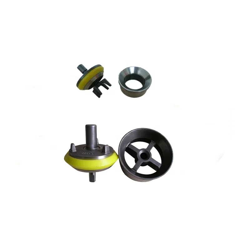
The valve and seat are made of forged alloy steel with deep carburized wear surface. We offer a full range of valves and seats which include full open valve and seat, 3 web / 4 web design valve and seat.
The valve comes with full open seat features four guide wings. They are either inertia welded to the valve body or uniformly forged with valve body. The urethane insert can be easily snapped on.
The 3 web / 4 web seat comes with stem guided valve. The urethane insert is tightened by steel plate and nut. It can be easily replaced with minimum down time. They offer long lasting service life under harsh service conditions.

Mystique Mud pump Coolant and Lubricant extends mud pump liner and piston life and provides internal lubrication and extra cooling to the coolant system of mud pumps. It extends the life of all liners, even ceramic. Mystique will not cause corrosion or rusting of iron, and is safe with all alloys. Recommened dilution rate of 12.5%. (25 gallons will treat a 200-gallon system.) For use on closed systems.

Gate valves, often called sluice valves, are common linear valve types often used in pipelines to start and stop liquid flow through ducting, allowing users to separate a section of pipe when required.
The fluid flow through the valve can be in either direction. These valves are often used in refineries and petrochemical plants applications where pressure is low.
However, many users do not have the necessary maintenance knowledge of the usage of gate valves and lack related guidance during assembling and installation of the valve. Minor problems spring up as a result.
Therefore in this article, we will be dishing out a complete guide to problems faced by users, how to fix them easily, handle and seat replacement guides, and other gate valve troubleshooting methods.
Before we go into how to test your valve, it is imperative to understand that valves are a crucial application in many industries, and they must function accurately by diverting the right pressure without leakages.
Testing, therefore, is performed as a gate valve maintenance procedure to assess the condition or health of an operational valve. These conditions include mechanical friction, flashing, cavitation, choked flow, erosion, and noise in valves, to name a few.
Middle-Pressure Test: In this test, the gate is opened to boost the pressure in the valve to the specified value. Then shut the gate, immediately remove the valve and look for leakage at the seals on both ends of the gate. Alternatively, directly insert the test medium into the plug on the cover, and check for the seals on both sides of the gate.
Blind Plate Test:This method also requires opening the ram to increase the test pressure of the valve to the specified value. After that, shut the gate and open the blind plate on one side to check for leakage. Turn the head and repeat the test above until it is qualified.
These tests are commonly conducted on valves with backseat elements, such as gate valves. The back seat tests follow the approved test procedure, but they often involve opening the valve with the packing gland loose or uninstalled.
The most common causes of gate valve failure are wear and the seat’s and wedge’s corrosion. The inner areas of a valve wear off over time, and corrosion can make the wedge stick in the open or closed position.
Therefore, gate valve manufacturers are careful about the safety aspects of the valves from the early design stage of the system. The failure of valves in the process control industry may lead to disastrous events that can jeopardize the safety of lives, investments, environment, and reputation.
Safety and risk management have to be important aspects of the system. Safe systems require industrial control valves communicating well with process liquid and equipment. Hence, let us explore some common problems faced with sluice and their solutions:
The leakage from the gate (sluice) valve is from the gate valve gland. This spillage results from a buildup of deposits against the seal, displacing the seal. To stop the leak, all that needs to be done are:
First, check whether the bolts joining the valve and the sluice are tight. If they are not sufficiently connected, the seal gasket ring and the surface of the flange sealing groove often result in leakage.
Also, check the contact surface of the seal ring and the flange sealing groove for sand holes, sand eyes, pitting, or impurities. These defects will be revealed at any time during the valve operation and pose serious threats to a safe operation. Hence, it is necessary that corresponding welding, repair, or clean-up is carried out.
Ensure careful operation, do not go hard when closing, do not open to the upper dead point, to the stop point should be reversed one or two turns of the handwheel so that the upper side of the threads close so that the medium to push the valve stem upward impacts. Make sure to operate carefully. Do not open and close it unduly.
Presence of defects like blisters, loose tissues, and squeezes on the valve and bonnet body. Also, when the quality of iron casting is below standard.
In the installation or maintenance of the sluice, leaking of the valve plate is the most common phenomenon and can be divided into two categories; leaking seal root and leaking sealing surface.
Secondly, inspect the sealing surface for sand eye, indentation, pitting, crack, and other defects, and if any of these occurs, the valve seat should be replaced.
For valve seats that have pressure springs, the elasticity of the spring must be in conformity with the requirements. If the elasticity is weakened, the pressure spring should be renewed. Additionally, remove the valve plate and adjust it to a suitable size if its T-shaped joint is too loose and results in a slope.
In the installation process, it is easy to drop the welding check, scrap iron, and impurities. Therefore, the clutter should be cleaned before installation. If you forget to clean up or clean up thoroughly, it will cause the valve plate to close less than the expected depth, resulting in leakage. To solve this, remove and clean the valve body.
Finally, the valve seat should be installed with special tools. Also, check whether the seat is installed correctly. If the thread is fastened less than the expected depth, there would be a leak. Hence, make sure special tools are used for re-installation.
As the valve ages, it seizes as water circulates via the pump around the central heating system and accumulates iron and dirt deposits. All the deposits stick to rough areas, getting in the mechanisms and causing the moving parts to jam up.
In most cases of breakage, repair work has to be done using a curb box key. Once the water is closed, you can remove the broken valve with little trouble.
Gate valve overhauling procedures are simple and last longer when installed and maintained correctly. The overhauling procedures and installation techniques vary slightly for different end connections (e.g., flanged, victuals, rolled groove), but the other instructions remain the same.
Industrial gate valves can be installed using any method; however, it is best if they can be installed upright, especially in larger sizes, for easy hand wheel access.
Extension spindle is used to operate the gate valves below the ground. In utility holes or above-ground installations, hand wheels or electric actuators may be used.
Ensure that no vertical force from the extension spindle clamps down directly on the top of the valve stem, especially when the valve is installed in a chamber with an extension spindle above ground level.
All welding works should be completed before installation, and ensure that the flange has cooled to ambient temperature by installing the sluice valve using the suitable gasket.
Ensure there is no misalignment of the valve relating to the flange. Lack of correct pipe alignment is the most common cause of valve problems. Ensure the valve is supported where necessary to reduce the load on the piping assembly.
Install the spacing bolts and ensure no damage to the valve seat. Also, adjust the face to face of the two flanges, so there is sufficient space to slip the valve in or out for servicing.
Tighten each of the bolts differently (one at a time). This is so that the pressure is evenly applied and a seal is formed between the valve, gasket, and flanges.
Gate valve maintenance procedures may seem too much to do, but a few minutes of your attention goes a long way to keep a system running smoothly. Valve maintenance can save you time and money in the long run, and ignoring it can leave you stuck with malfunctioning machinery, tubing, or pipes that may require taking apart or even replacing.
The only items that require maintenance on the gate valve are packing and the lubrication of the stem. The packing gland may require adjustment after installation, especially if the valve has been stored for a long time.
Replace the valve gate by removing the top body (bonnet) and stem. Unscrew the gate and replace it with a new part. Install top of the body and refit it into line.
When the gate valve handle isn’t working properly, your pipes may leak. A straightforward repair will be needed if the handle or extension rod connecting the handle to the valve is broken.
Order a Replacement Handle: If the plastic or metal T-handle at the end of the extension rod broke off, make an order for another one online. Also, order a replacement handle from your valve’s manufacturer. Check for the manufacturer’s name printed directly on the handle or a sticker near the valve.
Attach Your New Handle:The final step to this guide is to attach the new handle and install it by turning clockwise. Ensure your grip with the pliers is not released. This is to keep the extension rod from sliding inside the valve.
Glide your new handle over the end of the rod, and turn it until the threading hooks together. And when it does, keep turning it by hand until you can no longer. Then, release the handle and the pliers to finish replacing the valve’s handle.
Being the most common valve for water supply, the gate valve represents a linear motion isolation valve with the function of stopping or allowing the flow.
Like other types of valves, the gate valve has problems that users have to deal with. However, most of these failures can be prevented by proper maintenance.
This post discusses how to test, assemble and install your gate valve, their common failures, and how to fix them, including its seat and handle replacement guide.
Dombor valve is an industrial valve manufacturer that provides high-quality valve solutions to fit market requirements and pipe specifications. We pride ourselves on creating suitable valve types in various conditions. So contact us today!

There are countless types of valves for use across a variety of industries and applications. When it comes to flow control valves, valve types range from simple to sophisticated; some valves are complex enough to adjust automatically to pressure and temperature variations. No matter their construction, flow control valves are designed to regulate the flow or pressure of fluids, and they typically react to signals generated by flow meters or temperature gauges.
Flow control valves can serve a number of different functions within a hydraulic flow system depending on the specific type that is used. One of the most common uses of a flow control valve is to regulate the speed of motors or cylinders within the system. This function is possible due to the capability of a flow control valve to affect the rate of energy transfer at any given point in a system by impacting the flow rate.
The ability to reduce or increase pressure in a system has a number of benefits. System operators can use a flow control valve to rapidly depressurize a serviceable hose and change fittings quickly. They are also used in many consumer applications such as showers, faucets, and lawn watering systems to easily reduce the amount of water consumed without impacting the overall system performance. Flow control valves are also known for their reliability and typically have a long operating lifetime as they are not prone to clogging due to their design.
Due to these flexible performance parameters, flow control valves have found wide use in applications across materials handling, food processing, and automated factory and warehouse equipment.
Gate valves are general service valves primarily used for on/off, non-throttling service. Specifically, gate valves are used in applications requiring a straight-line flow of fluid with minimum
Gate valves may be used for several fluids. Generally, gate valves are applicable for potable water, wastewater, and neutral liquids; in temperatures between -20 and 70 degrees Celsius; maximum 5 meter/second flow velocity; and up to 16 bar differential pressure. Gate valves also are applicable for gases with temperatures between -20 and 60 degrees Celsius; maximum 20 meter/second flow velocity; and up to 16 bar differential pressure.
There are two types of gate valves: parallel and wedge-shaped. Parallel gate valves feature a flat gate between two parallel seats. Wedge-shaped gate valves are comprised of two inclined seats and an inclined gate that is just a bit mismatched.
A linear motion valve, globe valves stop, start, and regulate flow. Globe valves initiate closure via a plug featuring a flat or convex bottom that is lowered onto a horizontal seat situated in the center of the valve. When a user opens the valve, the plug raises to allow fluid to flow. Globe valves are used for on/off and throttling applications because the disk of the valve can be removed from the flow path completely or it can completely close the flow path. While this type of flow control valve does produce slightly higher pressure drops than straight-through valves like gate, plug, and ball valves, they are applicable in situations where the pressure drop through the valve is not a controlling factor.
The practical size limit for globe valves is NPS 12 (DN 300) because the entire system pressure exerted on the disc transfers to the valve stem. It is possible, however, to have globe valves larger than NPS 12 (DN 300), and manufacturers and engineers have created and used globe valves up to NPS 48 (DN 1200).
A cost-effective flow control valve, pinch valves are ideal for applications of slurries or liquids containing significant amounts of suspended solids. Pinch valves seal using one or more flexible elements like rubber tubes that become pinched to turn off the flow. These rubber sleeves are the valve’s only wetted part, and their flexibility allows pinch valves to close tightly around entrapped solids. Air or hydraulic pressure is placed directly on the elastomer sleeve to actuate pinch valves. A pinch valve’s body acts as a built-in actuator, which eliminates expensive hydraulic, pneumatic, or electric operators and results in the cost-effectiveness of this type of flow control valve.
There are many advantages to using diaphragm valves: they are extremely clean, feature a leak-proof seal, have a tight shut-off, are easy to maintain, and reduce leakage to the environment. Diaphragm valves also may be repaired without interrupting a pipeline. On the other hand, the disadvantages of using diaphragm valves include only being able to use them in moderate temperatures of -60 to 450 degrees Fahrenheit and in moderate pressures of approximately 300psi. Diaphragm valves cannot be used in multi-turn operations and do not have industry standard face-to-face dimensions. Also, the body of a diaphragm valve must be made of corrosive-resistant materials.
Needle valves are volume control valves that restrict flow in small lines. Fluid moving through the valve turns 90 degrees and flows through an orifice that serves as the seat for a cone-shape-tipped rod. The orifice size changes when the user positions the cone in relation to the seat. Needle valves are similar to globe valves in that they share a few design features and have similar benefits; for example, both needle valves and globe valves empower operators to change flow rate using a threaded rotating stem. The difference between needle valves and globe valves is the precision that needle valves can achieve. In fact, needle valves are an ideal choice for calibration applications because they are capable of being fine-tuned.
Flow control valves are necessary components in a broad range of industries. Determining which flow control valve type is best for your particular situation depends on a host of criteria, but the most commonly used types include gate valves, globe valves, pinch valves, diaphragm valves, and needle valves.
While the five types of flow control valves described above are some of the most commonly used valve types, there are other types of flow control valves with features that make them suitable for different applications. Here’s a look at a few other types of flow control valves.
Butterfly valve.Abutterfly valveis operated by rotating a disk within the flow area and, due to this design, it does not have linear flow characteristics. This makes these valves less precise than the more common flow control valve types above. For this reason, it can often be dismissed as a flow control valve choice even though it is useful in some applications that do not require a very high degree of accuracy. They are also a very affordable valve option, which makes it worthwhile to consider them in the right applications.
Plug valve. Plug valvescome in a variety of configurations and are operated by rotating a cylindrical or cone-shaped plug within the valve body to regulate the flow through a hollow area of the plug. For flow control applications the most common design is an eccentric plug valve, which uses a half plug to create a higher seating force with minimal friction as it is opened and closed. This has the advantage of greater shut off capability which is ideal for flow control situations.
Ball valve. Ball valvesare commonly used in flow systems across numerous industries due to their low cost, durability, and excellent shutoff capability. Similar to butterfly valves, they are not as effective for flow control applications that require a high degree of accuracy and control. One of the reasons for this is that a ball valve requires a high degree of torque to open and close that prevents an operator from making fine adjustments. There is also a certain amount of “play” between the stem and the ball which can make finding specific flow rates difficult. For flow control applications where a ball valve is possible, such as filling a tank to a reasonable degree of accuracy, a trunnion or v-port ball valve design is usually the best choice.
Flow control valves are used in a variety of applications, such as plumbing, mechanical, and gas dispensing applications. There are many factors to consider when choosing the appropriate flow control valve for an application, such as the characteristics of the fluid, service conditions, how frequently the valve is operated, and maintenance and environmental considerations. With a variety of valve types available, comparing the function and performance of various valves alongside your application specifications will help you identify the most suitable flow control valve for your application.

Mud Pump Valve & Seat are made of premium alloy steel through one-piece forging and carburizing treatment processes, thereby ensuring high intensity. In addition, the precise calculation is performed and CNC machining is conducted for the dimensional matching of the valve seat and valve body working angles to enhance the service life of the valve body and valve seat. Our valve products are able to work smoothly in normal mining and digging conditions for over 400 hours.
The present invention relates generally to valves used in pumps handling abrasive fluids. More specifically, the present invention provides an improved valve seat which significantly reduces the impact stress on valves and seat assemblies during the pumping operation, resulting in reduced wear on the valve assembly and improved reliability for the pumping system.
Pumping systems which are used to pump drilling mud and other abrasive fluids generally incorporate positive displacement pistons or plungers which operate in a reciprocating manner in individual cylinders. Each piston or plunger cylinder has a suction and discharge valve and valve seat operating alternatingly and independently to control flow into and out of each cylinder. The valve typically comprises a disc-shaped body portion which includes an elastomeric valve insert which serves to seal the valve when in the closed position and also serves to cushion the impact of the valve body in the valve seat. A lower conical seating surface of the valve body also makes contact with the valve seat when the valve is in the closed position.
Because of high pump pressures (between 2000 and 5000 psi) and the abrasive solid particles suspended in the drilling mud, valves and valve seats wear at a rapid rate and must be replaced frequently. One of the most significant points of impact stress in the valve assembly is the point of contact of the lower conical portion of the valve body and the valve seat when the valve is in the closed position. The extremely high differential pressures in the valve cause the conical portion of the valve body to engage the valve seat with a very high impact. The repetitive impact eventually causes the faces of the valve body and the valve seat to become worn and pitted. There is a need for an improved valve seat which reduces the impact stress related to the impact of the valve body with the valve seat.
The apparatus of the present invention overcomes the difficulties of the prior art by providing an improved valve seat which significantly decreases the impact stress caused by the impact of a mud pump valve body against the valve seat. The valve seat comprises a generally cylindrical body portion with a sealing surface which is sloped from the outer surface of the cylindrical body portion toward an interior throat of said cylindrical body portion. The valve body comprises a generally disc-shaped portion and a truncated contical portion. An elastomer insert is received in a groove in the valve body. The conical portion of the valve comprises a sloped face, including a metal portion and an elastomeric portion formed by the elastomeric insert. In the valve seat of the present invention, an annular pressure relief groove in the cylindrical body portion of the valve seat allows the sloped face of the valve seat to flex thereby relieving a significant amount of the impact load between the opposing faces of the valve assembly.
FIG. 2a is a cross-sectional view of the valve assembly of FIG. 1, showing the valve received in the valve seat with the valve in the closed position, just prior to maximum impact of the valve body against the valve seat.
FIG. 2b is cross-sectional view of the valve assembly of FIG. 1, showing the valve received in the valve seat with the valve in the closed position just after maximum impact of the valve body against the valve seat.
FIG. 1 is a perspective view of a mud pump valve assembly 10 comprising the improved valve seat of the present invention. The valve assembly shown in FIG. 1 is in the full open position. The valve assembly 10 is broadly comprised of a valve body 12 and a valve seat 14. The valve body comprises an upper valve guide 16 which maintains proper registration of the valve body within the pump housing. A plurality of valve guide feet 18 serve to maintain proper alignment of the valve with respect to the valve seat 14. The valve body comprises a generally disc-shaped portion 20 which is formed of metal, such as steel which has been heat treated by a carburizing process. The outer portion of the disc-shaped body has a generally C-shaped cross-section with an annular groove being defined by the interior of the C-shaped portion. A polyurethane or rubber insert is received in this groove. The insert serves to provide a partial damping of the impact of the valve body against the valve seat. However, this impact in most prior art systems is still high enough to cause significant wear on the operating faces of the valve body and the valve seat.
The lower portion of the valve body has a somewhat conical cross-section with a sloped surface illustrated by reference numeral 24. The sloped surface 24 comprises a rubber portion illustrated by reference numeral 26 and a metal portion illustrated by reference numeral 28. The valve seat 14 comprises a seating surface 30 with a portion 32 which engages the rubber portion 26 of the valve body surface and a portion 34 which engages the metal portion 28 of the valve body surface. FIG. 2a is a cross-sectional view of the valve assembly of FIG. 1, showing the valve received in the valve seat with the valve in the closed position, just prior to maximum impact of the valve body against the valve seat. FIG. 2b shows the valve received in the valve seat with the valve in the full closed position, with maximum impact of the valve body against the valve seat. Typically, the elastomer portion of the valve seating surface will make initial contact with the seating face of the valve seat. This is illustrated in FIG. 2a by the contact of the sloped face 26 of the elastomer insert 22 against the portion 32 of the sloped metal face of the valve seat. Note that the metal portion 28 of the sloped face of the valve body is not yet in contact with the portion 34 of the sloped face of the valve seat. The extremely high differential pressure on opposite sides of the valve, however, causes the elastomer insert 22 to compress rapidly to the position illustrated by the compressed elastomer insert 22 shown in FIG. 2b. The rapid compression of the elastomer insert results in an extremely high impact of the metal portion 28 of the valve face with the portion 34 of the valve seat face. In prior art valve seats this results in rapid wear of the metal portion 28 of the valve body and the portion 34 of the valve seat face. In the valve seat of the present invention, however, an annular pressure relief groove 36 allows the sloped face of the valve seat to flex thereby relieving a significant amount of the impact load between the opposing faces of the valve assembly.
Details relating to the valve seat 14 can be seen by referring to the cross-sectional illustration of FIG. 3. The outer surface of the valve seat comprises a valve seat shoulder 38 and a sidewall 40 having a conical taper. The slope of the sidewall 40 allows the valve seat to be received in a standard pump deck portion of a valve pot. The valve seat throat 42, defined by the internal cylindrical sidewall 44, transports the fluid passed through the valve assembly.
FIG. 4 is an enlarged view of a portion of the valve seat of the present invention showing details relating to the annular pressure relief groove 36. The relief groove is defined by vertical sidewalls 46 and 48 and an arch connecting the upper portions of the sidewalls 46 and 48. The arch is defined by two 90 degree segments with the inside segment having a radius which is two times as large as the radius of the outside 90 degree segment. The tangent point, illustrated by the reference numeral 50 is a point of smooth transition between the radii of the inside and the outside radii of the arch. The inside portion of the arch having the increased radius corresponds to the portion of the valve seat face which bears the impact of the metal portion of the valve body. Thus the impact load transmitted from the seating surface is dispersed over the larger radius inside the relief groove. This configuration maximizes flexure of the seating surface while preventing a stress concentration that would result in catastrophic shear failure of the seat.
Wear in the seating surface is directly proportional to the impact stress on the seating surface area of the valve seat. Impact stress "σ," which is reduced by the increased flexibility of the design of the present invention, is calculated using the following formula:
Utilizing finite element stress analysis, the calculated values for σs are approximately equal for the seating surface of a seat designed by the prior art and for the seating surface of the present invention. For both designs, the value of "h" is fixed and equal, being determined by the valve body and insert design. Again by finite element calculations, "y," deflection, is increased by a factor of 2 for the present invention. Using these values, the above equation yields values for impact stress, "σ," that are reduced by approximately 30% by the present invention.
The elastomeric insert is also positively affected by the present invention. The elastomeric seal, which is usually made of rubber or polyurethane material does not wear in the manner that the metal valve body and valve seat wear, i.e., through material loss. Material loss of the elastomeric seal is small during normal pump operation. Instead, the constant cyclical compression of the seal results in hysterisis in the seal that results in internal heat buildup and the eventual degradation of material strength to the point that the seal fails. As the metal valve and seat wear in the form of material loss from the impact stress, the amount of compression increases, hysterisis also increases to the point that material strength loss in the seal is accelerated and seal failure occurs after a shorter number of total cycles. Therefore, reduction in the wear rates of the metal valve body and valve seat also increases the life of the valve seal.
The flexible seat design of the present invention also improves pump operation because the valve opens faster and allows the pumped fluid to enter or leave the cylinder quicker. Because of the increased seat deflection, the seat stores energy that can be used to accelerate the valve to the open position before the piston or plunger begins the next stroke. In other words, the increased seat deflection acts like a recoiled spring which results in faster valve opening for smoother and more efficient pump operation.

Mud pump valve seats are used in on-shore and offshore oil and gas drilling operations and in pumps used in land-based fracking operations. Valves used in these types of pumping equipment operate at a very high frequency – up to one hertz (one cycle per second) – and are prone to high wear and degradation from hysteresis. Parker’s premium grade valve seats feature our Resilon® Polyurethane which has a high modulus of elasticity to successfully withstand high frequency operation and resist hysteresis.
Where typical urethane valves may last up to 400 hours, our proven valve seat designs with Resilon Polyurethane have lasted up to 800 hours (400 hours longer) – greatly improving drilling productivity through longer life. Longer valve seat life means maintenance intervals can be extended and production jobs can be completed before service is required.

Also known as Nova Tech Valve or Roughneck Valve or High Pressure Valve. Full open Seat & wing guided Valve design features a large metal-to-metal bearing area for long life, directly casted urethane insert on valve body results in a perfect round shape that prevents premature failures of the insert. The insert is casted around the serrations, thus failure due to tears from the serrations are eliminated Most importantly the insert is not stretched over the valve during installation; there are no residual stresses left, to shorten insert life.


 8613371530291