
mud pump valve seat failure in stock
The positive displacement mud pump is a key component of the drilling process and its lifespan and reliability are critical to a successful operation.
The fluid end is the most easily damaged part of the mud pump. The pumping process occurs within the fluid end with valves, pistons, and liners. Because these components are high-wear items, many pumps are designed to allow quick replacement of these parts.
Due to the nature of its operation, pistons, liners, and valve assemblies will wear and are considered expendable components. There will be some corrosion and metallurgy imperfections, but the majority of pump failures can be traced back to poor maintenance, errors during the repair process, and pumping drilling fluid with excessive solids content.
A few signs include cut piston rubber, discoloration, pistons that are hard to remove, scored liners, valve and seat pitting or cracks, valve inserts severely worn, cracked, or completely missing, and even drilling fluids making their way to the power end of the pump.
The fluid end of a positive displacement triplex pump presents many opportunities for issues. The results of these issues in such a high-pressure system can mean expensive downtime on the pump itself and, possibly, the entire rig — not to mention the costly repair or replacement of the pump. To reduce severe vibration caused by the pumping process, many pumps incorporate both a suction and discharge pulsation dampener; these are connected to the suction and discharge manifolds of the fluid end. These dampeners reduce the cavitation effect on the entire pump which increases the life of everything within the pump.
Poor maintenance — such as improper valve and seat installation — is another factor. Improper cleaning when replacing a valve seat can leave sand or debris in the valve seat area; preventing the new seat from properly forming a seal with the fluid cylinder, causing a pathway for a washout to occur. It is important to pull up on a seat firmly by hand and make sure it doesn’t pop out and is properly seated. The seats must be seated well, before resuming repairs. You should never reuse a valve seat if at all possible.
The fluid end is the most easily damaged part of the mud pump. The pumping process occurs within the fluid end with valves, pistons, and liners. Because these components are high-wear items, many pumps are designed to allow quick replacement of these parts.
A washout occurs when fluid and solids enter the area behind or underneath a valve seat and erode the sealing surface. Washouts are usually caused by one of three issues: a worn or cracked valve seat, improper cleaning of the valve seat and deck which creates a poor seat seal, and excessive sand content in your drilling fluid. Worn or cracked valve seats can allow fluid to enter the area around the valve seat and seat deck, creating a wash point on the valve seat and causing it to cut into the fluid cylinder and seat deck.
Additionally, the throat (inside diameter) can begin to wash out from extended usage hours or rather quickly when the fluid solids content is excessive. When this happens it can cut all the way through the seat and into the fluid end module/seat deck. This causes excessive expense not only from a parts standpoint but also extended downtime for parts delivery and labor hours to remove and replace the fluid module. With that said, a properly operated and maintained mud recycling system is vital to not only the pump but everything the drilling fluid comes in contact with downstream.

Customers said they wanted long-lasting, easy-to-use valves and seats, and we delivered. Made from domestically sourced steel, GD Energy Products valves feature a two-piece friction-welded design, proprietary bonded inserts, and innovative geometry to deliver significantly longer life. GD Energy Products’ field proven Valves & Seats meet API Standard, and come with our “Ready Inventory” promise that we’ll have it in stock, when you need it.
Our full-open valves and seats are designed for use in GD Energy Products PZ, F-Series, and National 12P lines of triplex drilling pumps. This gives you options to use these parts across your whole fleet of pumps.

The fluid end of a duplex or triplex pump offers hundreds of opportunities for error. The results of an error in such a high-pressure system can mean (1) expensive downtime on the pump and maybe the entire rig, (2) expensive repair-replacement, and (3) possible injury or death of a crewman or a company man. Under the laws of nature, pump pistons and liners will wear, and there will be some corrosion and metallurgical imperfections, but the majority of pump failures are manmade. Theoretically, thorough training and retraining should avoid most mud pump problems. Realistically, a critical failure analysis during repair will be necessary to determine how to correct the failure. Telltale signs of trouble are distortion of piston rods, frayed piston polymer, discoloration, odor, hard-to-remove piston, rod cracks, pitting, total fracture, valve seat wear, and unsuitable external appearance.

abstractNote = {Failure of a liner seal is one of the more critical failures on a mud pump because this seal interfaces with the pump body. Therefore, failures, usually damage the pump body, leading to repair or replacement of the fluid end itself. One of the more common liner seal problems involves counter-bore-type seals. This type of seal is easily affected by two aspects of the problem that are found in the mud pump fluid end-wear and foreign matter in the seal groove. Factors relative to difficult liner removal are discussed. Piston damage, careless seal installation and corrosion damage are also examined.},

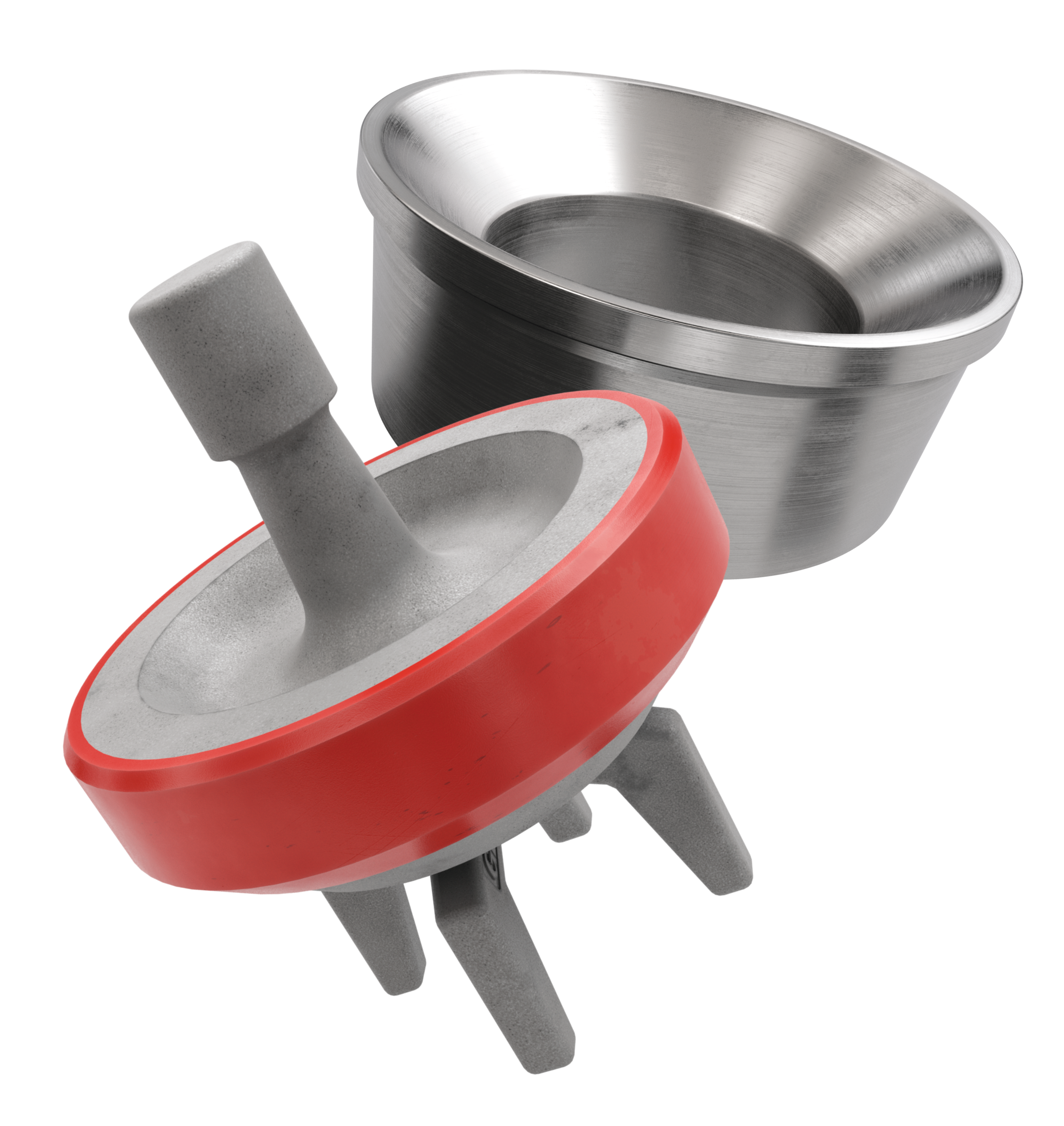
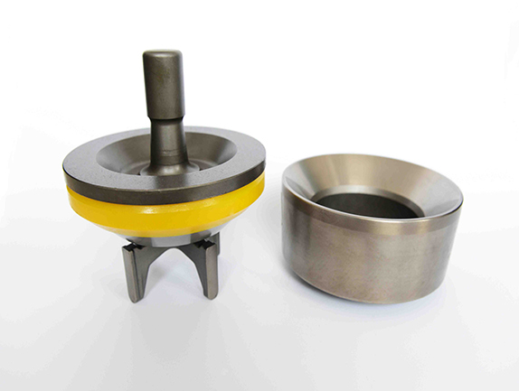
The Caliber® 4-web valve and seat are designed for today’s high pressure drilling conditions. Each piece is forged from a single piece of proprietary, high-strength alloy steel and is case hardened to precisely controlled levels. We have molded our high temperature, high impact resistant urethane to the valve body in order to eliminate the existing gap you will find on replaceable insert type valves.
The 4-web design holds the valve weight to a minimum by increasing the load bearing area. In order to allow quick flushing of solid matter we use a steep angle that also increases the metal-to-metal sealing area. Each part is individually inspected to ensure performance and satisfaction.

Mud pump valve seats are used in on-shore and offshore oil and gas drilling operations and in pumps used in land-based fracking operations. Valves used in these types of pumping equipment operate at a very high frequency – up to one hertz (one cycle per second) – and are prone to high wear and degradation from hysteresis. Parker’s premium grade valve seats feature our Resilon® Polyurethane which has a high modulus of elasticity to successfully withstand high frequency operation and resist hysteresis.
Where typical urethane valves may last up to 400 hours, our proven valve seat designs with Resilon Polyurethane have lasted up to 800 hours (400 hours longer) – greatly improving drilling productivity through longer life. Longer valve seat life means maintenance intervals can be extended and production jobs can be completed before service is required.
However, the engine valves (particularly the exhaust valves) shouldn’t be overlooked for the role they play in keeping an engine cool. The exhaust valves take 75 percent of the heat from the combustion chamber and the valve seats have the responsibility of helping to cool them off by drawing heat away from the valves and conducting it into the cylinder head.
A valve seat must actually do several things – it must support and seal the valve when the valve closes, it must cool the valve, and it must resist wear and recession. Consequently, a performance valve seat material should provide a certain amount of dampening to help cushion the valve when it closes at high rpm. Very hard materials, especially on the intake side, are not the best choice because intake valves tend to be larger, heavier and close at faster rates than exhaust valves.
• Frictional Stress occurs primarily between the valve stem and the guide as the valve opens and closes, but is also seen between the valve and the seat due to the valve’s relative motion;
Seats are available in a range of materials ranging from nodular/ductile iron alloys and powder metal steel seats to hard aluminum-copper and bronze alloys and beryllium copper alloys. Many valve seat suppliers have their own proprietary alloys while others use industry standard alloys.
As a rule, most experts recommend replacing OEM valve seats with ones that are of a similar material, except in cases where extra durability is required because of a change in fuels (converting to propane or natural gas, for example), or an engine is being built for racing.
Increasingly, that means using powder metal seats. Nearly all late-model domestic and import engines (perhaps 90 percent or more) come from the vehicle manufacturer with seats made of powder metal. These types of seats are very hard and durable, so they typically show little wear at high mileages. Consequently, the seats may need little work when the cylinder head is rebuilt.
A key difference between seat types is the production process. Cast alloy seats are made by melting and mixing different metals together so they combine chemically. The molten material is then poured into a mold and cast to shape then allowed to cool. The rate of cooling and subsequent heat treatment of the metal determines its microstructure, hardness, strength and other physical properties.
Powder metal seats, by comparison, are made by mixing together precise amounts of various dry metal powders (iron, tungsten carbide, molybdenum, chromium, vanadium, nickel, manganese, silicon, copper, etc.), forcing the mixed powders though a series of dies that compact the powder under intense pressure (100 tons, in some cases) into a near net shape. The “green state” seats are very fragile and can be easily broken. The sintering process then causes the powders to bond together and form a solid composite matrix with very uniform and consistent properties.
Another advantage of the powder metal process is that parts can be manufactured very close to final tolerances, reducing the amount of machining needed to finish the part to size. Runout on a cast seat is typically seen at 0.003˝ to 0.005˝; on a powder metal seat it is about 0.001˝. And, at a microscopic level, cast seats can have a rougher surface, which increases friction and accelerates wear. Powder metal seats typically have a smoother surface, requiring less machining effort.
Vehicle manufacturers didn’t just switch from cast alloy seats to powder metal seat inserts because they care about easing your machining effort, of course. The primary driver is to extend durability and to meet emissions certifications of 150,000 miles or more depending on the application and model year.
Powder metal seats are very good at handling thermal stress as well as impact stress, and typically show minimal wear after tens of thousands of miles of use. The homogeneous consistency of a powder metal seat also improves heat transfer, which is good for the valves, too. Powder metal seats also tend to experience less micro-welding between the seat and valve even at high combustion temperatures, which helps extend the life of both components.
The seat alloy and hardness must also be matched to the type of fuel used and the engine application and compatible with the type of valves that are installed in the engine. Again, there are often differences of opinion regarding the selection and use of various seat materials.
It’s more noticeable in performance engines. Titanium valves do not shed heat as quickly as stainless steel valves, so the tradeoff for switching from steel to titanium to save weight is often hotter running valves. The higher the temperature of the exhaust valve, the greater the risk of the valve causing a preignition or detonation problem.
There is also increased risk of the valve burning. That’s why many suppliers of titanium valves recommend seat materials such as beryllium copper. Some of the more recognizable engines with head issues have been the GM LS3 engine as well as BMW and Mercedes and the Chrysler 3.7L, 4.7L, 5.7L and 6.1L engines. Copper-infiltrated seats are used at the OE level and are available in the aftermarket as well.
For racing applications using either stainless steel or titanium exhaust valves, some suppliers recommend a sintered valve seat insert, which includes a blend of finely dispersed tungsten carbide in a matrix of tempered M22 tool steel and special alloy iron particles. These powder metal seats have a very uniform microstructure, and are highly machinable. Because powder metal seats harden as they age, they don’t have to be as hard initially to provide good long term durability, and the self-lubricating qualities of the material allows it to handle a wide variety of fuels, including unleaded and leaded gasoline, straight alcohol, nitrous oxide and nitro methane. A shot of nitrous will cause combustion temperatures to soar, but the dose usually doesn’t last long enough to have any detrimental affect on the seats.
The next step up is a high alloy seat material, for applications where high heat resistance is required, such as a propane or natural gas fired stationary engine but also for high performance engines, heavy-duty and extreme duty engines where longevity is a must. Seats are made out of high-speed tungsten carbide tool steel, which gives it ceramic-like characteristics for extreme temperature resistance.
Conversely, because they tend to run much cooler than exhaust valves, low alloy seats work well with intake valves in performance applications, even in such extreme cases as offshore racing boats that run for hours on end.
Anything that interferes with a seat’s ability to cool the valves (such as a loose fit, poor surface finish or deposits between the seat and its counterbore) can lead to premature valve failure and expensive comebacks, so a cylinder head job often requires valve guide and seat work to restore it for service or to improve performance. In order for a valve to seat correctly, for efficiency and power, engine builders must replace or bring back to spec all valve seats and guides.
When considering the steps necessary to repair or replace valve seats, be aware that with two types of cylinder heads you have three options: aluminum with removable valve seats or cast iron, with removable or integral hardened seats. If the cast iron head has integral seats it will need to be machined to replace the seat. If the head is aluminum, the seat counterbore may have to be machined to accept an oversize seat if the bore is loose, deformed or damaged. Either way, you’ll need to figure the amount of interference that is required for the new seat before cutting the head on a seat-and-guide machine.
Valve seat replacement is required if the cylinder head was warped and needed to be straightened before resurfacing. Similarly, if an aluminum head was cleaned by heating; if the valve’s mating surface has receded below factory specifications; or if machining the head would cause the seat to fall below factory specs, the seat must be replaced.
Integral seats in a cast iron head should be replaced if the head has been ground before, because the hardened depth of the head used in the seat area will be too shallow to allow a second grinding.
If the valve seat insert shows evidence of being loose or doesn’t have adequate interference; if there is evidence of corrosion on the cylinder head around the outside diameter of the valve seat; or if there is evidence that the seat has any cracking, burning, pitting or fissures, the seats must be replaced.
Nonintegral valve seats can fail for a number of reasons, especially when they show signs of being cracked or are too worn to be reground or remachined. Seats can crack from any of the stresses listed earlier.
Another cause of seat damage is valve recession, which takes place when the seats get hot and microscopic welds form between the valve face and seat. A small amount of recession results from normal high mileage wear, but it can also occur when unleaded gasoline or a fuel such as propane or natural gas is used in an engine without hardened seats.
Every time the valve opens, tiny chunks of metal are torn away and blown out the exhaust. Over time, the seat is gradually eaten away and the valve slowly sinks deeper and deeper into the head. Eventually the lash in the valvetrain closes up and prevents the valve from seating. This causes the valve to overheat and burn.
Misdiagnosis of the lost compression may lead you to believe the engine has a bad valve – in reality, improper valve seat selection and installation may have been the underlying cause of the failure, and the time bomb may have started ticking thousands of miles earlier.

The following case study describes a proven method of how to detect failures in the suction or discharge valves inside positive displacement pumps with a unique method of vibration analysis. The determination to find a reliable method of detection led us to a greater understanding of our equipment and processes, including working with the vendor to implement a design change. This paper will describe a journey from repeated failures to improved equipment reliability and lower maintenance costs.
Over time, knowledge and experience with PDM technologies grew exponentially. In the early 1990s, portable vibration monitoring was advancing and industries could see the potential, but there were only a few vendors to choose from. Vibration technology is predominantly used to monitor the typical assortment of rotating equipment found at industrial plants such as pumps, fans, motors, compressors, turbines, conveyors, gearboxes, and so on. This paper focuses on positive displacement pumps like the one shown in Figure 1.
Reciprocating positive displacement pumps like the one shown in Figure 1 operate in many different industries around the world. Reciprocating pumps move fluid using one or more oscillating pistons, plungers, or membranes (diaphragms), while valves in the pump-head restrict fluid motion to control the desired fluid direction.
During the suction stroke the plunger retracts, decreasing the pressure in the chamber and causing the suction valve to open, resulting in the fluid entering the cylinder. In the forward stroke, the pressure in the chamber increases, and the plunger pushes the liquid out through the discharge valve and into the discharge pipe at a high velocity and high positive pressure.
The Yara Belle Plaine plant contains a number of triplex plunger pumps of various sizes that operate at very high pressures. The plungers, seals, discharge valves and suction valves all come into contact with the fluid being transferred, and the material choices are based on the fluid transferred.
Typically, industrial plants use vibration analysis to monitor the condition of the rotating equipment with respect to bearing faults, looseness, alignment, imbalance, plus many other mechanical issues. In this paper the discussion turns to how vibration analysis was used to determine the condition of the suction and discharge valves in the pump-head of triplex positive displacement pumps and, specifically, whether these pump valves were passing.
Why was it useful to know whether one or more of the valves in the pump head was passing? It is helpful to start by describing the process to discover that monitoring the condition of these pump valves was even possible.
Early on, the valves were failing often in the plant’s midsize pumps. Vibration data was collected every two weeks on these pumps, but the valve condition was not found in the vibration data. We tried collecting overall vibration (velocity), spectral data (velocity and acceleration), overall high frequency envelope data (HFE) (spike energy/gSE), and time waveforms (acceleration and velocity) to try to discover some indication that signified the valves were failing. Even the low-tech stethoscope method was tried (and I hate to admit, even the screwdriver to the ear).
This went on for a few years and the pump valves continued to fail in the midsize pumps due to premature wear and catastrophic failure. In most cases, the valve disc and seat were becoming wire-drawn which caused a leak path. See Figure 2.
Confidence using gSE motivated us to try this measurement on process valve leaks. There were issues in the process plant in isolating a piping system for a hydrotest. The system had a number of isolation valves, but one or more valves was passing, preventing completion of the hydrotest.
The theory was that if a process valve was slightly open, it should emit high frequencies or possibly ultrasonic frequencies. The smaller the opening that the liquid or air had to pass through, the higher the frequency. Overall gSE was tried because it was a measure of ultrasonic vibration frequency. This turned out to be unsuccessful because there needed to be a baseline measurement to compare with in order to be certain that the process valve was passing. Only the gSE Time Waveform could show us the frequencies needed for analysis.
That exercise led us back to the pump valves, and the collection of gSE Time Waveforms was added to the two-week vibration routes on the midsize triplex pumps. The difference between this and the process valves was that, by collecting data regularly, baseline data was gathered from when the valves were in good condition. The next valve failure would allow us to study the historical data that had been collected to find out if this new measurement was going to help.
Before a failure occurred, we delved into what the pump valves were doing. Refer to the parts in Figure 2. There was sliding motion between the sealing disc and the valve stem along the bushing; spring action; impacting when the disc landed on the valve seat; looseness; and there was liquid flowing through the valve openings. The valve disc travelled from a fully closed position resting on the valve, to fully open, at some distance away from the valve seat.
The conclusion was that flow-induced high frequency vibration should be greatest when the valve disc was as near the fully closed position as possible but still allowing fluid to pass by the sealing surfaces – through a small opening. How could we prove and measure this?
When the air passed through the air nozzle, the rectified gSE TWF clearly displayed a unique pattern, with plateaus in the TWF for the duration of the leak. This allowed us to associate a vibration measurement to the pump valve condition. Whether liquid or air was passing through a small opening, the results remained the same: ultrasonic vibration frequencies were generated.
Figure 4 and Figure 5 show the gSE Time Waveforms collected from the pump-head of the midsize pumps. Vibration readings were collected from each pump valve location, for three suction plus three discharge valves.
Figure 4 is the time waveform when the pump valves were in good condition. The narrow spikes in this gSE time waveform represent the smallest of openings when each valve is nearest the fully closed position.
Figure 5 is the time waveform when a valve was passing. It consists of normal ultrasonic emissions from the valves opening and closing, separated by plateaus of high ultrasonic vibration. The duration of the plateaus is equal to the time elapsed by the plunger stroke in one of the directions (suction or discharge stroke), and is equivalent to one half-revolution of the pump shaft. The difference between the time waveforms is clear.
Attention was focused on the mid-size pumps before moving on to the smaller and larger plunger pumps. There were more valve failures on the mid-size pumps. Now that we could see the failures occurring, there was a greater understanding of the level of unreliability and the failure modes. This led to discussions with the pump vendor for ways to improve the reliability. The vendor offered the option of installing valves of an upgraded design. The new design proved successful and rarely failed.
We were sufficiently confident with the results to add this unique vibration measurement to the route readings collected on all the other triplex pumps on site. The valve failures on the other pumps were less frequent, but this failure mode could be seen as it progressed along the P-F curve.
The midsize pumps like the one shown in Figure 6 had the most frequent valve failures, which made it necessary to learn how to detect pump valve failures.
To illustrate another benefit of monitoring the pump valve condition, Figures 7 and 8 show the valve damage at the end of its mechanical life on the P-F curve. The pump valve in the farthest right cylinder in Figure 7 failed catastrophically and resulted in collateral damage. The pump could not meet process requirements, had mechanically failed, and had to be shut down for maintenance. Repairs were not isolated to the valves and the repair costs were very high.
The valve from a midsize pump in Figure 8 also failed mechanically. Pieces of the valve broke apart and were free to flail around inside the chamber for this plunger. This caused damage to other parts inside the pump and had the potential to cause damage downstream of the pump.
The pump in Figure 9 was the largest of the plant’s plunger pumps, a high pressure, high volume ammonia liquid process pump. The equipment train consisted of a 900 hp electric motor, variable speed torque converter, triple reduction gearbox, and pump with 150 mm diameter plungers operating at over 18 MPa.
In these pumps, the suction and discharge pump valves were integral. These are more sophisticated but perform the same function as two separate valves. These valves are large, heavy (over 50 kg), and expensive, and operate in a hazardous service requiring more planning, preparation, and safety requirements to replace them.
For this pump, a method of determining which valve(s) were passing was developed by setting up a timing mark on the pump input shaft and performing synchronised time waveform analysis using the gSE vibration measurement units. This allowed for the opportunity to replace only the valves that were passing, if desired.
During a plant turnaround, when the pump crankcase was open for a complete pump rebuild, the crankshaft was rotated so that the plunger closest to the drive side of the pump was placed in the top dead centre (TDC) position. Reflective tape was attached to a portion of the input shaft that protruded outside the pump case (see Figure 10).
The reflective tape was placed in the horizontal plane to be used as a timing mark for the synchronous time waveform measurement. That way the position of each plunger could be identified in the resulting synchronous time waveforms to identify which valve was open or closed and when. Note that these pumps were variable speed, which made the timing crucial to this measurement.
The spikes in the TWF are at the end of the plunger strokes when the discharge/suction valves open and close – the moments when the valve openings were the least.
The start of the synchronous time waveform in this case (at 0 seconds in Figure 12) was when cylinder number one (North) began its compression stroke. This was the moment closest to the opening of the discharge valve on that cylinder. From then, the position of all the valves and plungers within their cycles could be derived. Then, from the patterns in the TWF, it could be seen if any, and which, valves were passing. Figure 11 (left) and Figure 12 are used together to show the reader how the position of each cylinder was identified.
One full rotation of the crankshaft is 360 degrees of rotation. For 180 degrees of shaft rotation, the plungers are in either a compression stroke or a suction stroke. The plungers have ±120 degrees of phase difference between each other. The speed was measured by the timing mark and a laser tachometer. The signal from the laser tachometer was fed into to the portable data collector and was required for the synchronous time waveform measurements. These relationships are seen in Figure 12. The results of this TWF show that the valve for the North cylinder was passing on the compression stroke. Six rotations of the crankshaft are shown in the TWF, with the valve passing on each rotation (one plateau/rotation).
Regarding the plant’s smallest triplex shown in Figure 13, the pump valves are much smaller, about the size of a thimble of thread. The lack of seal of a pump valve in this situation resulted in the pump failing to satisfy process requirements and it was taken offline by Operations. A standby pump had to be put online.
The passing valve caused flow and pressure fluctuations in the seal flush to another pump. The low-level pressure monitors triggered an alarm and process logic control caused the standby pump to start automatically. A high priority work order was initiated to replace the pump valves.
If the standby pump had also failed, there would have been a cascade effect, causing other pumps to shut down and a loss of production. This proved that smaller pumps with much smaller, less expensive valves could result in large economic losses.
The pump valve in Figure 14 (left) failed to seal in a different mode from the larger pump valves. The valve disc had a flat surface when in new condition. Over time, the thousands of cycles that the valve opened and closed caused the perimeter of the face of the valve disc to wear down – Figure 14 (right). This was the surface of the disc that would contact the valve seat on each cycle and was considered normal wear.
Slide wear on the outside diameter of the valve disc plus internal slide wear on the inside of the valve body resulted in increased radial clearance between the disc and valve body. At some time, an event occurred that caused the valve disc to shift position sideways. The disc then failed to land on the valve seat in the same location along the wear surfaces. This caused part of the unworn face of the valve disc to land on the valve seat during each cycle. The result was the disc landing at a slight angle in the closed position and leaving a small uneven gap between the disc and seat, a leak that caused ultrasonic frequencies that could be measured and seen in the gSE time waveform.
Since this was a discharge pump valve, the higher pressure in the discharge pipe caused liquid to flow back into the chamber of this plunger during its suction stroke. This explained the pressure and flow fluctuations.
One discharge pump valve had failed to seat properly. The plateaus from the lack of seal can be seen in the gSE Time Waveform in Figure 15. In this case, the lack of seal in the pump valve was occurring when this plunger was on its suction stroke.
The pump valves were small and inexpensive, so all the valves were replaced during the maintenance activity. There was normal wear on all other valves but changing all the valves improved the future reliability of the pump. This is a situation where it was not important to know which valve had failed. Logic dictated replacing all valves.
In summary, the condition of the valves in positive displacement pumps can be monitored. Learning how vibration technology could be used in this application took years to accomplish but the rewards were well worth the effort. We also learned how to think creatively and use a common PDM technology in a non-standard application.
The benefits of knowing when pump valve defects have begun can range from economic to safety. Planning and scheduling are improved. There could be RCA and FMEA activities that result in design or operational changes. Production losses and failure to meet commitments to customers could be avoided. Depending on the level of hazardous product flowing through these pumps, safety and environmental issues may be avoided. Positive displacement pumps are often high pressure, high flow equipment. The more that is known about condition of these pumps, the more safely and reliably they can be operated.

Drilling consumables such as mud pump systems and their components can drastically increase your uptime while reducing costs and health/safety/environmental (HSE) risks. To support your drilling needs, Forum’s patented P-Quip® mud pump system offers a single-source solution that integrates high-quality fluid end components for maximum longevity and performance.
With more than 20 years of successful operation in severe environments, P-Quip offers a proven track record for the lowest cost of ownership in the industry. As part of our commitment to quality, our mud pump parts use patented Banded Bore™ technology that significantly reduces stress concentrations and leads to longer module life.


 8613371530291