
mud pump wikipedia for sale

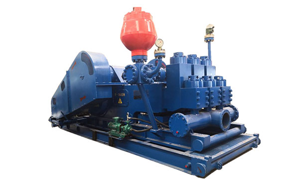
A mud pump (sometimes referred to as a mud drilling pump or drilling mud pump), is a reciprocating piston/plunger pump designed to circulate drilling fluid under high pressure (up to 7,500 psi or 52,000 kPa) down the drill string and back up the annulus. A mud pump is an important part of the equipment used for oil well drilling.
Mud pumps can be divided into single-acting pump and double-acting pump according to the completion times of the suction and drainage acting in one cycle of the piston"s reciprocating motion.
Mud pumps come in a variety of sizes and configurations but for the typical petroleum drilling rig, the triplex (three piston/plunger) mud pump is used. Duplex mud pumps (two piston/plungers) have generally been replaced by the triplex pump, but are still common in developing countries. Two later developments are the hex pump with six vertical pistons/plungers, and various quintuplexes with five horizontal piston/plungers. The advantages that these new pumps have over convention triplex pumps is a lower mud noise which assists with better measurement while drilling (MWD) and logging while drilling (LWD) decoding.
The fluid end produces the pumping process with valves, pistons, and liners. Because these components are high-wear items, modern pumps are designed to allow quick replacement of these parts.
To reduce severe vibration caused by the pumping process, these pumps incorporate both a suction and discharge pulsation dampener. These are connected to the inlet and outlet of the fluid end.
The pressure of the pump depends on the depth of the drilling hole, the resistance of flushing fluid (drilling fluid) through the channel, as well as the nature of the conveying drilling fluid. The deeper the drilling hole and the greater the pipeline resistance, the higher the pressure needed.
With the changes of drilling hole diameter and depth, the displacement of the pump can be adjusted accordingly. In the mud pump mechanism, the gearbox or hydraulic motor is equipped to adjust its speed and displacement. In order to accurately measure the changes in pressure and displacement, a flow meter and pressure gauge are installed in the mud pump.
The construction department should have a special maintenance worker that is responsible for the maintenance and repair of the machine. Mud pumps and other mechanical equipment should be inspected and maintained on a scheduled and timely basis to find and address problems ahead of time, in order to avoid unscheduled shutdown. The worker should attend to the size of the sediment particles; if large particles are found, the mud pump parts should be checked frequently for wear, to see if they need to be repaired or replaced. The wearing parts for mud pumps include pump casing, bearings, impeller, piston, liner, etc. Advanced anti-wear measures should be adopted to increase the service life of the wearing parts, which can reduce the investment cost of the project, and improve production efficiency. At the same time, wearing parts and other mud pump parts should be repaired rather than replaced when possible.

Centrifugal pumps are used to transport fluids by the conversion of rotational kinetic energy to the hydrodynamic energy of the fluid flow. The rotational energy typically comes from an engine or electric motor. They are a sub-class of dynamic axisymmetric work-absorbing turbomachinery.volute chamber (casing), from which it exits.
Common uses include water, sewage, agriculture, petroleum, and petrochemical pumping. Centrifugal pumps are often chosen for their high flow rate capabilities, abrasive solution compatibility, mixing potential, as well as their relatively simple engineering.centrifugal fan is commonly used to implement an air handling unit or vacuum cleaner. The reverse function of the centrifugal pump is a water turbine converting potential energy of water pressure into mechanical rotational energy.
According to Reti, the first machine that could be characterized as a centrifugal pump was a mud lifting machine which appeared as early as 1475 in a treatise by the Italian Renaissance engineer Francesco di Giorgio Martini.Denis Papin built one using straight vanes. The curved vane was introduced by British inventor John Appold in 1851.
Like most pumps, a centrifugal pump converts rotational energy, often from a motor, to energy in a moving fluid. A portion of the energy goes into kinetic energy of the fluid. Fluid enters axially through eye of the casing, is caught up in the impeller blades, and is whirled tangentially and radially outward until it leaves through all circumferential parts of the impeller into the diffuser part of the casing. The fluid gains both velocity and pressure while passing through the impeller. The doughnut-shaped diffuser, or scroll, section of the casing decelerates the flow and further increases the pressure.
The color triangle formed by velocity vector u,c,w called "velocity triangle". This rule was helpful to detail Eq.(1) become Eq.(2) and wide explained how the pump works.
Vertical centrifugal pumps are also referred to as cantilever pumps. They utilize a unique shaft and bearing support configuration that allows the volute to hang in the sump while the bearings are outside the sump. This style of pump uses no stuffing box to seal the shaft but instead utilizes a "throttle bushing". A common application for this style of pump is in a parts washer.
In the mineral industry, or in the extraction of oilsand, froth is generated to separate the rich minerals or bitumen from the sand and clays. Froth contains air that tends to block conventional pumps and cause loss of prime. Over history, industry has developed different ways to deal with this problem. In the pulp and paper industry holes are drilled in the impeller. Air escapes to the back of the impeller and a special expeller discharges the air back to the suction tank. The impeller may also feature special small vanes between the primary vanes called split vanes or secondary vanes. Some pumps may feature a large eye, an inducer or recirculation of pressurized froth from the pump discharge back to the suction to break the bubbles.
A centrifugal pump containing two or more impellers is called a multistage centrifugal pump. The impellers may be mounted on the same shaft or on different shafts. At each stage, the fluid is directed to the center before making its way to the discharge on the outer diameter.
A common application of the multistage centrifugal pump is the boiler feedwater pump. For example, a 350 MW unit would require two feedpumps in parallel. Each feedpump is a multistage centrifugal pump producing 150 L/s at 21 MPa.
The energy usage in a pumping installation is determined by the flow required, the height lifted and the length and friction characteristics of the pipeline.
An oilfield solids control system needs many centrifugal pumps to sit on or in mud tanks. The types of centrifugal pumps used are sand pumps, submersible slurry pumps, shear pumps, and charging pumps. They are defined for their different functions, but their working principle is the same.
Magnetically coupled pumps, or magnetic drive pumps, vary from the traditional pumping style, as the motor is coupled to the pump by magnetic means rather than by a direct mechanical shaft. The pump works via a drive magnet, "driving" the pump rotor, which is magnetically coupled to the primary shaft driven by the motor.gland is needed. There is no risk of leakage, unless the casing is broken. Since the pump shaft is not supported by bearings outside the pump"s housing, support inside the pump is provided by bushings. The pump size of a magnetic drive pumps can go from few watts of power to a giant 1 MW.
The process of filling the pump with liquid is called priming. All centrifugal pumps require liquid in the liquid casing to prime. If the pump casing becomes filled with vapors or gases, the pump impeller becomes gas-bound and incapable of pumping.
In normal conditions, common centrifugal pumps are unable to evacuate the air from an inlet line leading to a fluid level whose geodetic altitude is below that of the pump. Self-priming pumps have to be capable of evacuating air (see Venting) from the pump suction line without any external auxiliary devices.
Centrifugal pumps with an internal suction stage such as water-jet pumps or side-channel pumps are also classified as self-priming pumps.American Marsh in 1938.
Centrifugal pumps that are not designed with an internal or external self-priming stage can only start to pump the fluid after the pump has initially been primed with the fluid. Sturdier but slower, their impellers are designed to move liquid, which is far denser than air, leaving them unable to operate when air is present.check valve or a vent valve must be fitted to prevent any siphon action and ensure that the fluid remains in the casing when the pump has been stopped. In self-priming centrifugal pumps with a separation chamber the fluid pumped and the entrained air bubbles are pumped into the separation chamber by the impeller action.
The air escapes through the pump discharge nozzle whilst the fluid drops back down and is once more entrained by the impeller. The suction line is thus continuously evacuated. The design required for such a self-priming feature has an adverse effect on pump efficiency. Also, the dimensions of the separating chamber are relatively large. For these reasons this solution is only adopted for small pumps, e.g. garden pumps. More frequently used types of self-priming pumps are side-channel and water-ring pumps.
Another type of self-priming pump is a centrifugal pump with two casing chambers and an open impeller. This design is not only used for its self-priming capabilities but also for its degassing effects when pumping twophase mixtures (air/gas and liquid) for a short time in process engineering or when handling polluted fluids, for example, when draining water from construction pits.This pump type operates without a foot valve and without an evacuation device on the suction side. The pump has to be primed with the fluid to be handled prior to commissioning. Two-phase mixture is pumped until the suction line has been evacuated and the fluid level has been pushed into the front suction intake chamber by atmospheric pressure. During normal pumping operation this pump works like an ordinary centrifugal pump.
Baha Abulnaga (2004). Pumping Oilsand Froth (PDF). 21st International Pump Users Symposium, Baltimore, Maryland. Published by Texas A&M University, Texas, USA. Archived from the original (PDF) on 2014-08-11. Retrieved 2012-10-28.
Moniz, Paresh Girdhar, Octo (2004). Practical centrifugal pumps design, operation and maintenance (1. publ. ed.). Oxford: Newnes. p. 13. ISBN 0750662735. Retrieved 3 April 2015.

An airlift pump is a pump that has low suction and moderate discharge of liquid and entrained solids. The pump injects compressed air at the bottom of the discharge pipe which is immersed in the liquid. The compressed air mixes with the liquid causing the air-water mixture to be less dense than the rest of the liquid around it and therefore is displaced upwards through the discharge pipe by the surrounding liquid of higher density. Solids may be entrained in the flow and if small enough to fit through the pipe, will be discharged with the rest of the flow at a shallower depth or above the surface. Airlift pumps are widely used in aquaculture to pump, circulate and aerate water in closed, recirculating systems and ponds. Other applications include dredging, underwater archaeology, salvage operations and collection of scientific specimens.
Airlift pumps are often used in deep dirty wells where sand would quickly abrade mechanical parts. (The compressor is on the surface and no mechanical parts are needed in the well). However airlift wells must be much deeper than the water table to allow for submergence. Air is generally pumped at least as deep under the water as the water is to be lifted. (If the water table is 50 ft below, the air should be pumped 100 feet deep). It is also sometimes used in part of the process on a wastewater treatment plant if a small head is required (typically around 1 foot head).
The liquid is not in contact with any mechanical elements. Therefore, neither the pump can be abraded (which is important for sandwater wells), nor the contents in the pipe (which is important for archeological research in the sea).
Conventional airlift pumps have a flow rate that is very limited. The pump is either on or off. It is very difficult to get a wide range of proportional flow control by varying the volume of compressed air. This is a dramatic disadvantage in some parts of a small wastewater treatment plant, such as the aerator.
this pumping system is suitable only if the head is relatively low. If one wants to obtain a high head, one has to choose a conventional pumping system.
A recent (2007) variant called the "geyser pump" can pump with greater suction and less air. It also pumps proportionally to the air flow, permitting use in processes that require varying controlled flows. It arranges to store up the air, and release it in large bubbles that seal to the lift pipe, raising slugs of fluid.

Electronic Pump Stroke Counters are a vital part to any drilling rig operation. When a mud pump is in operation, the driller must know how much mud is flowing down hole in order to keep the operation running at peak efficiency. Pump stroke counters assist the driller by measuring the mud pump’s strokes per minute and total strokes. So, how does a pump stroke counter tally the mud pump’s strokes
Electronic Pump Stroke Counters are a vital part to any drilling rig operation. When a mud pump is in operation, the driller must know how much mud is flowing down hole in order to keep the operation running at peak efficiency. Pump stroke counters assist the driller by measuring the mud pump’s strokes per minute and total strokes. So, how does a pump stroke counter tally the mud pump’s strokes, and why it is important? In order to understand that, you’ll need to know some basic information about mud pumps.
Knowing how a mud pump functions is important in understanding the role a pump stroke counter plays in rig operations. Mud pumps act as the heart of the drilling rig, similar to how our heart works. Just as our heart circulates blood throughout our bodies, a mud pump circulates essential drilling mud down the hole and back up to the surface. Mud tanks house drilling mud, and a mud pump draws the fluid from the mud pump. A piston draws mud in on the backstroke through the open intake valve and pushes mud through the discharge valve and sends it towards the rig. By circulating fluid, the mud pump ensures that the drill bit is cool and lubricated and that cuttings are flushed from the hole. The two main kinds of pumps used are duplex and triplex pumps, where the duplex pump has two pistons and the triplex pump has three. Whether the rig is using a duplex or triplex pump, it is important to know how many strokes per second the pistons are moving. The driller monitors strokes per minute to determine how much costly, yet essential, mud is being pumped into the system with the use of a mud pump stroke counter system. Now, that you know about mud pumps, you’ll need to know what’s in a stroke counter system.
Stroke Counter — The stroke counter stainless steel box is mounted on the driller’s console and is either square or rectangular in shape, depending on the number of pumps it is monitoring. Stroke counters will show strokes per minute and total strokes, and when a particular mud pump is operating the strokes/minute and total strokes will be displayed. Power is supplied by a 3.6 volt lithium battery, and the counter contains a crystal-controlled real time clock with 100 parts per million accuracy or better. Each counter is mounted to the console with 1/4” stainless steel hex head bolts, lock washers and nuts.
Micro Limit Switch — The micro switch is connected to a c clamp near the mud pump piston. The micro switch stainless steel rod (sometimes called a whisker) sticks out in the piston housing near the piston. As the piston passes the rod, it moves the rod and the switch sends an electronic signal back to the counter. The counter increases by one each time the piston moves the rod, counting the mud pump’s strokes. The switch’s signal is then transmitted to the stroke counter. These micro switches are built to stand up to demanding outdoor conditions. They can withstand shock, equipment vibration, extreme temperatures, water and dust.
Cable and Junction Box – A cable is connected to the back of the pump stroke counter and then to the junction box. From the junction box, the cables travel to the limit switches.
Pump Stroke Counters are like a blood pressure machine. Each time our heart pumps, a blood pressure machine reads our systolic and diastolic blood pressure by way of our pulse. A mud pump stroke counter functions in much the same way. Just as a blood pressure machine detects our pulse so too does a limit switch rod detect the movement of the piston. When the stainless steel rod is moved, the micro limit switch detects the movement. The signal is sensed as a contact closure, and it is transmitted to the stroke counter where the contact closure is converted to a logic pulse. The pulse feeds two separate circuits. The total strokes circuit reads and displays the closures one at a time, totaling them up to reveal the total strokes in the LED window. The second pulse is sent along a separate circuit which is a rate circuit. This rate circuit will average the closures against the real time clock. The result is displayed as the total strokes per minute.
Pump stroke counters are essential to drilling rig operations because they measure the efficiency of mud pumps. Knowing strokes per minute and total strokes of the pistons helps the driller to determine if the correct amount of mud is going down hole. Having this information aids in running a drilling rig at peak efficiency, assists in extending drill bit life, and avoids costly overuse of drilling rig mud. Unsure which pump stroke counter is right for your application? Give our friendly, knowledgeable staff a call or email. We’ll keep you turning right.
Backed by the industry"s best delivery, customer service, and technical support, Cat Pumps products and service parts are readily available when you need them. A worldwide network of highly qualified distributors provides sales and service support for pumps, parts and accessories when servicing is required.

General Pump balances technology, engineering, and stellar customer service. A world class distribution center, we bring you the exact pump products you need, backed up by industry knowledge and decades of expertise. We supply pump products for a wide variety of markets and applications, and are unfailingly committed to our customers’ satisfaction and success.
The Mody MSP pumps for wastewater/sewage and storm water are designed for a variety of installations; portable, wet pit and fixed dry pit installations. The pumps are equipped with High Efficiency Motors, Class “H” insulation and VFD rated. A unique integral, self-contained maintenance free cooling system us available as an option. This series is available with various motor speeds and voltages.

Serving a multitude of industrial engineering sectors, as well as the global horticulture, shipbuilding, water treatment and automotive markets, Johnson Pump has always put customer needs first. Supplying an expansive portfolio of pumps (based on positive displacement and centrifugal mechanisms), plus all the necessary accessories. Through close interaction with the global customer base, Johnson Pump is able to provide focused solutions that exactly match specific application requirements. This is facilitated by our modular approach to design - which allows greater interchangeability between component parts, thereby simplifying logistical aspects (thanks to the ordering and storing of fewer part numbers) and allowing a wider array of different pump variants to be covered using a smaller inventory. The Johnson Pump portfolio covers internal gear pumps, impeller pumps and circulation pumps. All of these items deliver strong performance and continued reliability. The Johnson Pump engineering team designs low noise operating equipment, and engineered coatings to protect against debris damage.
Mud systems are essential to every oil and gas rig. To successfully transfer fluid throughout your circulating system at pressures up to 7,500 pounds per square inch you need proven and reliable products. FET’s products have 30 years of innovation and field experience in providing industry-leading technology for your mud system operations.
Our industry-recognized centrifugal pumps, gate valves, drill pipe float valves, and wash pipes provide you with robust systems that meet the high-pressure demands of today’s drilling landscape.

For your cementing operations we offer various types of single and twin pump configurations and batch mix systems. All mixing systems can be supplied with Automatic Density Control (ADC) or with manual controls.
Coiled Tubing Units can be supplied in various configurations to serve customer needs depending on well requirements. Coiled Tubing support pumps are available as single pump or twin pump configuration. These single pumping units or twin pumping units are available in various designs, depending on the environment customers will operate in.
For drilling operations we offer many support equipment systems, including mud pumps. For all equipment configurations we have high temperature and cold weather packages available.


 8613371530291