
mud pump working principle in stock

A mud pump (sometimes referred to as a mud drilling pump or drilling mud pump), is a reciprocating piston/plunger pump designed to circulate drilling fluid under high pressure (up to 7,500 psi or 52,000 kPa) down the drill string and back up the annulus. A mud pump is an important part of the equipment used for oil well drilling and manufactured according to API specification 7K.
The advantages of the drilling mud pump include the ability to move high-solids-content fluids laden with abrasives, the ability to pump large particles, ease of operation and maintenance, reliability, and the ability to operate over a wide range of pressures and flow rates by changing the diameter of pump liners and pistons.
As an important equipment for oilfield drilling operation, a drilling mud pump delivers circulating high-pressure drilling fluid or drilling mud to the bottom of the oil well, flushes the bottom of the well, breaks the rock, cools, lubricates and clean the drill bit, and carries the cuttings back to the ground.
The drilling mud is also used to suspend and carry out drill cuttings from the drill bits as it is brought in and out of the hole. This ensures that the drill bit does not clog and overheat, and makes the entire drilling operation smooth and safe.
Rotational power is supplied to the mud pump through an external power source like a diesel engine or electric motor. The power end of the mud pump converts the rotational energy through a crankshaft to a reciprocating motion of pistons.
The pistons move back and forth in mud pump liners, exerting a force on the cylinder chamber. During the retraction of the piston, valves open to allow the fluid to be drawn into the cylinder. Once the piston has fully retracted, it is pushed back into the cylinder.

A mud pump is a piston driven pump design that can produce high-pressure operations to safely transfer high viscosity fluids over an extended depth. The mud pump has many applications in industrial service, but it has proven to be invaluable in many drilling operations. Let"s take a look at mud pumps and why they are such a good fit for the industries they serve.
A Mud pump is a reciprocal pump design utilizing a piston in a cylinder to transfer fluids under high pressure. A mud pump can generate up to 7,500 psi (52,000 kPa) during normal operations. Mud pumps are a positive displacement design.
Mud pumps are available in a variety of configurations and sizes. However, mud pumps tend to be one of two main types: the duplex and the triplex. The duplex mud pump features two pistons (or plungers) in constant action to move the fluid.
The triplex mud pump has all but replaced the duplex version in most applications, although you will still find the latter in use in some smaller countries. The triplex mud pump features a triple piston (plunger) design that is more efficient than the duplex design.
The latest designs of the mud pump are the quintuplex and hex versions. As the name suggests, these designs feature five or six pistons in a reciprocating design. Although not in widespread use as compared to the triplex design, these mud pumps spread the pumping action across the rotational cycle, creating less mud noise. This allows for better measurements and logging to take place while in operation.
There are two main parts to a mud pump: the fluid end and the power end. The fluid end is where the actual pumping takes place. The components of the fluid end consist of valves, pistons (or plungers), and liners.
Since the fluid end is in constant contact with the material being pumped, most modern designs allow for quick replacement of worn components as needed. This dramatically extends the life of a unit without having to completely replace the pump.
The power end of a mud pump is responsible for taking the input power, typically through a driveshaft, and converting it into the reciprocating motion needed for the pistons. In most mud pump applications, the power end uses a crosshead crankshaft for this conversion.
Rotational power is supplied to the mud pump through an external power source. The power end of the pump converts this rotational energy through a crankshaft to a reciprocating motion that moves the pistons.
Due to the pressure and material being pumped, most mud pump applications can create a lot of vibration. To combat this, many mud pump applications incorporate pulsation dampeners. These are typically used on both suction and discharge sides of the pump.
In some cases, a positive displacement pump may pull the fluids at a pressure lower than its vapor pressure. When this happens, damaging cavitation can take place. In these cases, a charge pump might be required at the inlet side to maintain a positive pressure on the suction stream.
When selecting a mud pump, there are two main parameters to be used, pressure and displacement. Pressure is the net pumping pressure that the pump can safely provide. The requirement for pressure increases as the drilling depth and fluid (or slurry) viscosity increases.
Displacement is the volume of fluid that the pump can transfer within a given time period. In most applications, this is rated as discharged liters per minute.
Mud pumps are ideal wherever a lot of fluid needs to be pumped under high pressure. They are considered an essential part of most oil well drilling rigs. Mud pumps can deliver high concentration and high viscosity slurry in a stable flow, making them adaptable to many uses.
Mud pumps are an invaluable tool when high pressure and high viscosity fluids are needing to be transferred. Mader Electric, Inc. specializes in mud pump repair and installation, as well as pump training. Contact us to see how we can help with your pumping needs.
Positive displacements pumps are generally used on drilling rigs to pump high pressure and high volume of drilling fluids throughout a drilling system. There are several reasons why the positive displacement mud pumps are used on the rigs.
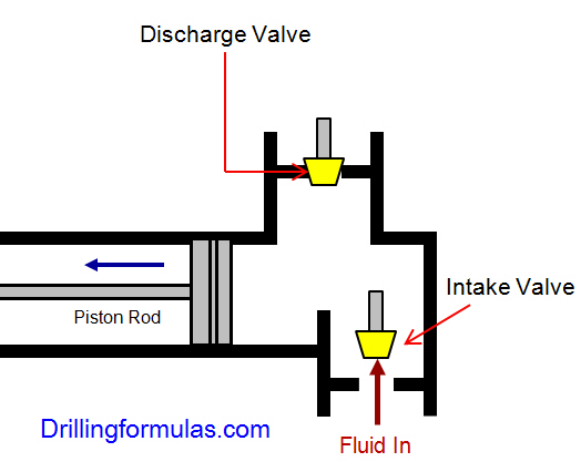
The duplex pumps (Figure 1) have two cylinders with double acting. It means that pistons move back and take in drilling mud through open intake valve and other sides of the same pistons, the pistons push mud out through the discharge valves.
When the piston rod is moved forward, one of intake valves is lift to allow fluid to come in and one of the discharge valve is pushed up therefore the drilling mud is pumped out of the pump (Figure 2).
On the other hand, when the piston rod is moved backward drilling fluid is still pumped. The other intake and discharge valve will be opened (Figure 3).
The triplex pumps have three cylinders with single acting. The pistons are moved back and pull in drilling mud through open intake valves. When the pistons are moved forward and the drilling fluid is pushed out through open discharge valves.
On the contrary when the piston rods are moved backward, the intake valve are opened allowing drilling fluid coming into the pump (Figure 6). This video below shows how a triplex mud pump works.
Because each pump has power rating limit as 1600 hp, this will limit capability of pump. It means that you cannot pump at high rate and high pressure over what the pump can do. Use of a small liner will increase discharge pressure however the flow rate is reduces. Conversely, if a bigger liner is used to deliver more flow rate, maximum pump pressure will decrease.
As you can see, you can have 7500 psi with 4.5” liner but the maximum flow rate is only 297 GPM. If the biggest size of liner (7.25”) is used, the pump pressure is only 3200 psi.
Finally, we hope that this article would give you more understanding about the general idea of drilling mud pumps. Please feel free to add more comments.

Mud pump is one of the most critical equipment on the rig; therefore personnel on the rig must have good understanding about it. We’ve tried to find the good training about it but it is very difficult to find until we’ve seen this VDO training and it is a fantastic VDO training about the basic of mud pumps used in the oilfield. Total length of this VDO is about thirteen minutes and it is worth to watch it. You will learn about it so quickly. Additionally, we also add the full detailed transcripts which will acceleate the learning curve of learners.
Powerful mud pumps pick up mud from the suction tank and circulate the mud down hole, out the bit and back to the surface. Although rigs usually have two mud pumps and sometimes three or four, normally they use only one at a time. The others are mainly used as backup just in case one fails. Sometimes however the rig crew may compound the pumps, that is, they may use three or four pumps at the same time to move large volumes of mud when required.
Rigs use one of two types of mud pumps, Triplex pumps or Duplex pumps. Triplex pumps have three pistons that move back-and-forth in liners. Duplex pumps have two pistons move back and forth in liners.
Triplex pumps have many advantages they weight 30% less than a duplex of equal horsepower or kilowatts. The lighter weight parts are easier to handle and therefore easier to maintain. The other advantages include;
• One of the more important advantages of triplex over duplex pumps, is that they can move large volumes of mud at the higher pressure is required for modern deep hole drilling.
Triplex pumps are gradually phasing out duplex units. In a triplex pump, the pistons discharge mud only when they move forward in the liner. Then, when they moved back they draw in mud on the same side of the piston. Because of this, they are also called “single acting.” Single acting triplex pumps, pump mud at a relatively high speeds. Input horsepower ranges from 220 to 2200 or 164 to 1641 kW. Large pumps can pump over 1100 gallons per minute, over 4000 L per minute. Some big pumps have a maximum rated pressure of over 7000 psi over 50,000 kPa with 5 inch/127 mm liners.
Here is a schematic of a triplex pump. It has three pistons each moving in its own liner. It also has three intake valves and three discharge valves. It also has a pulsation dampener in the discharge line.
Look at the piston at left, it has just completed pushing mud out of the liner through the open discharge valve. The piston is at its maximum point of forward travel. The other two pistons are at other positions in their travel and are also pumping mud. But for now, concentrate on the left one to understand how the pump works. The left piston has completed its backstroke drawing in mud through the open intake valve. As the piston moved back it instead of the intake valve off its seat and drew mud in. A strong spring holds the discharge above closed. The left piston has moved forward pushing mud through the now open discharge valve. A strong spring holds the intake valve closed. They left piston has completed its forward stroke they form the length of the liner completely discharging the mud from it. All three pistons work together to keep a continuous flow of mud coming into and out of the pump.
Crewmembers can change the liners and pistons. Not only can they replace worn out ones, they can also install different sizes. Generally they use large liners and pistons when the pump needs to move large volumes of mud at relatively low pressure. They use a small liners and pistons when the pump needs to move smaller volumes of mud at a relatively high pressure.
In a duplex pump, pistons discharge mud on one side of the piston and at the same time, take in mud on the other side. Notice the top piston and the liner. As the piston moves forward, it discharges mud on one side as it draws in mud on the other then as it moves back, it discharges mud on the other side and draws in mud on the side it at had earlier discharge it. Duplex pumps are therefore double acting.
Double acting pumps move more mud on a single stroke than a triplex. However, because of they are double acting they have a seal around the piston rod. This seal keeps them from moving as fast as a triplex. Input horsepower ranges from 190 to 1790 hp or from 142 to 1335 kW. The largest pumps maximum rated working pressure is about 5000 psi, almost 35,000 kPa with 6 inch/152 mm linings.
A mud pump has a fluid end, our end and intake and the discharge valves. The fluid end of the pump contains the pistons with liners which take in or discharge the fluid or mud. The pump pistons draw in mud through the intake valves and push mud out through the discharge valves.
The power end houses the large crankshaft and gear assembly that moves the piston assemblies on the fluid end. Pumps are powered by a pump motor. Large modern diesel/electric rigs use powerful electric motors to drive the pump. Mechanical rigs use chain drives or power bands (belts) from the rig’s engines and compounds to drive the pump.
A pulsation dampener connected to the pump’s discharge line smooths out surges created by the pistons as they discharge mud. This is a standard bladder type dampener. The bladder and the dampener body, separates pressurized nitrogen gas above from mud below. The bladder is made from synthetic rubber and is flexible. When mud discharge pressure presses against the bottom of the bladder, nitrogen pressure above the bladder resists it. This resistance smoothes out the surges of mud leaving the pump.
Here is the latest type of pulsation dampener, it does not have a bladder. It is a sphere about 4 feet or 1.2 m in diameter. It is built into the mud pump’s discharge line. The large chamber is form of mud. It has no moving parts so it does not need maintenance. The mud in the large volume sphere, absorbs this surges of mud leaving the pump.
A suction dampener smooths out the flow of mud entering into the pump. Crewmembers mount it on the triplex mud pump’s suction line. Inside the steel chamber is a air charged rubber bladder or diaphragm. The crew charges of the bladder about 10 to 15 psi/50 to 100 kPa. The suction dampener absorbs surges in the mud pump’s suction line caused by the fast-moving pump pistons. The pistons, constantly starts and stops the mud’s flow through the pump. At the other end of the charging line a suction pumps sends a smooth flow of mud to the pump’s intake. When the smooth flow meets the surging flow, the impact is absorbed by the dampener.
Workers always install a discharge pressure relief valve. They install it on the pump’s discharge side in or near the discharge line. If for some reason too much pressure builds up in the discharge line, perhaps the drill bit or annulus gets plugged, the relief valve opens. That opened above protects the mud pump and system damage from over pressure.
Some rig owners install a suction line relief valve. They install it on top of the suction line near the suction dampener. They mount it on top so that it won’t clog up with mud when the system is shut down. A suction relief valve protects the charging pump and the suction line dampener. A suction relief valve usually has a 2 inch or 50 mm seat opening. The installer normally adjusts it to 70 psi or 500 kPa relieving pressure. If both the suction and the discharged valves failed on the same side of the pump, high back flow or a pressure surge would occur. The high backflow could damage the charging pump or the suction line dampener. The discharge line is a high-pressure line through which the pump moves mud. From the discharge line, the mud goes through the stand pipe and rotary hose to the drill string equipment.

Power Zone Equipment reserves the right to modify this policy from time to time in order that it accurately reflects the legal and regulatory environment and our data collection principles. When material changes are made to this policy, Power Zone Equipment will post the revised policy on our website.

Drilling for oil and gas exploration is an involved and complicated operation requiring specialized machinery to accomplish. Drilling rig mud pumps are one of the fundamental pieces of machinery needed for a successful drilling operation. Waters International supplies drilling rig mud pumps and other specialized boring equipment for the oil and gas exploration industry.
A drilling rig mud pump is used to circulate drilling fluid or drilling mud into the bore hole to help cool, lubricate and clean the drill head as it bores into the ground. The drilling mud is also used to suspend and carry out drill cuttings from the drill head as it is brought in and out of the hole. This ensures that the drill does not clog and overheat, and makes the entire drilling operation smooth and safe.
Drilling rig mud pumps are usually reciprocating type pumps that basically work by drawing a fluid into a chamber or cylinder by the action of a piston, plunger or diaphragm, and then pushing it out to the needed direction through the use of one-way or check valves, resulting in the pulsed flow of the liquid in one direction. Ganging multiple pumps together increases the pump efficiency and provides a smoother liquid flow for better performance.
The action of the pump is used to draw out the drilling fluid from the bore hole, which is then filtered and cleared of impurities before being sent back in to cool and lubricate the drill head, and remove more drill cuttings. A failed pump will cause a disrupted flow of the drilling mud, which can cause the drill head to overheat or jam from cuttings and possibly even break. This can result in damage to the drilling equipment, and potentially cause injury to the drilling crew near the drilling rig.

What is a mud pump? A mud pump refers to a machine that transports mud or water and other flushing fluid into the borehole during drilling. Types of mud pumps are an important part of drilling equipment. In the commonly used positive circulation drilling, it is to send the surface flushing medium—clear water, mud, or polymer rinsing liquid to the bottom end of the drill bit through a high-pressure hose, faucet, and drill rod center hole under a certain pressure. Cool the drill bit, remove the cut debris and transport it to the surface.
The commonly used mud pump is a piston-type or a plunger type, and the crankshaft of the pump is driven by the power machine, and the crankshaft passes the crosshead to drive the piston or the plunger to reciprocate in the pump cylinder. Under the alternating action of the suction and discharge valves, the purpose of pumping and circulating the flushing liquid is achieved.
During operation, the power machine drives the main shaft and the crank that is fixed thereon by a transmission component such as a belt, a transmission shaft, and a gear. When the crank rotates counterclockwise from the horizontal position from left to right, the piston moves to the power end, the pressure in the liquid cylinder gradually decreases and a vacuum is formed, and the liquid in the suction pool is under the action of the liquid surface pressure, and the suction valve is opened to enter the liquid cylinder. Until the piston moves to the right stop. This working process is called the suction process of the pump.
After the crank completes the above suction process, it continues to rotate counterclockwise. At this time, the piston starts to move toward the hydraulic end (left side in the figure), and the liquid in the cylinder is squeezed. The pressure rises, the suction valve closes, and the discharge valve is closed. Top open, liquid enters the discharge pipe until the piston moves to the left stop. This process is called the pump discharge process. As the power machine continues to operate, the reciprocating pump continuously repeats the process of inhaling and discharging, and the liquid in the suction pool is continuously sent to the bottom of the well through the discharge pipe.

Mud pump is mainly used for geological drilling, geological engineering construction and foundation treatment of low and medium pressure grouting pump, etc. Mud pump is a machine that sends mud or water to the borehole during the drilling process. Mud pump is an important part of drilling equipment. All major businesses have mud pump parts for sale.
The main function of mud pump is to inject mud into the well along with the bit during the drilling process. It plays the role of cooling the drill bit, cleaning the drilling tool, fixing the well wall, driving drilling, and bringing the cuttings back to the surface after drilling.
In the commonly used positive circulation drilling, the mud pump sends the surface flushing medium-- clean water, mud or polymer flushing fluid to the end of the drill bit through the high pressure hose faucet and the center hole of the drill string under a certain pressure. Therefore, the purpose of cooling the drill bit and removing and conveying the cuttings to the surface is achieved.
Petroleum drilling mud pump is a kind of volumetric mud pump. Its basic working principle is that the volume of the sealed working chamber (mud pump cylinder liner) is periodically changed to convert the original mechanical energy into the pressure energy of the liquid to complete the operation.
The specific process relies on the reciprocating motion of the mud pump piston in the cylinder liner to make the volume of the working chamber in the cylinder liner change periodically. The mud pump cylinder liner is isolated from the outside world by means of a sealing device such as a seal ring, and communicates or closes with the pipeline through the pump valve (suction valve or discharge valve), which shows the importance of the mud pump cylinder liner. The three-cylinder mud pumps currently on the market are equipped with three cylinder sleeves.
Mud pumps can have two or three cylinders depending on the application and sometimes more than one pump can be run together when large amounts of mud are being circulated. A powerful motor is used to drive the pump.
Pulsation dampers on the discharge end of the pump smooth out the surges caused by the pistons discharging mud. Pumps can be designed for differing operating conditions by adjusting the size of the pistons and setting the discharge pressure.

hex pumps with six plungers. Triplex pumps are the most widely used because the pressure they provide is suitable for most applications and because of their simplicity and efficiency. Triplex pumps are susceptible to high vibration and noise during operation.

When choosing a size and type of mud pump for your drilling project, there are several factors to consider. These would include not only cost and size of pump that best fits your drilling rig, but also the diameter, depth and hole conditions you are drilling through. I know that this sounds like a lot to consider, but if you are set up the right way before the job starts, you will thank me later.
Recommended practice is to maintain a minimum of 100 to 150 feet per minute of uphole velocity for drill cuttings. Larger diameter wells for irrigation, agriculture or municipalities may violate this rule, because it may not be economically feasible to pump this much mud for the job. Uphole velocity is determined by the flow rate of the mud system, diameter of the borehole and the diameter of the drill pipe. There are many tools, including handbooks, rule of thumb, slide rule calculators and now apps on your handheld device, to calculate velocity. It is always good to remember the time it takes to get the cuttings off the bottom of the well. If you are drilling at 200 feet, then a 100-foot-per-minute velocity means that it would take two minutes to get the cuttings out of the hole. This is always a good reminder of what you are drilling through and how long ago it was that you drilled it. Ground conditions and rock formations are ever changing as you go deeper. Wouldn’t it be nice if they all remained the same?
Centrifugal-style mud pumps are very popular in our industry due to their size and weight, as well as flow rate capacity for an affordable price. There are many models and brands out there, and most of them are very good value. How does a centrifugal mud pump work? The rotation of the impeller accelerates the fluid into the volute or diffuser chamber. The added energy from the acceleration increases the velocity and pressure of the fluid. These pumps are known to be very inefficient. This means that it takes more energy to increase the flow and pressure of the fluid when compared to a piston-style pump. However, you have a significant advantage in flow rates from a centrifugal pump versus a piston pump. If you are drilling deeper wells with heavier cuttings, you will be forced at some point to use a piston-style mud pump. They have much higher efficiencies in transferring the input energy into flow and pressure, therefore resulting in much higher pressure capabilities.
Piston-style mud pumps utilize a piston or plunger that travels back and forth in a chamber known as a cylinder. These pumps are also called “positive displacement” pumps because they literally push the fluid forward. This fluid builds up pressure and forces a spring-loaded valve to open and allow the fluid to escape into the discharge piping of the pump and then down the borehole. Since the expansion process is much smaller (almost insignificant) compared to a centrifugal pump, there is much lower energy loss. Plunger-style pumps can develop upwards of 15,000 psi for well treatments and hydraulic fracturing. Centrifugal pumps, in comparison, usually operate below 300 psi. If you are comparing most drilling pumps, centrifugal pumps operate from 60 to 125 psi and piston pumps operate around 150 to 300 psi. There are many exceptions and special applications for drilling, but these numbers should cover 80 percent of all equipment operating out there.
The restriction of putting a piston-style mud pump onto drilling rigs has always been the physical size and weight to provide adequate flow and pressure to your drilling fluid. Because of this, the industry needed a new solution to this age-old issue.
As the senior design engineer for Ingersoll-Rand’s Deephole Drilling Business Unit, I had the distinct pleasure of working with him and incorporating his Centerline Mud Pump into our drilling rig platforms.
In the late ’90s — and perhaps even earlier — Ingersoll-Rand had tried several times to develop a hydraulic-driven mud pump that would last an acceptable life- and duty-cycle for a well drilling contractor. With all of our resources and design wisdom, we were unable to solve this problem. Not only did Miller provide a solution, thus saving the size and weight of a typical gear-driven mud pump, he also provided a new offering — a mono-cylinder mud pump. This double-acting piston pump provided as much mud flow and pressure as a standard 5 X 6 duplex pump with incredible size and weight savings.
The true innovation was providing the well driller a solution for their mud pump requirements that was the right size and weight to integrate into both existing and new drilling rigs. Regardless of drill rig manufacturer and hydraulic system design, Centerline has provided a mud pump integration on hundreds of customer’s drilling rigs. Both mono-cylinder and duplex-cylinder pumps can fit nicely on the deck, across the frame or even be configured for under-deck mounting. This would not be possible with conventional mud pump designs.
The second generation design for the Centerline Mud Pump is expected later this year, and I believe it will be a true game changer for this industry. It also will open up the application to many other industries that require a heavier-duty cycle for a piston pump application.

This rig features a Mission 4-by-5 centrifugal pump. Courtesy of Higgins Rig Co.Returning to the water well industry when I joined Schramm Inc. last year, I knew that expanding my mud pump knowledge was necessary to represent the company"s mud rotary drill line properly. One item new to me was the centrifugal mud pump. What was this pump that a number of drillers were using? I had been trained that a piston pump was the only pump of any ability.
As I traveled and questioned drillers, I found that opinions of the centrifugal pumps varied. "Best pump ever built," "What a piece of junk" and "Can"t drill more than 200 feet with a centrifugal" were typical of varying responses. Because different opinions had confused the issue, I concluded my discussions and restarted my education with a call to a centrifugal pump manufacturer. After that conversation, I went back to the field to continue my investigation.
For the past eight months, I have held many discussions and conducted field visits to understand the centrifugal pump. As a result, my factual investigation has clearly proved that the centrifugal pump has a place in mud rotary drilling. The fact also is clear that many drilling contractors do not understand the correct operational use of the pump. Following are the results of my work in the field.
High up-hole velocity - High pump flow (gpm) moves cuttings fast. This works well with lower viscosity muds - reducing mud expense, mixing time and creating shorter settling times.
Able to run a desander - The centrifugal"s high volume enables a desander to be operated off the pump discharge while drilling without adding a dedicated desander pump.
6. Sticky clays will stall a centrifugal pump"s flow. Be prepared to reduce your bit load in these conditions and increase your rpm if conditions allow. Yes, clays can be drilled with a centrifugal pump.
7. Centrifugal pumps cannot pump muds over 9.5 lbs./gal. Centrifugal pumps work best with a 9.0 lbs./gal. mud weight or less. High flow rate move cuttings, not heavy mud.
The goal of this article has been to increase awareness of the value of the centrifugal pump and its growing use. Although the centrifugal pump is not flawless, once its different operating techniques are understood, drilling programs are being enhanced with the use of this pump.
If you wish to learn more, please talk directly to centrifugal pump users. Feel free to call me at 314-909-8077 for a centrifugal pump user list. These drillers will gladly share their centrifugal pump experiences.

A comprehensive range of mud pumping, mixing, and processing equipment is designed to streamline many essential but time-consuming operational and maintenance procedures, improve operator safety and productivity, and reduce costly system downtime.
The 2,200-hp mud pump for offshore applications is a single-acting reciprocating triplex mud pump designed for high fluid flow rates, even at low operating speeds, and with a long stroke design. These features reduce the number of load reversals in critical components and increase the life of fluid end parts.
The pump’s critical components are strategically placed to make maintenance and inspection far easier and safer. The two-piece, quick-release piston rod lets you remove the piston without disturbing the liner, minimizing downtime when you’re replacing fluid parts.

The drilling industry has roots dating back to the Han Dynasty in China. Improvements in rig power and equipment design have allowed for many advances in the way crude oil and natural gas are extracted from the ground. Diesel/electric oil drilling rigs can now drill wells more than 4 miles in depth. Drilling fluid, also called drilling mud, is used to help transfer the dirt or drill cuttings from the action of the drilling bit back to the surface for disposal. Drill cuttings can vary in shape and size depending on the formation or design of the drill bit used in the process.
Watch the video below to see how the EDDY Pump outperforms traditional pumps when it comes to high solids and high viscosity materials commonly found on oil rigs.
The fluid is charged into high-pressure mud pumps which pump the drilling mud down the drill string and out through the bit nozzles cleaning the hole and lubricating the drill bit so the bit can cut efficiently through the formation. The bit is cooled by the fluid and moves up the space between the pipe and the hole which is called the annulus. The fluid imparts a thin, tough layer on the inside of the hole to protect against fluid loss which can cause differential sticking.
The fluid rises through the blowout preventers and down the flowline to the shale shakers. Shale shakers are equipped with fine screens that separate drill cutting particles as fine as 50-74 microns. Table salt is around 100 microns, so these are fine cuttings that are deposited into the half-round or cuttings catch tank. The drilling fluid is further cleaned with the hydro-cyclones and centrifuges and is pumped back to the mixing area of the mud tanks where the process repeats.
The drill cuttings contain a layer of drilling fluid on the surface of the cuttings. As the size of the drill cuttings gets smaller the surface area expands exponentially which can cause rheological property problems with the fluid. The fluid will dehydrate and may become too thick or viscous to pump so solids control and dilution are important to the entire drilling process.
One of the most expensive and troubling issues with drilling operations is the handling, processing, and circulation of drilling mud along with disposing of the unwanted drill cuttings. The drilling cuttings deposited in the half round tank and are typically removed with an excavator that must move the contents of the waste bin or roll-off box. The excavators are usually rented for this duty and the equipment charges can range from $200-300/day. Add in the cost for the day and night manpower and the real cost for a single excavator can be as much as $1800/day.
Using the excavator method explained above, the unloading of 50 barrels of drill cuttings from the half round can take as long as two hours. This task is mostly performed by the solids control technicians. The prime duty for the solids control technicians is to maintain the solids control equipment in good working order. This involves maintenance for the equipment, screen monitoring and changing, centrifuge adjustments, and retort testing to prepare a daily operational summary of the solids control program.
Offshore drilling rigs follow a similar process in which the mud is loaded into empty drums and held on the oil platform. When a certain number of filled drums is met, the drums are then loaded onto barges or vessels which take the drilling mud to the shore to unload and dispose of.
Oil field drilling operations produce a tremendous volume of drill cuttings that need both removal and management. In most cases, the site managers also need to separate the cuttings from the drilling fluids so they can reuse the fluids. Storing the cuttings provides a free source of stable fill material for finished wells, while other companies choose to send them off to specialty landfills. Regardless of the final destination or use for the cuttings, drilling and dredging operations must have the right high solids slurry pumps to move them for transport, storage, or on-site processing. Exploring the differences in the various drilling fluids, cutting complications, and processing options will reveal why the EDDY Pump is the best fit for the job.
The Eddy Pump is designed to move slurry with solid content as high as 70-80 % depending on the material. This is an ideal application for pumping drill cuttings. Drill cuttings from the primary shakers are typically 50% solids and 50% liquids. The Eddy Pump moves these fluids efficiently and because of the large volute chamber and the design of the geometric rotor, there is very little wear on the pump, ensuring long life and greatly reduced maintenance cost for the lifetime of the pump.
plumbed to sweep the bottom of the collection tank and the pump is recessed into a sump allowing for a relatively clean tank when the solids are removed. The Eddy Pump is sized to load a roll-off box in 10-12 minutes. The benefit is cuttings handling is quicker, easier, safer, and allows for pre-planning loading where the labor of the solids control technician is not monopolized by loading cuttings. Here, in the below image, we’re loading 4 waste roll-off bins which will allow the safe removal of cuttings without fear of the half-round catch tank running over.
Mud cleaning systems such as mud shaker pumps and bentonite slurry pumps move the material over screens and through dryers and centrifuges to retrieve even the finest bits of stone and silt. However, the pump operators must still get the raw slurry to the drill cuttings treatment area with a power main pump. Slurry pumps designed around the power of an Eddy current offer the best performance for transferring cuttings throughout a treatment system.
Options vary depending on whether the company plans to handle drill cuttings treatment on-site or transport the materials to a remote landfill or processing facility. If the plan is to deposit the cuttings in a landfill or a long-term storage container, it’s best to invest in a pump capable of depositing the material directly into transport vehicles. Most dredging operations rely on multiple expensive vacuum trucks, secondary pumps, and extra pieces of equipment.
Using an EDDY Pump will allow a project to eliminate the need for excavators/operators to load drill cuttings, substantially lowering both labor and heavy equipment costs. The EDDY Pump also allows a company to eliminate vacuum trucks once used for cleaning the mud system for displacing fluids. Since the pump transfers muds of all types at constant pressure and velocity throughout a system of practically any size, there’s little need for extra equipment for manual transfer or clean up on the dredge site.
The EDDY Pump can fill up a truck in only 10 minutes (compared to an hour) by using a mechanical means such as an excavator. For this reason, most companies can afford one piece of equipment that can replace half a dozen other units.
This application for the Eddy Pump has the potential to revolutionize the drilling industry. Moving the excavator out of the “back yard” (the area behind the rig from the living quarters) will make cuttings handling a breeze. Trucking can be easier scheduled during daylight hours saving on overtime and incidences of fatigued driving. Rig-site forklifts can move the roll-off boxes out of the staging area and into the pump loading area. The operator can save money on excavators rental, damages, and keep the technician operating the solids control equipment.
The EDDY Pump is ideal for drilling mud pump applications and can be connected directly onto the drilling rigs to pump the drilling mud at distances over a mile for disposal. This eliminates the need for costly vacuum trucks and also the manpower needed to mechanically move the drilling mud. The reasons why the EDDY Pump is capable of moving the drilling mud is due to the hydrodynamic principle that the pump creates, which is similar to the EDDY current of a tornado. This tornado motion allows for the higher viscosity and specific gravity pumping ability. This along with the large tolerance between the volute and the rotor allows for large objects like rock cuttings to pass through the pump without obstruction. The large tolerance of the EDDY Pump also enables the pump to last many times longer than centrifugal pumps without the need for extended downtime or replacement parts. The EDDY Pump is the lowest total life cycle pump on the market.

A mud pump (sometimes referred to as a mud drilling pump or drilling mud pump), is a reciprocating piston/plunger pump designed to circulate drilling fluid under high pressure (up to 7,500 psi or 52,000 kPa) down the drill string and back up the annulus. A mud pump is an important part of the equipment used for oil well drilling.
Mud pumps can be divided into single-acting pump and double-acting pump according to the completion times of the suction and drainage acting in one cycle of the piston"s reciprocating motion.
Mud pumps come in a variety of sizes and configurations but for the typical petroleum drilling rig, the triplex (three piston/plunger) mud pump is used. Duplex mud pumps (two piston/plungers) have generally been replaced by the triplex pump, but are still common in developing countries. Two later developments are the hex pump with six vertical pistons/plungers, and various quintuplexes with five horizontal piston/plungers. The advantages that these new pumps have over convention triplex pumps is a lower mud noise which assists with better measurement while drilling (MWD) and logging while drilling (LWD) decoding.
The fluid end produces the pumping process with valves, pistons, and liners. Because these components are high-wear items, modern pumps are designed to allow quick replacement of these parts.
To reduce severe vibration caused by the pumping process, these pumps incorporate both a suction and discharge pulsation dampener. These are connected to the inlet and outlet of the fluid end.
The pressure of the pump depends on the depth of the drilling hole, the resistance of flushing fluid (drilling fluid) through the channel, as well as the nature of the conveying drilling fluid. The deeper the drilling hole and the greater the pipeline resistance, the higher the pressure needed.
With the changes of drilling hole diameter and depth, the displacement of the pump can be adjusted accordingly. In the mud pump mechanism, the gearbox or hydraulic motor is equipped to adjust its speed and displacement. In order to accurately measure the changes in pressure and displacement, a flow meter and pressure gauge are installed in the mud pump.
The construction department should have a special maintenance worker that is responsible for the maintenance and repair of the machine. Mud pumps and other mechanical equipment should be inspected and maintained on a scheduled and timely basis to find and address problems ahead of time, in order to avoid unscheduled shutdown. The worker should attend to the size of the sediment particles; if large particles are found, the mud pump parts should be checked frequently for wear, to see if they need to be repaired or replaced. The wearing parts for mud pumps include pump casing, bearings, impeller, piston, liner, etc. Advanced anti-wear measures should be adopted to increase the service life of the wearing parts, which can reduce the investment cost of the project, and improve production efficiency. At the same time, wearing parts and other mud pump parts should be repaired rather than replaced when possible.

A properly serviced pulsation dampener is critical for your mud pumps’ efficiency, safety, and performance. Unfortunately, there aren’t many resources available to educate personnel on executing safe and effective servicing procedures. Please review the following steps with your personnel for safe pulsation dampener maintenance.

abstractNote = {Based on extensive research, development, and field testing of mud pumps and accessory equipment, this book offers cost-saving methods in operation and maintenance of triplex and duplex pumps. It covers practical engineering concerns such as pressure losses from friction in the piping and inertia in the drilling mud; suction dampeners in pump operation; charging the suction pipe for greater efficiency and smoother operation; hydraulic and mechanical knocking; hydraulic pressure losses; discharge lines.},


 8613371530291