
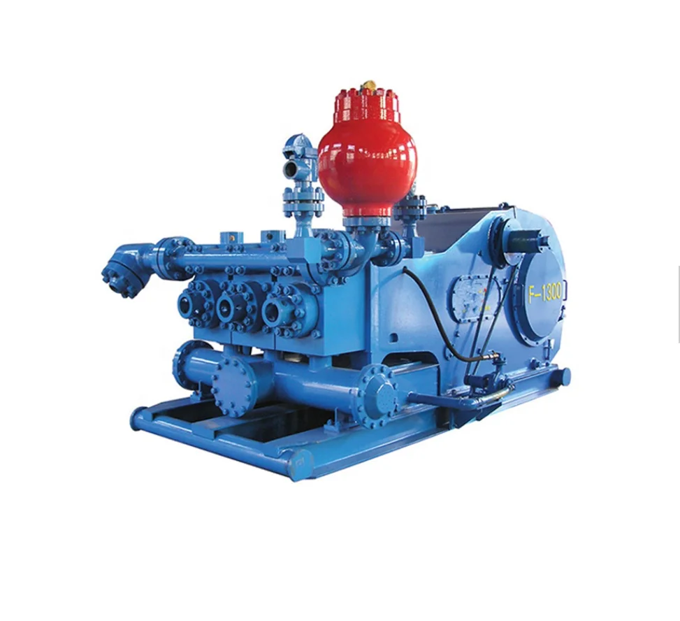
nabors drilling mud pump free sample
Managed Pressure Drilling (MPD) is an adaptive process used to more precisely control the annular pressure profile throughout the wellbore while drilling. Converting conventional atmospheric drilling to a closed circulating loop system enables the driller to optimize mud weight and rate of penetration (ROP), more quickly detect influx and fluid loss, and discriminate wellbore ballooning and breathing. This results in lower mud product cost, less stuck pipe, and potentially fewer casing strings.
The MPD process is executed by controlling flow conditions to maintain bottom-hole pressure according to a modeled pore pressure and fracture gradient drilling window. While the benefits of conventional MPD techniques are well known offshore, the economics of engineering, mobilization and rig-up, and additional specialized personnel requirements are not supported in cost-sensitive drilling programs such as unconventional land drilling.
Nabors’ fit-for-purpose MPD equipment and integrated rig services enables a new concept to leverage today’s advanced land rig infrastructure including drives, manifolds, tanks, pumps, and gas handling equipment. Engineering and integrating MPD capabilities into the rig with unique automated workflows unlocks advantages in capital requirements, eliminates the need for pre-job surveys and engineering, and minimizes high mobilization and rig-up costs.
Through the advanced integration and automation of MPD services, the need for third-party service providers is also eliminated. Benefits include increased safety, less HSE exposure, lower cost, reduced pad footprint, more efficient rig moves, and more transparent performance analytics. For all of these reasons, scalability of MPD services is now more cost-effective for land drilling operations.

Jan. 25, 2023 -- Nabors’ recent acquisition of the engineering technology firm, MindMesh, includes the downhole simulation and modeling technologies that the MindMesh team has developed. Additionally, MindMesh co-founder and Chief Technology Officer Raju Gandikota...

This application claims priority under 35 U.S.C. § 119(e) to U.S. Provisional Patent Application No. 62/719,203 entitled “Systems and Methods of Conducting Subterranean Drilling Operations,” by Brian Ellis et al., filed Aug. 17, 2018, which is assigned to the current assignee hereof and incorporated herein by reference in its entirety.
The present disclosure relates to systems and methods of conducting subterranean drilling operations, and more particularly to systems and methods of analyzing components of gas during drilling operations.
Drilling operations in subterranean formations typically involves removal of cuttings from the subterranean formation and circulation thereof to the surface. The cuttings are carried to the surface by drilling fluid and can include gases, vapors, hydrocarbons, and other materials from within the subterranean formation. The drilling industry continues to demand improvements in drilling operations and efficiencies. As such, improvement in qualitative analysis of the drilling fluid is continuously demanded by the industry.
Unless otherwise defined, all technical and scientific terms used herein have the same meaning as commonly understood by one of ordinary skill in the art to which this invention belongs. The materials, methods, and examples are illustrative only and not intended to be limiting. To the extent not described herein, many details regarding specific materials and processing acts are conventional and may be found in textbooks and other sources within the drilling arts.
Generally, a system for conducting a subterranean drilling operation can include a chromatography device adapted to detect a composition of a gas in the drilling operation. For example, in drilling operations a drill string is lowered into a wellbore and advanced into a subterranean formation. Gases, vapors, and other compositions of material are removed from the subterranean formation and can circulate to the surface of the wellbore where the chromatography device can measure the composition of the gas.
In a particular embodiment, the chromatography device can be disposed in series with a flare line extending from a separating device, such as for example, a mud gas separator or a shaker, to a flare for burn off. In another embodiment, the chromatography device can be disposed in parallel with the flare line.
A method for conducting subterranean drilling operations can include detecting a composition of gas, sensing a mass flowrate of the gas, and calculating a volumetric flow rate of components of the gas using at least one of the detected composition of the gas and the mass flowrate of the gas.
As the BHA 112 advances into the subterranean formation 106, cuttings, gases, vapors, and other materials utilized in drilling, including drilling mud, are circulated through the wellbore 104 in a direction which can generally occur along arrow 114. In a particular embodiment, circulation can be driven at least in part by wellbore pressure management. For example, the drill rig 102 can include mud pumps (not illustrated) adapted to deliver drilling mud into the wellbore 104 to the BHA 112. Pressurized drilling mud can then carry the circulated materials from the BHA 112 location to a surface 116 of the wellbore 104. As the wellbore 104 advances deeper into the subterranean formation 104, the distance of travel between the BHA 112 and the surface 116 of the wellbore 104 can increase.
A drive unit, such as a top drive 120, can control the drill string"s 110 advance into the wellbore 104. During periods of drilling, the top drive 120 (or other known drive unit) can advance the drill string 110 into the wellbore 104.
A flow line 122 extending from the wellbore 104, RCD 118, other intermediary terminal, or a combination thereof can carry flow of wellbore fluid (including for example the drilling mud, cuttings, gases, and vapors) to a separating device 124 adapted to separate at least gases from the wellbore fluid. In an embodiment, the separating device 124 can include a mud gas separator. In a particular embodiment, the mud gas separator can include a plurality of baffles adapted to agitate the wellbore fluid and release gas therefrom. In another embodiment, the separating device 124 can include a shaker having an active agitating mechanism such as a stirrer, to separate gas from the wellbore fluid.
Gas released from the wellbore fluid can travel along a flow line 126 (sometimes referred to as a flare line) to a detection area 128 for analyzation while solids and other non-gases in the wellbore fluid can pass through a flow line 130 to a further separating device 132 which can empty into a mud storage area 134 or directly to the mud storage area 134. Gas can pass through the flow line 126 to the detection area 128 on its way to a flare 136 for burn off. In the illustrated embodiment, the detection area 128 is in series with the flare 136.
In an embodiment, the system 100 can include a pump 146 disposed between the separating device 124 and the chromatography device 142. The pump 146 can be adapted to bias gas to the chromatography device 142. In the illustrated embodiment, the pump 146 is disposed on an auxiliary line between the flow line 126 and the chromatography device 142. In another embodiment, the pump 146 can be disposed along the flow line 126. In yet another embodiment, the chromatography device 142 can be disposed between the pump 146 and the flow line 126.
Volumetric flow rates of components of the gas can include calculated volumetric flow rates of individual components of the gas. Thus, for example, the logic device 148 can determine individual volumetric flow rates or mass flow rates of each gas exiting the wellbore 104. In such a manner, the logic device 148 can provide quantitative gas analysis previously unavailable or lacking during drilling operations.
The user, such as a driller, can view the display apparatus 150 to determine composition of the subterranean formation 106 (FIG. 1). More particularly, the user can view the display apparatus 150 to determine the gas composition of the subterranean formation 106. The user can adjust one or more drilling parameters such as for example fluid flow rate within the wellbore, drilling angle or operation of the BHA 112, speed or torque of the top drive 120, or any combination thereof in response to the composition of gases in the subterranean formation 106. In such a manner, the user can take action to control the wellbore, increase drilling efficiency, alter the wellbore plan, or otherwise adjust the wellbore in a desired manner. For example, when drilling certain subterranean formations 106, the presence of certain gases at certain volumetric ratios can indicate a specific action should be taken by the driller. Through detailed analysis provided by the system 100, the driller can better predict and control the drilling operation. Further, the driller can identify different zones of the subterranean formation, such as fracking zones, based on the presence of certain gases at certain volumetric ratios.
In certain embodiments, the logic device 148 can be coupled with, or part of, an autonomous system adapted to adjust one or more parameters of the wellbore in response to the volumetric mass flowrate of components of the gases from the wellbore 104. For example, the autonomous system can be preprogrammed or taught to recognize conditions of the wellbore 104 or subterranean formation 106 based on volumetric flowrates of components of the gases therefrom. Once the autonomous system detects thresholds of volumetric flowrate outside of operating limits, the system can adjust one or more parameters of the wellbore 104 for desired drilling efficiency, safety, or a combination thereof.
As illustrated in FIG. 3, in an embodiment the system 100 can include a gas filtration system 152, a gas density sensor 154, a temperature sensor 156, or any combination thereof. In non-illustrated embodiments, the system 100 can further include an automated cuttings cleaning and lithology logging system optionally including XFR camera logging. In a particular embodiment, the gas filtration system 152 can be disposed between the separating device 124 and the gas density sensor 154, sensor 144, or both. In an embodiment, the gas density sensor 154, temperature sensor 156, or a combination thereof can be distinct from the sensor 144. In another embodiment, the gas density sensor 154, temperature sensor 156, CDT mud sensor system 158, or a combination thereof can be the same or part of sensor 144.
Skilled artisans will understand after reading the entire disclosure that certain embodiments described herein can offer quantitative analysis of the wellbore condition. Such quantitative analysis has been lacking in the drilling industry and is required today for advanced drilling techniques in dangerous and hostile drilling environments where even small deviations can result in economic or efficiency losses. Moreover, simply detecting the presence of gases without quantitatively analyzing such gases is insufficient for modern equipment and processes capable of advanced adaptation to advanced wellbore monitoring conditions.
Embodiments of the present invention are described generally herein in relation to drilling directional wells or unconventional wells, but it should be understood, however, that the methods and the apparatuses described may be equally applicable to other drilling environments. Further, while the descriptions and figures herein show a land-based drilling rig, one or more aspects of the present disclosure are applicable or readily adaptable to any type of drilling rig, such as jack- up rigs, semisubmersibles, drill ships, coil tubing rigs, well service rigs adapted for drilling and/or re-entry operations, and casing drilling rigs, among others within the scope of the present disclosure.
Embodiment 1. A system for conducting subterranean drilling operations comprising: a chromatography device adapted to detect a composition of gas; a sensor adapted to measure a mass flowrate of the gas; and a logic device adapted to calculate volumetric mass flow rates of components of the gas utilizing the mass flowrate from the sensor and the composition from the chromatography device.
Embodiment 3. The system of embodiment 1, wherein the system further comprising: a gas dryer disposed between the mud gas separator and the chromatography device.
Embodiment 8. The system of embodiment 1, further comprising: a pump disposed between a mud gas separator and the chromatography device, wherein the pump is adapted to bias gas to the chromatography device.
Embodiment 17. A method for conducting subterranean drilling operations comprising: detecting a composition of a gas; sensing a mass flowrate of the gas; calculating volumetric mass flowrates of a plurality of components of the gas using the detected composition of the gas and the mass flowrate of the gas.
Embodiment 21. The method of embodiment 20, wherein the sample of gas comprises less than 50% of the volume of gas exiting the mud gas separator, less than 40% of the volume of gas exiting the mud gas separator, less than 30% of the volume of gas exiting the mud gas separator, less than 20% of the volume of gas exiting the mud gas separator, less than 10% of the volume of gas exiting the mud gas separator, or less than 5% of the volume of gas exiting the mud gas separator.
Embodiment 26. The method of embodiment 25, wherein retrofitting the components to the existing drilling rig is performed by coupling the components with a flare line of the drilling rig.
Embodiment 43. A system for conducting subterranean drilling operations comprising: a logic device adapted to calculate volumetric mass flow rates of components of a gas from a wellbore; and at least one of: a user display adapted to display the calculated volumetric mass flow rate to a user; an autonomous system adapted to autonomously adjust a parameter of a wellbore condition in response to the calculated volumetric mass flow rate; or a combination thereof.

Fully Articulated Ramp Extension For Pipe Handling Apparatus, U.S. Pat. No. 5,122,023; Method and Apparatus for Controlling the Transfer of Tubular Members Into a Shelter, U.S. Pat. No. 5,072,656; Mobile Drilling Rig for closely Spaced Well Centers, U.S. Pat. No. 5,109,934; and Harness method and Apparatus, U.S. Pat. No. 5,125,857.
The present invention relates generally to drilling rigs and, more particularly, to a self-propelled well servicing and workover rig for use in harsh arctic environments.
Workovers can be accomplished by erecting a freestanding derrick over the well, performing the workover, and then disassembling the derrick. However, workovers typically require much less time to complete than the initial drilling operation. Therefore, assembling and disassembling a derrick to perform a workover introduces an inefficiency that may significantly offset the benefits of the workover. To overcome this inefficiency, portable drilling rigs, commonly called "workover rigs," typically perform workovers. These portable drilling rigs include a derrick that is mounted on a trailer or self-propelled chassis. The derrick may be pivoted from a portable position, where the derrick rests horizontally on the rig, to a working position, where the derrick is fixed in a substantially upright position over the well.
Workovers require much equipment in addition to the portable derrick. Many downhole operations are accomplished using a pipe string that is introduced into the well from the derrick. The pipe string is made up of a series of short interconnected pipe sections. In a drilling operation, for instance, a bit is placed on the lower end of the pipe string, and the pipe string is rotated from above the earth"s surface by a suitable rotary drive mechanism. As the bit bores deeper, additional pipe sections must be connected to the pipe string. Moreover, in order to satisfactorily form the bore, the cuttings produced as the bit bores deeper must be carried out of the well hole. For this purpose, a mud slurry is pumped downwardly through the pipe to gather the cuttings, and then pumped upwardly around the annulus between the pipe and the well hole to remove the cuttings. Therefore, a supply of tools, pipe, and mud should be readily available to the drillers performing the workover.
Supplying tools, pipe, and mud to a portable drilling rig in warm climates presents relatively few problems. The pipe is simply arranged in racks adjacent the derrick. As more pipe is needed, operators load pipe onto a suitable conveyor and guide the pipe toward the derrick along a ramp, typically referred to as a beaver slide, for delivery to the derrick. Similarly, equipment for mixing a suitable slurry of mud may be positioned outside on the ground adjacent the derrick. Then, it is a relatively simple procedure for operators to arrange pumps and piping for pumping mud into the well through the drill string and out of the well through the well annulus. Moreover, when changing a drill bit, or withdrawing pipe from the well for any other reason, the detached sections of pipe may be simply removed from the derrick and placed in a convenient location on racks on the ground.
However, portable drilling rigs of this type present distinct disadvantages when used in a cold environment. For example, the rigs offer no shelter to the workmen. Furthermore, the pipe may become damaged or difficult to manage because it is not protected from the environment. In frigid environments, ice may form on the threads of pipe stored outside and, thus, cause the threads to deform during connection unless the ice is removed. To overcome these problems, winterized portable drilling rigs have been developed. On these winterized rigs, portions of the chassis carrying equipment for use by the workmen are enclosed in a housing which may be thought of as a vehicle body.
In addition to the winterizing of the portable derricks themselves, pipe shelters and mud/utility support modules have been developed. A pipe shelter essentially includes a trailer having a number of pipe racks for carrying the pipe to be used on the derrick, and a pipe conveyor for transferring pipe up the beaver slide to the derrick. These apparatus are enclosed by a winterized housing which has a door therein for receiving additional loads of pipe. In cold climates, it is important to keep the pipe warm so that new sections of pipe easily interconnect with pipe in the pipe string.
In a similar fashion, the mud module includes the necessary mud producing equipment, such as water and mud tanks, which is mounted on a trailer chassis. A winterized housing encloses the equipment on the trailer chassis, and usually includes a passageway for interconnecting the mud module to the portable drilling module. Thus, once the mud module and the pipe shelter are interconnected with the portable drilling module, the winterized drilling rig protects the workmen and the necessary support equipment from the environment.
Unfortunately, these winterized rigs still exhibit certain disadvantages. For example, at -50°F., it is important that the winterized shelters of the various modules of the portable drilling rig protect the workmen in as many phases of normal operation as possible. As one example, a pipe shelter includes a door for loading and unloading pipe. If this door remains open too long, the heat within the shelter will rapidly escape, thus leaving the workmen inside exposed to frigid temperatures.
In accordance with one aspect of the present invention, there is provided a drilling apparatus which includes a wheeled carrier having a derrick disposed thereon. The derrick is adapted to be positioned over a well and to control insertion and retraction of at least 8000 feet of pipe sections. A shelter is also disposed on the carrier. The shelter is adapted to extend from the well to a preselected height on the derrick and thereby substantially surround a portion of the derrick.
In accordance with another aspect of the present invention, there is provided a drilling apparatus which includes a wheeled carrier having a drill floor coupled thereto or integral therewith. A derrick is also disposed on the carrier and adapted to be positioned over a well adjacent the drill floor. A shelter is disposed on the carrier and substantially encloses the carrier and the drill floor. Furthermore, a plurality of hydraulically operated feet are disposed on the carrier. The feet are extendable into contact with the ground for working and retractable for transportation. A selected portion of the feet are located beneath the drill floor and are encompassed by the shelter in both the extended and retracted positions.
FIG. 3 illustrates a detailed side view of the lower portion of the portable drilling module in a working mode in accordance with the present invention;
Turning now to the drawings and referring initially to FIGS. 1 and 2, a self-propelled drilling module is illustrated and generally designated by the reference numeral 10. Generally speaking, the drilling module 10 operates in two different modes: a transportation mode and a working mode. FIG. 1 illustrates the module 10 in its transportation mode, and FIG. 2 illustrates the module 10 in its working mode. The module 10 is mounted on a carrier 12 so that it can be transported from one worksite to another with a minimum of tear-down and reconstruction. To position the drilling module 10 once it reaches a worksite, the operator reverses the carrier 12 and backs over the well. Preferably, operators use a crosshair (not shown) mounted at the rear of the carrier 12 to accurately position the module 10 over the center of the well.
Typically, the derrick 36 is not raised to its working position until the drilling module 10 has been properly positioned with respect to the well and the feet 14-22 have been lowered and locked. Preferably, the derrick 36 is of a type available from KREMCO of Edmonton, Alberta, Canada, having a static hook load capacity of 350,000 pounds and a racking capacity of 12,000" of 31/2" drill pipe or 10,000" of 51/2" tubing.
As illustrated, the drilling module 10 is mounted on a self-propelled carrier 12 so that it can easily move from worksite to worksite. Preferably, the carrier 12 is a model K1250 5-axle back-in type carrier available from KREMCO. The driver of the carrier 12 resides in an operating cab 48 at one end of the carrier 12, and the portion of the carrier 12 to the rear of the cab 48 carries equipment for use in workovers.
The engines 50 and 52 also power a mud pump 58, a drawworks 60, and a rotary table 69. Preferably, the mud pump 58 is of a type available from USS Oilwell Suppliers Co. of Houston, Tex., and the drawworks 60 is of a type available from Midcontinent Supply Co. of Fort Worth, Tex. When the module 10 is in its working mode, the engines 50 and 52 provide power to the mud pump 58, to the drawworks 60, and to the rotary table 69 in a manner conventionally known in the art.
The module 10 may also house other equipment useful for workover operations. As illustrated the module 10 houses a generator set 68. While the generator set 68 is typically used to power only the lights and a few other electrical accessories, it is preferably sized so that it can provide all of the power to the drilling module 10 as well any other associated modules, such as a mud module and pipe shelter. Preferably, the generator set 68 includes a model 3408 engine coupled to a 365 kW a.c. generator. In addition, the module 10 advantageously houses an accumulator 70 for use with blow out preventors, and the module also includes a choke manifold and a rotary crankcase 71.
Just below the drill floor 74, an opening is provided in the panels 72 and referred to herein as a pipe transfer access 76. The pipe transfer access 76 couples to a pipe shelter 78, as illustrated in FIG. 7, so that pipe for the pipe string can be transferred between the drilling module 10 and the pipe shelter. Preferably, the pipe shelter 78 corresponds to the pipe shelter described in U.S. Pat. No. 5,072,656. In conjunction therewith, the drill floor 74 preferably includes an articulatable pipe ramp extension 80 for facilitating transfer of pipe between the module 10 and the pipe shelter. Preferably, the pipe ramp extension 80 corresponds to the pipe ramp extension described in U.S. Pat. No. 5,122,023.
The panels 74 provide a second opening in the module which is referred to herein as a passageway 82. The passageway 82 couples the module 10 to a mud module 84 so that workmen can move between the module 10 and the mud module 84 while remaining warm and sheltered. Preferably, the mud module ,84 corresponds to the mud module described in U.S. Pat. NO. 5,072,656. This application also describes a preferred orientation for the modules 10, 78 and 84 with respect to the wells 89.
The invention relates generally to offshore drilling systems which are employed for drilling subsea wells. More particularly, the invention relates to an offshore drilling system which maintains a dual pressure gradient, one pressure gradient above the well and another pressure gradient in the well, during a drilling operation.
Deep water drilling from a floating vessel typically involves the use of a large- diameter marine riser, e.g. a 21 -inch marine riser, to connect the floating vessel"s surface equipment to a blowout preventer stack on a subsea wellhead. The floating vessel may be moored or dynamically positioned at the drill site. However, dynamically-positioned drilling vessels are predominantly used in deep water drilling. The primary functions of the marine riser are to guide the drill string and other tools from the floating vessel to the subsea wellhead and to conduct drilling fluid and earth-cuttings from a subsea well to the floating vessel. The marine riser is made up of multiple riser joints, which are special casings with coupling devices that allow them to be interconnected to form a tubular passage for receiving drilling tools and conducting drilling fluid. The lower end of the riser is normally releasably latched to the blowout preventer stack, which usually includes a flexible joint that permits the riser to angularly deflect as the floating vessel moves laterally from directly over the well. The upper end of the riser includes a telescopic joint that compensates for the heave of the floating vessel. The telescopic joint is secured to a drilling rig on the floating vessel via cables that are reeved to sheaves on riser tensioners adjacent the rig"s moon pool. The riser tensioners are arranged to maintain an upward pull on the riser. This upward pull prevents the riser from buckling under its own weight, which can be quite substantial for a riser extending over several hundred feet. The riser tensioners are
The maximum practical water depth for current drilling practices with a large diameter marine riser is approximately 7,000 feet. As the need to add to energy reserves increases, the frontiers of energy exploration are being pushed into ever deeper waters, thus making the development of drilling techniques for ever deeper waters increasingly more important. However, several aspects of current drilling practices with a conventional marine riser inherently limit deep water drilling to water depths less than approximately 7,000 feet. The first limiting factor is the severe weight and space penalties imposed on a floating vessel as water depth increases. In deep water drilling, the drilling fluid or mud volume in the riser constitutes a majority of the total mud circulation system and increases with increasing water depth. The capacity of the 21 -inch marine riser is approximately 400 barrels for every 1,000 feet. It has been estimated that the weight attributed to the marine riser and mud volume for a rig drilling at a water depth of 6,000 feet is 1,000 to 1,500 tons. As can be appreciated, the weight and space requirements for a drilling rig that can support the large volumes of fluids required for circulation and the number of riser joints required to reach the seafloor prohibit the use of the 21 -inch riser, or any other large-diameter riser, for drilling at extreme water depths using the existing offshore drilling fleet.
water waves and can result in high levels of energy being imparted on the drilling vessel and the riser, especially when the bottom end of the riser is disconnected from the blowout preventer stack. The dynamic stresses due to the interaction between the heave of the drilling vessel and the riser can result in high compression waves that may exceed the capacity of the riser.
In water depths 6,000 feet and greater, the 21 -in riser is flexible enough that angular and lateral deflections over the entire length of the riser will occur due to the water currents acting on the riser. Therefore, in order to keep the riser deflections within acceptable limits during drilling operations, tight station keeping is required. Frequently, the water currents are severe enough that station keeping is not sufficient to permit drilling operations to continue. Occasionally, water currents are so severe that the riser must be disconnected from the blowout preventer stack to avoid damage or permanent deformation. To prevent frequent disconnection of the riser, an expensive fairing may have to be deployed or additional tension applied to the riser. From an operational standpoint, a fairing is not desirable because it is heavy and difficult to install and disconnect. On the other hand, additional riser tensioners may over-stress the riser and impose even greater loads on the drilling vessel.
A third limiting factor is the difficulty of retrieving the riser in the event of a storm. Based on the large forces that the riser and the drilling vessel are already subjected to, it is reasonable to conclude that neither the riser nor the drilling vessel would be capable of sustaining the loads imposed by a hurricane. In such a condition, if the drilling vessel is a dynamically positioned type, the drilling vessel will attempt to evade the storm. Storm evasion would be impossible with 10,000 feet of riser hanging from the drilling vessel. Thus, in such a situation, the riser would have to be pulled up entirely.
In addition, before disconnecting the riser from the blowout preventer stack, operations must take place to condition the well so that the well may be safely abandoned. This is required because the well depends on the hydrostatic pressure of the mud column extending from the top end of the riser to the bottom of the well to
overcome the pore pressures of the formation. When the mud column in the riser is removed, the hydrostatic pressure gradient is significantly reduced and may not be sufficient to prevent formation fluid influx into the well. Operations to contain well pressure may include setting a plug, such as a storm packer, in the well and closing the blind ram in the blowout preventer stack.
After the storm, the drilling vessel would return to the drill site and deploy the riser to reconnect and resume drilling. In locations like Gulf of Mexico where the average annual number of hurricanes is 2.8 and the maximum warning time of an approaching hurricane is 72 hours, it would be necessary to disconnect and retrieve the riser every time there is a threat of hurricane in the vicinity of the drilling location. This, of course, would translate to huge financial losses to the well operator.
A fourth limiting factor, relates to emergency disconnects such as when a dynamically positioned drilling vessel experiences a drive off. A drive off is a condition when a floating drilling vessel loses station keeping capability, loses power, is in imminent danger of colliding with another marine vessel or object, or experiences other conditions requiring rapid evacuation from the drilling location. As in the case of the storm disconnect, well operations are required to condition the well for abandoning. However, there is usually insufficient time in a drive off to perform all of the necessary safe abandonment procedures. Typically, there is only sufficient time to hang off the drill string from the pipe/hanging rams and close the shear/blind rams in the blowout preventer before disconnecting the riser from the blowout preventer stack.
The well hydrostatic pressure gradient derived from the riser height is trapped below the closed blind rams when the riser is disconnected. Thus, the only barrier to the influx of formation fluid into the well is the closed blind rams since the column of mud below the blind rams is insufficient to prevent influx of formation fluid into the well. Prudent drilling operations require two independent barriers to prevent loss of well control. When the riser is disconnected from the blowout preventer stack, large volumes of mud will be dumped onto the seafloor. This is undesirable from both an economic and environmental standpoint.
A fifth limiting factor relates to marginal well control and the need for numerous casing points. In any drilling operation, it is important to control the influx of formation fluid from subsurface formations into the well to prevent blowout. Well control procedures typically involve maintaining the hydrostatic pressure of the drilling fluid column above the "open hole" formation pore pressure but, at the same time, not above the formation fracture pressure. In drilling the initial section of the well, the hydrostatic pressure is maintained using seawater as the drilling fluid with the drilling returns discharged onto the seafloor. This is possible because the pore pressures of the formations near the seafloor are close to the seawater hydrostatic pressure at the seafloor. While drilling the initial section of the well with seawater, formations having pore pressures greater than the seawater hydrostatic pressure may be encountered. In such situations, formation fluids may flow freely into the well. This uncontrolled flow of formation fluids into the well may be so great as to cause washouts of the drilled hole and, possibly, destroy the drilling location. To prevent formation fluid flow into the well, the initial section of the well may be drilled with weighted drilling fluids. However, the current practice of discharging fluid to the seafloor while drilling the initial section of the well does not make this option very attractive. This is because the large volumes of drilling fluids dumped onto the seafloor are not recovered. Large volumes of unrecovered weighted drilling fluids are expensive and, possibly, environmentally undesirable.
After the initial section of the well is drilled to an acceptable depth, using either seawater or weighted drilling fluid, a conductor casing string with a wellhead is run and cemented in place. This is followed by running a blowout preventer stack and marine riser to the seafloor to permit drilling fluid circulation from the drilling vessel to the well and back to the drilling vessel in the usual manner.
These sediments are significantly influenced by the overlying body of water and the circulating mud column need only be slightly denser than seawater to fracture the formation. Fortunately, because of the higher bulk density of the rock, the fracture pressure rapidly increases with the depth of penetration below the seafloor and will present a less serious problem after the first few thousand feet are drilled. However, abnormally high pore pressures which are routinely encountered up to 2,000 feet below the seafloor continue to present a problem both when drilling the initial section of the well with seawater and when drilling beyond the initial section of the well with seawater or weighted drilling fluid. The challenge then becomes balancing the internal pressures of the formation with the hydrostatic pressure of the mud column while continuing drilling of the well. The current practice is to progressively run and cement casings, the next inside the previous, into the hole to protect the "open hole" sections possessing insufficient fracture pressure while allowing weighted drilling fluids to be used to overcome formation pore pressures. It is important that the well be completed with the largest practical casing through the production zone to allow production rates that will justify the high-cost of deep-water developments. Production rates exceeding 10,000 barrels per day are common for deep-water developments, and too small a production casing would limit the productivity of the well, making it uneconomical to complete. The number of casings run into the hole is significantly affected by water depth.
The multiple casings needed to protect the "open hole" while providing the largest practical casing through the production zone requires that the surface hole at the seafloor be larger. A larger surface hole in turn requires a larger subsea wellhead and blowout preventer stack and a larger blowout preventer stack requires a larger marine riser. With a larger riser, more mud is required to fill the riser and a larger drilling vessel is required to carry the mud and support the riser. This cycle repeats itself as water depth increases.
It has been identified that the key to breaking this cycle lies in reducing the hydrostatic pressure of the mud in the riser to that of a column of seawater and providing mud with sufficient weight in the well to maintain well control. Various concepts have
been presented in the past for achieving this feat; however, none of these concepts known in the prior art have gained commercial acceptance for drilling in ever deeper waters. These concepts can be generally grouped into two categories: the mud lift drilling with a marine riser concept and the riserless drilling concept. The mud lift drilling with a marine riser concept contemplates a dual-density mud gradient system which includes reducing the density of the mud returns in the riser so that the return mud pressure at the seafloor more closely matches that of seawater. The mud in the well is weighted to maintain well control. For example, U.S. Patent No. 3,603,409 to Watkins et al. and U.S. Patent No. 4,099,583 to Maus et al. disclose methods of injecting gas into the mud column in the marine riser to lighten the weight of the mud.
The riserless drilling concept contemplates eliminating the large-diameter marine riser as a return annulus and replacing it with one or more small-diameter mud return lines. For example, U.S. Patent No. 4,813,495 to Leach removes the marine riser as a return annulus and uses a centrifugal pump to lift mud returns from the seafloor to the surface through a mud return line. A rotating head isolates the mud in the well annulus from the open seawater as the drill string is run in and out of the well.
Drilling rates are significantly affected by the magnitude of the difference between formation pore pressure and mud column pressure. This difference, commonly called "overbalance", is adjusted by changing the density of the mud column. Overbalance is estimated as the additional pressure required to prevent the well from kicking, either during drilling or when pulling a drill string out of the well. This overbalance estimate usually takes into account factors like inaccuracies in predicting formation pore pressures and pressure reductions in the well as a drill string is pulled from the well. Typically, a minimum of 300 to 700 psi overbalance is maintained during drilling operations. Sometimes the overbalance is large enough to damage the formation.
The effect of overbalance on drilling rates varies widely with the type of drill bit, formation type, magnitude of overbalance, and many other factors. For example, in a typical drill bit and formation combination with a drilling rate of 30 feet per hour and an overbalance of 500 psi, it is common for the drilling rate to double to 60 feet per hour if
the overbalance is reduced to zero. An even greater increase in drilling rate can be achieved if the mud column pressure is decreased to an underbalanced condition, i.e. mud column pressure is less than formation pressure. Thus, to improve drilling rates, it may be desirable to drill a well in an underbalanced mode or with a minimum of overbalance. In conventional drilling operations, it is impractical to reduce the mud density to allow faster drilling rates and then increase the mud density to permit tripping the drill string. This is because the circulation time for the complete mud system lasts for several hours, thus making it expensive to repeatedly decrease and increase mud density. Furthermore, such a practice would endanger the operation because a miscalculation could result in a kick.
In general, in one aspect, a positive-displacement pump comprises multiple pumping elements, each pumping element comprising a pressure vessel with a first and a second chamber and a separating member disposed between the first and second chambers. The first chambers and the second chambers are hydraulically connected to receive and discharge fluid, wherein the separating members move within the pressure vessels in response to pressure differential between the first and second chambers. A valve assembly having suction and discharge valves communicates with the first chambers. The suction and discharge valves are operable to permit fluid to alternately flow into and out of the first chambers. A hydraulic drive alternately supplies hydraulic fluid to and withdraws hydraulic fluid from the second chambers such that the fluid discharged from the first chambers is substantially free of pulsation.
FIG. 2A is a detailed view of the well control assembly shown in FIG. 1. FIG. 2B is a detailed view of the mud lift module shown in FIG. 1. FIG. 2C is a detailed view of the pressure-balanced mud tank shown in FIG. 1.
FIG. 8 is an elevation view of a subsea mud pump. FIG. 9A is a cross section of a diaphragm pumping element. FIG. 9B is a cross section of a piston pumping element.
FIG. 16 is a diagram of a mud circulation system for the offshore drilling system shown in FIG. 1. FIG. 17 is a graph of depth versus pressure for a well drilled in a water depth of
FIG. 20A is a graph of depth versus pressure for a well drilled in a water depth of 5,000 feet for a dual-density mud gradient system which has a mudline pressure less than seawater pressure.
FIG. 21 illustrates the offshore drilling system of FIG. 1 with a mud lift module mounted on the seafloor. FIGS. 22A and 22B are elevation views of retrievable subsea components of the offshore drilling system shown in FIG. 21.
FIG. 26 is a top view of another embodiment of the return line riser shown in FIG. 23. FIG. 27 illustrates the offshore drilling system of FIG. 1 without a marine riser and with a mud lift module mounted on the seafloor.
DETAILED DESCRIPTION FIG. 1 illustrates an offshore drilling system 10 where a drilling vessel 12 floats on a body of water 14 which overlays a pre-selected formation. The drilling vessel 12 is dynamically positioned above the subsea formation by thrusters 16 which are activated by on-board computers (not shown). An array of subsea beacons (not shown) on the seafloor 17 sends signals which are indicative of the location of the drilling vessel 12 to hydrophones (not shown) on the hull of the drilling vessel 12. The signals received by the hydrophones are transmitted to on-board computers. These on-board computers process the data from the hydrophones along with data from a wind sensor and other auxiliary position-sensing devices and activate the thrusters 16 as needed to maintain the drilling vessel 12 on station. The drilling vessel 12 may. also be maintained on station by using several anchors that are deployed from the drilling vessel to the seafloor. Anchors, however, are generally practical if the water is not too deep.
A drilling rig 20 is positioned in the middle of the drilling vessel 12, above a moon pool 22. The moon pool 22 is a walled opening that extends through the drilling vessel 12 and through which drilling tools are lowered from the drilling vessel 12 to the seafloor 17. At the seafloor 17, a conductor pipe 32 extends into a well 30. A conductor housing 33, which is attached to the upper end of the conductor pipe 32, supports the conductor pipe 32 before the conductor pipe 32 is cemented in the well 30. A guide structure 34 is installed around the conductor housing 33 before the conductor housing 33 is run to the seafloor 17. A wellhead 35 is attached to the upper end of a surface pipe 36 that extends through the conductor pipe 32 into the well 30. The wellhead 35 is of conventional design and provides a method for hanging additional casing strings in the well 30. The wellhead 35 also forms a structural base for a wellhead stack 37.
The wellhead stack 37 includes a well control assembly 38, a mud lift module 40, and a pressure-balanced mud tank 42. A marine riser 52 between the drilling rig 20 and the wellhead stack 37 is positioned to guide drilling tools, casing strings, and other equipment from the drilling vessel 12 to the wellhead stack 37. The lower end of the marine riser 52 is releasably latched to the pressure-balanced mud tank 42, and the upper end of the marine riser 52 is secured to the drilling rig 20. Riser tensioners 54 are provided to maintain an upward pull on the marine riser 52. Mud return lines 56 and 58, which may be attached to the outside of the marine riser 52, connect flow outlets (not shown) in the mud lift module 40 to flow ports in the moon pool 22. The flow ports in the moon pool 22 serve as an interface between the mud return lines 56 and 58 and a mud return system (not shown) on the drilling vessel 12. The mud return lines 56 and 58 are also connected to flow outlets (not shown) in the well control assembly 38, thus allowing them to be used as choke/kill lines. Alternatively, the mud return lines 56 and 58 may be existing choke/kill lines on the riser.
A drill string 60 extends from a derrick 62 on the drilling rig 20 into the well 30 through the marine riser 52 and the wellhead stack 37. Attached to the end of the drill string 60 is a bottom hole assembly 63, which includes a drill bit 64 and one or more drill collars 65. The bottom hole assembly 63 may also include stabilizers, mud motor, and
other selected components required for drilling a planned trajectory, as is well known in the art. During normal drilling operations, the mud pumped down the bore of the drill string 60 by a surface pump (not shown) is forced out of the nozzles of the drill bit 64 into the bottom of the well 30. The mud at the bottom of the well 30 rises up the well annulus 66 to the mud lift module 40, where it is diverted to the suction ends of subsea mud pumps (not shown). The subsea mud pumps boost the pressure of the returning mud flow and discharge the mud into the mud return lines 56 and/or 58. The mud return lines 56 and/or 58 then conduct the discharged mud to the mud return system (not shown) on the drilling vessel 12. The drilling system 10 is illustrated with two mud return lines 56 and 58, but it should be clear that a single mud return line or more than two mud return lines may also be used. Clearly the diameter and number of the return lines will affect the pumping requirements for the subsea mud pumps in the mud lift module 40. The subsea mud pumps must provide enough pressure to the returning mud flow to overcome the frictional pressure losses and the hydrostatic head of the mud column in the return lines. The wellhead stack 37 includes subsea diverters (not shown) which seal around the drill string 60 and form a separating barrier between the riser 52 and the well annulus 66. The riser 52 is filled with seawater so that the hydrostatic pressure of the fluid column at the seafloor or mudline or separating barrier formed by the subsea diverters is that of seawater. Filling the riser with seawater, as opposed to mud, reduces the riser tension requirements. The riser may also be filled with other fluids which have a lower specific gravity than the mud in the well annulus.
be used. Additional preventers may also be required depending on the preferences of the drilling operator. The ram preventers are equipped with pipe rams for sealing around a pipe and shear/blind rams for shearing the pipe and sealing the well. The ram preventers 70 and 72 have flow ports 76 and 78, respectively, that may be connected to choke/kill lines (not shown). A wellhead connector 88 is secured to the lower end of the ram preventer 70. The wellhead connector 88 is adapted to mate with the upper end of the wellhead 35 (shown in FIG. 1).
Mud lift module FIG. 2B shows the components of the mud lift module 40 which was previously illustrated in FIG. 1. As shown, the mud lift module 40 includes subsea mud pumps 102, a flow tube 104, a non-rotating subsea diverter 106, and a rotating subsea diverter 108. The lower end of the flow tube 104 includes a riser connector 110 which is adapted to mate with the riser connector 114 (shown in FIG. 2 A) at the upper end of the flexible joint 94. When the riser connector 110 mates with the riser connector 114, the flow ports 111 in the riser connector 110 are in communication with the flow ports 113 (shown in
FIG. 2 A) in the riser connector 114. A riser connector 112 is mounted at the upper end of the subsea diverter 108. The flow ports 111 in the riser connector 110 are connected to flow ports 116 in the riser connector 112 by pipes 118 and 120, and the pipes 118 and 120 are in turn hydraulically connected to the discharge ends of the subsea mud pumps 102. The suction ends of the subsea mud pumps 102 are hydraulically connected to flow outlets 125 in the flow tube 104.
The subsea diverters 106 and 108 are arranged to divert mud from the well annulus 66 (shown in FIG. 1) to the suction ends of the subsea mud pumps 102. The diverters 106 and 108 are also adapted to slidingly receive and seal around a drill string, e.g., drill string 60. When the diverters seal around the drill string 60, the fluid in the flow tube 104 or below the diverters is isolated from the fluid in the riser 52 (shown in FIG. 1) or above the diverters. The diverters 106 and 108 may be used alternately or together to sealingly engage a drill string and, thereby, isolate the fluid in the annulus of the riser 52 from the fluid in the well annulus 66. It should be clear that either the diverter 106 or 108 may be used alone as the separating medium between the fluid in the riser 52 and the fluid in the well annulus 66. A rotating blowout preventer (not shown), which could be included in the well control assembly 38 (shown in FIG. 2 A), may also be used in place of the diverters. The diverter 108 may also be mounted on the annular preventer 92 (shown in FIG. 2 A), and mud flow into the suction ends of the subsea pumps 102 may be taken from a point below the diverter.
The piston 140 moves downwardly to open the passageway 136 when hydraulic fluid is supplied to the opening cavity 139. As illustrated in the left half of the drawing, when the piston 140 sits on the body 128, the sealing element 150 does not extrude into the passageway 136 and the diverter 106 is fully open. When the diverter 106 is fully open, the passageway 136 is large enough to receive a bottom hole assembly and other drilling tools. When hydraulic fluid is fed into the cavity 138, the piston 140 moves upwardly to close the diverter 106. As illustrated in the right half of the drawing, when the piston 140 moves upwardly, the sealing element 150 is extruded into the passageway 136. If there is a drill string in the passageway 136, the extruded sealing element 150 would contact the drill string and seal the annulus between the passageway 136 and the drill string. FIG. 3B shows a vertical cross section of another non-rotating subsea diverter, i.e., subsea diverter 270, that may be used in place of the non-rotating subsea diverter 106. The subsea diverter 270 includes a housing body 272 with flanges 274 and 276 which are provided for connection with other components of the wellhead stack 37, e.g., the flow tube 104 and the subsea diverter 108 (shown in FIG. 2B). The housing body
In operation, the spindle 178 is carried into the housing body 162 on a handling tool that is mounted on the drill string. When the spindle 178 lands on the shoulder 174, the drill string is rotated until the locks 176 are aligned with the recesses 181 in the upper portion 180 of the spindle 178. Then the hydraulic actuators 177 are operated to push the locks 176 into the recesses 181. The stripper rubber 185 seals against the drill string while allowing the drill string to be lowered into the well. During drilling, friction between the rotating drill string and the stripper rubber 185 provides sufficient force to rotate the lower portion 182 of the spindle 178. While the lower portion 182 is rotated, the stripper rubber 185 is only subjected to the friction forces associated with the vertical motion of the drill string. This has the effect of prolonging the wear life of the stripper rubber 185. When the drill string is pulled out of the well, the hydraulic actuators 177 may be operated to release the locks 176 from the recesses 181 so that the handling tool on the drill string can engage the spindle 178 and pull the spindle 178 out of the housing body 162. FIG. 4B shows a vertical cross section of another rotating subsea diverter, i.e., rotating subsea diverter 186, that may be used in place of the rotating subsea diverter 108. The subsea diverter 186 includes a retrievable spindle 188 which is disposed in a housing body 190. The spindle 188 includes two opposed stripper rubbers 192 and 194. The stripper rubber 192 is oriented to effect a seal around a drill string when the pressure
When it is desired to retract the landing shoulder 1778, fluid pressure may be fed into the cylinder 1784 at a higher pressure than the fluid pressure in the cavity 1794. The pressure differential between the cylinder 1784 and cavity 1794 moves the piston 1786 to the retracted position. The ports 1796 in the cap 1790 allow fluid to be exhausted from the cavity 1794 as the piston 1786 moves to the retracted position. Again, to move the piston 1786 back to the extended position, fluid pressure is released from the cylinder 1784, and, if necessary, additional fluid pressure is introduced into the cavity 1794. Pressure sensors may be used to monitor the pressure below the spindle assembly 1740 and in the cavity 1794 and cylinder 1784 to help determine how pressure may be applied to fully extend or retract the landing shoulder 1778. A position indicator (not shown) may be added to signal the drilling operator that the piston is in the extended or retracted position.
A connector 1810 on the head 1712 and the mounting flange 1812 at the lower end of the body 1716 allow the diverter 1710 to be interconnected in the wellhead stack 37. In one embodiment, the mounting flange 1812 may be attached to the upper end of the flow tube 104 (shown in FIG. 2B) and the connector 1810 may provide an interface between the mud lift module 40 (shown in FIG. 2B) and the pressure-balanced mud tank 42 or the riser 52 (shown in FIG. 1). When the mounting flange 1812 is attached to the upper end of the flow tube 104, the space 1818 below the packer 1774 is in fluid communication with the well annulus 66 (shown in FIG. 1).
Pressure-Balanced Mud Tank FIG. 2C shows the pressure-balanced mud tank 42, which was previously illustrated in FIG. 1, in greater detail. As shown, the pressure-balanced mud tank 42 includes a generally cylindrical body 230 with a bore 231 running through it. The bore 231 is arranged to receive a drill string, e.g., drill string 60, a bottom hole assembly, and other drilling tools. An annular chamber 235 which houses an annular piston 236 is defined inside the body 230. The annular piston engages and seals against the inner walls 238 and 240 of the body 230 to define a seawater chamber 242 and a mud chamber 244 in the mud tank 42. The seawater chamber 242 is connected to open seawater through the port 246. This allows ambient seawater pressure to be maintained in the seawater chamber 242 at all times. Alternatively, a pump (not shown) may be provided at the port 246 to allow the pressure in the seawater chamber 242 to be maintained at, above, or below that of ambient seawater pressure. The mud chamber 244 is connected through a
The piston 236 reciprocates axially inside the annular chamber 235 when a pressure differential exists between the seawater chamber 242 and the mud chamber 244. A flow meter (not shown) aπanged at the port 246 measures the rate at which seawater enters or leaves the seawater chamber 242 as the piston 236 reciprocates inside the chamber 235. Flow readings from the flow meter provide the necessary information to determine mud level changes in the mud tank 42. A position locator (not shown) may also be provided to track the position of the piston 236 inside the annular chamber 235. The position of the piston 236 may then be used to calculate the mud volume in the mud tank 42.
A wiper 232 is mounted on the body 230. The wiper 232 includes a wiper receptacle 233 which houses a wiper element 234 (shown in FIG. 5). As shown in FIG. 5, the wiper element 234 includes a cartridge 256 which is made of a stack of multiple elastomer disks 258. The elastomer disks 258 are arranged to receive and provide a low- pressure pack-off around a drill string, e.g., drill string 60. The elastomer disks 258 also wipe mud off the drill string as the drill string is pulled through the wiper element 234. The arrangement of the elastomer disks 258 gives a step-type seal which allows each disk to contain only a fraction of the overall pressure differential across the wiper element 234. The wiper element 234 will be carried into and out of the wiper receptacle 233 on a handling tool (not shown) that is mounted on the drill string 60.
Referring back to FIG. 2C, a riser connector 260 is mounted on the wiper receptacle 233. The riser connector 260 mates with a riser connector 262 at the lower end of the marine riser 52. A riser connector 115 is also provided at the lower end of the body 230. The riser connector 115 is arranged to mate with the riser connector 112 (shown in FIG. 2B) in the mud lift module 40. Flow ports in the riser connector 115 are connected to the mud return lines 56 and 58 through the pipes 122 and 124 and flow ports in the riser connectors 260 and 262. When the riser connector 115 mates with the riser connector 112, the pipes 122 and 124 are in communication with the pipes 118 and 120.
Referring now to FIGS. 2A-2C, when the mud lift module 40, the pressure- balanced mud tank 42, and the riser 52 are mounted on the well control assembly 38, the flexible joint 94 permits angular movement of these assemblies as the drilling vessel 12 (shown in FIG. 1) moves laterally. The angular movement or pivoting of the mud lift module 40 can be prevented by removing the flexible joint 94 from the LMRP 44 and locating it between the mud lift module 40 and the pressure-balanced mud tank 42 or between the pressure-balanced mud tank 42 and the riser 52. When the flexible joint 94 is removed from the LMRP 44, the mud lift module 40 may then be mounted on the LMRP 44 by connecting the flow tube 104 to the upper end of the annular preventer 92. The height of the wellhead stack 37 (illustrated in FIG. 1) may be reduced by replacing the pressure-balanced mud tank 42 with smaller pressure-balanced mud tanks which may be incorporated with the mud lift module 40. In this embodiment, the connector 262 at the lower end of the riser 52 would then mate with the connector 112 on the rotating subsea diverter 108. Instead of directly connecting the connector 262 to the connector 112, a flexible joint, similar to the flexible joint 94, may be mounted between the connectors 112 and 262. As shown in FIG. 6, a smaller pressure-balanced mud tank 234 includes a seawater chamber 265 which is separated from a mud chamber 266 by a floating, inflatable elastomer sphere 267. Of course, any other separating medium, such as a floating piston, may be used to isolate the seawater chamber 265 from the mud chamber 266.
Seawater may enter or leave the seawater chamber 265 through a port 268. One or more pumps (not shown) may be connected to port 268 to maintain the pressure in the chamber 265 at, above, or below that of ambient seawater pressure. A flow meter (not shown) may be connected to port 268 to measure the rate at which seawater enters or leaves the seawater chamber 265. Mud may enter or be discharged from the mud chamber 266 through a port 269. The port 269 could be connected to the piping that links the well annulus to the suction ends of the subsea pumps 102 (shown in FIG. 2B) or to the flow outlet 125 in the flow tube 104 (shown in FIG. 2B). A position locator (not
The height of the wellhead stack 37 (illustrated in FIG. 1) may also be reduced by eliminating the pressure-balanced mud tank 42 and employing the riser 52 to perform the function of the pressure-balanced mud tank. As shown in FIG. 7, when the pressure- balanced mud tank 42 is eliminated, a subsea diverter, e.g., the rotating subsea diverter 1710 which was previously illustrated in FIG. 4C, may provide the interface between the mud lift module 40 and the riser 52. In this embodiment, the connector 1810 at the upper end of the rotating subsea diverter 1710 mates with the connector 262, and the mounting flange 1812 mates with the upper end of the flow tube 104. The outlet 1816 in the connector 1810 is connected to a port 1820 in the flow tube 104 by piping 1822 so that mud from the well annulus 66 may flow into the riser 52. Because the mud in the well annulus 66 is heavier than the seawater in the riser 52, the mud 1821 from the well annulus 66 will remain at the bottom of the riser 52 with the seawater 1823 floating on top. This allows the bottom of the riser 52 to function as a chamber for holding mud from the well annulus 66. Mud may be discharged from the riser 52 to the well annulus 66 as necessary. A bypass valve 1824 in the piping 1822 may be operated to control fluid communication between the well annulus 66 and the riser 52.
In another embodiment, as shown in FIG. 7B, a floating barrier 1825 which has a bore for receiving a drill string, e.g., drill string 60, may be disposed in the riser 52 to separate the seawater in the riser from the drilling mud. The floating barrier 1825 may have a specific gravity greater than the specific gravity of seawater but less than the specific gravity of the drilling mud so that it floats on the drilling mud and, thereby, separates the drilling mud 1821 from the seawater 1823. In this way, the mixing action created by rotation of the drill string in the riser can be minimized. Means, e.g., spring- loaded ribs, can be provided between the floating barrier 1825 and the riser 52 to reduce the rotation of the floating barrier within the riser. When the floating barrier 1825 is disposed in the riser 52 as shown, the diverter 1710 (shown in FIG. 7 A) may be eliminated from the mud lift module. However, it may also be desirable to use the
Referring now to FIGS. 1-5, preparation for drilling begins with positioning the drilling vessel 12 at a drill site and may include installing beacons or other reference devices on the seafloor 17. It may be necessary to provide remotely operated vehicles, underwater cameras or other devices to guide drilling equipment to the seafloor 17. The use of guidelines to guide the drilling equipment to the seafloor may not be practical if t


 8613371530291