
newmans mud pump gpm manufacturer
GPM International is a supplier of durable oilfield replacement parts for a wide variety of drilling mud pumps. Inventory products including mud pump fluid end parts, handling tool, etc. All of our products are fully exchangeable with O.E.M. standards.
Our marketing network covers the whole world, providing a powerful support and guarantee for the development of oilfield products. GPM is your perfect choice. We are looking forward to sincere cooperation with all of our customers.
All GPM products are API specification certified. All products will go through quality inspection at our manufacture facility as well as at our headquarters to assure our customer get qualified products.
GPM warrants its products to be free from defects in material and/or workmanship under normal use and service for a period of one (1) year from the date of shipment. The liability for any defects shall be limited to the repair or replacement of such products, or at the option of GPMthe refunding of the purchase price. This warranty is expressly in lieu of all other warranties and representations, expressed or implied, and all other obligations or liabilities on the part of GPM, which shall not be liable for consequential damages for any breach of warranty. Any controversy or dispute arising out of the sale of GPMproducts shall be determined in accordance with the laws of the State of Texas

Since 2001, TSC Manufacturing and Supply, LLC has been a leading global manufacturer and supplier of fluid end expendables, as well as mud pump spare parts for oilfield applications. Today, we continue to keep our proud tradition of excellence going, as we strive to better ourselves in order to better our customers" experience. Our global network of inventory locations provides unrivaled quality, customer service, on-time delivery, and unmatched technical integrity.
When it comes to mud pump fluid end expendable parts, TSC Manufacturing and Supply, LLC, has it all. TSC can, and will, match your needs, so that you won’t be lacking in anything. TSC mud pump liners are designed and manufactured to meet or exceed original equipment specification and API standards for almost all types of mud pumps in use today. With advanced technology, metallurgical control, and rigid inspection, we offer unmatched performance and durability, according to customer testimonies, in the most severe drilling conditions; both triplex and duplex liners are available in a wide range of sizes.
Continental Emsco Drilling Products, Inc., which consisted of Emsco drilling machinery and Wilson mobile rigs, was purchased by National-Oilwell, Inc on July 7, 1999. To our knowledge, no pumps have been manufactured and sold under the Emsco brand name since National-Oilwell acquired them.
Fairbanks Morse pumps are currently manufactured in Kansas City, Kansas. Fairbanks Morse is a division of Pentair ever since August, 1997 when Pentair purchased the General Signal Pump Group.
Gaso pumps are manufactured by National Oilwell Varco. Gaso was acquired as "Wheatley Gaso" by National-Oilwell in the year 2000. At the time, Wheatley Gaso was owned by Halliburton.
Skytop Brewster pumps are no longer available as new pumps. Skytop Brewster(Cnsld Gold), a unit of Hansen PLC"s Consolidated Gold Fields subsidiary, was acquired while in bankruptcy by National-Oilwell, Inc. in November, 1999.
Centerline Manufacturing is committed to the highest level of customer service quality. Every Centerline pump is comprehensively and repeatedly tested at diverse pressure levels to assure that it goes to our customer in perfect operational order. Centerline technicians work to ensure that our customers fully understand the operation of the model being delivered. If a customer"s pump is down, we understand the importance of timely response and parts availability. Centerline technicians will assess the problem and make repairs to bring the pump back into new specification. The Centerline mud pump technicians are well versed and qualified to operate and repair any product that is provided to the customer.

A kick can be defined as a well control problem in which the pressure found within the drilled formation is greater than the mud or fluid hydrostatic pressure acting on the borehole or face of the formation. This formation pressure causes fluids to flow from the formation into the well bore. In almost all drilling operations, the operator attempts to maintain a hydrostatic pressure greater than the formation pressure and thus prevent kicks. On occasion, however, and for various reasons, the formation pressure exceeds the mud pressure and a kick will occur. Kicks have become even more common due to the present trend of increasing drilling rates by using lighter drilling mud.
FLOW RATE CHANGE - An increase in the flow-out or flow rate leaving the well while pumping at a constant rate is one of the primary kick indicators. The increased flow rate is interpreted to mean that the formation is forcing formation fluids into the well bore. A decrease in the flow rate exiting from the well while pumping at a constant rate is an indicator of lost circulation.
FLOWING WELL WITH PUMPS OFF - When the rig pumps are not moving the mud, a continued flow-out from the well indicates that a kick is in progress. An exception to this indicator is when the mud in the drill pipe is considerably heavier than that in the annulus, as in the case of a slug.
PIT VOLUME CHANGE - If the volume of fluid in the pits is not changed as a result of surface controlled actions, an increase in pit volume indicates that a kick is occurring. The fluids entering the well bore as a result of the kick displace an equal volume of mud at the flow line and result in a pit gain. A decrease in pit volume under these conditions indicates lost circulation.
Studies have shown that accurate differential flow measurements, of the order of twenty-five gallons per minute (25 GPM) provides the earliest possible surface detection of kicks and/or lost circulation. Such high absolute accuracy under widely varying conditions for both flow-in and flow-out systems, however, is difficult to obtain with the systems of the prior art.
Presently, flow-in measurement is based on the number of strokes per minute of triplex mud pumps (see FIG. 1). The flow rate obtained from the pump strokes is then corrected by a volumetric pump efficiency. This pump efficiency can fluctuate between 80% to 95% accounting for inaccuracies of plus or minus seven and one half percent in the flow-in measurement.
Using the pump strokes and the paddle measurement for flowing and flow-out respectively, the best accuracy for the differential flow over the entire fluid flow range cannot be much better than about twenty-five percent, or three hundred (GPM) in twelve hundred GPM. This is more than ten times the required accuracy, rendering prior methods of differential flow rate measurement inadequate for desired kick detection.
Electromagnetic flow meters have also been used but have drawbacks. They do not work in oil based muds (conductivity too low). They require complete modification of the return line. In offshore rigs where modification of the return line is difficult and space is limited, there is usually no way to install them. They require expensive maintenance to sustain their accuracy.
Further, U.S. Pat. No. 4,754,641 to Orban et al., while providing improved results relative to the other methods for measuring fluid flow in return lines, still suffers from inaccuracies due to the requirement of a velocity probe which is inherently inaccurate in measuring mud flow in a drilling rig return line due to the wide range of elements in the mud. Thus, even with this advance, the art does not provide a method for sufficiently accurately determining a volumetric fluid flow rate such that a kick or lost circulation determination can be made in real time on a drilling rig.
In accord with the objects of the invention, improved methods and systems are disclosed for use in a return line system of a drilling rig to aid in accurately determining a volumetric flow rate of mud in the return line without the aid of a direct velocity measurement means. The system invention broadly comprises: a non-intrusive level sensor located in or in proximity to the return line for sensing the height or level of the mud flowing in the return line and providing a signal indicative thereof; and a processor responsive to the level sensor signals for determining, in conjunction with knowledge of the return line configuration and mud parameters, the flow-out rate of the mud. Where the level sensor is acoustic, the system also includes a multiple of correction sensors for determining the temperature gradient in the return line and for investigating the presence of gas in the return line, and for providing signals indicative thereof to the processor which is responsive thereto. A more complete system also includes calibration means for calibrating the flow-out rate with the flow-in rate, and means responsive to the calibration means for determining an undesirable condition such as a kick or fluid loss. Where the system is to be used on a rig which is subject to movement (e.g. a floating rig), angle and position sensors are also employed.
In accord with other objects of the invention, the level sensor is installed in a chimney which extends from the flow line and which is in close enough proximity to the bell nipple (e.g. less than 10 feet away) such that the mud level is high and the friction between the mud which is in supercritical flow and the flow line is kept small. Where the level sensor utilized is an ultrasonic pulse echo transceiver, the correction sensors include a plurality of temperature sensors at different height locations (e.g. near the mud, at the junction of the return line and a chimney in which the transceiver is mounted, and near the transceiver), to provide information regarding the temperature gradient in the return line, as well as a calibration target which acts to sense a change in sound velocity due to the presence of gas in the return line. Data from the temperature sensors and calibration target help provide a determination of the speed of sound in the air (or air/gas) above the mud such that the echo time measured by the ultrasonic transceiver can be properly correlated to a distance between the transceiver and the mud surface. By knowing the shape and size of the return line, the slope of the return line, the height of the fluid in the return line, and a mud parameter such as the viscosity/density ratio, an accurate flow-out determination can be made without the use of a direct velocity sensor. Where the slope of the return line is changing (as determined by the angle sensor) due to movement of the rig, the flow-out results can be corrected to compensate for the motion. The flow-out determinations are calibrated against the flow-in measurements which are made by detecting mud pump strokes (the positive displacement per pump stroke being known).
FIG. 1 is a schematic view of a drilling fluid or "mud" circulation system for a floating or fixed drilling rig where a flow measuring system embodying the invention may be used;
FIGS. 7a and 7b are logs of the flow-in of mud-displacing cement into a well-bore as measured from a cement truck, and the volumetric flow-out therefrom as measured by the system of the invention, respectively
Referring to FIG. 1, a floating or fixed drilling rig mud circulation system is schematically illustrated, and it will be appreciated that the invention may be used with a bottom supported offshore drilling rig or a land drilling rig, as well as with a floating rig. As discussed above, flow rate into the well may be derived by counting the strokes per minute of mud pumps 16 or by direct measurement with a flow meter. After the "mud" or drilling fluid travels down the drill string 18, it moves up the annulus 20 between the casing 22 and the drill string 18 to the bell nipple 24. A return line 26 communicates with the bell nipple 24, as best shown in FIGS. 1 and 2a, to return the mud to the mud pits 28. The flow-out measuring sensor system S according to the invention is disposed in the return line 26 in relative close proximity to the bell nipple 24; preferably within ten feet thereof.
The sensor system S in cooperation with a computer 14, which by way of example only includes a disk memory 28, a RAM memory 30, a CPU 32, and a ROM memory 34 (see FIG. 2a), is provided to accurately measure in real time the flow Q through return line 26. The volumetric flow Q is simply the product of the cross-sectional area A of fluid flowing at a given location in the line and the average velocity of the fluid moving at that location. However, because a determination of velocity is not made with a velocity probe, as most velocity probes are either intrusive or cannot handle the wide range of mud rheology, cutting, gas, etc., the determination is made in the following manner.
In a simple return line geometry such as that seen in FIG. 2a, the velocity of mud in the annulus 20 is typically between one-half and one ft/sec, whereas the velocity of the mud in the return line 26 is typically between five and ten ft/sec. The acceleration of the mud is due to gravity and the slope of the return line, with the slope being great enough (e.g. typically greater than 0.5 degrees) to overcome the retarding effects of friction between the fluid and the pipe wall. In fact, most return lines have a slope of between two and twenty degrees. Under these conditions, a "critical flow" is established in the bell nipple, with the mud having a depth H.sub.c and velocity V.sub.c as seen in FIG. 2b. As the flow accelerates down the return line, the mud is in supercritical flow, and the velocity increases and the mud depth decreases, as is seen in FIG. 2b. This condition continues until the friction loss increases enough to offset the gravitational forces causing the acceleration. However, most return lines are too short for this equilibrium to be reached.
The inventors have found that in a typical return line with mud in supercritical flow, an increase of flow typically translates into an increase in mud depth (level) according to a substantially linear relationship for flow rates above about two hundred gallons per minute (200 GPM). Put another way, and as seen in FIG. 4 which shows the relationship between flow rate, mud level, and velocity in a return line, mud velocity is almost constant above 200 GPM, and an increase in flow rate directly translates into an increase in mud depth. Thus, for any given return line configuration with typical flow rates, the measured height of the mud in the return line may be calibrated to a flow rate with reasonable accuracy. By way of example, the measurements indicated in FIG. 4, which relate level to flow, were made three feet from the bell nipple in a return line of twelve inch diameter and five degree slope, and a mud with a density of twelve PPG and viscosity of ten cp. For return lines of different diameter or slope, mud of a different viscosity/density ratio, and a measurement location of different distance from the bell nipple, the curves of FIG. 4 would assume different values.
As stated above, a review of FIG. 4 indicates that the GPM flow-out can be determined directly from the mud level without a determination of velocity. Thus, for the stated return line geometry and mud properties, a measured mud depth (or level) of 2.4 inches is equivalent to a mud flow-out of 300 GPM, while a measured mud depth of 4.8 inches is equivalent to a mud flow-out of 900 GPM. With a slope of 2.4"/600 GPM, in order to achieve a desired accuracy of the order of 25 GPM, a measurement of mud depth must be accurate to at least 0.1 inch.
Given the fact that flow rate can be measured directly from mud level if the return line geometry and mud makeup are known, means and methods for making the level measurement must be set forth. One preferred means for accomplishing the mud level measurement is seen in FIG. 2a where a sensor system mounts on the return line 26 and sits in an eight inch diameter hole cut into the return line. Sensor system S includes a chimney section 40 of six inch diameter in which the mud level sensor is mounted, and an inflatable seal 41 which fits around the chimney and inside pipe flanges 43 welded to the cut in the return line 26. For mechanical stability and alignment purposes, a support 45 is provided around chimney 40. Turnbuckles 46 connect the support to clamp 48 which grips the return line 26. This permits alignment of the sensor system S relative to the return line such that the sonic beam produced by a transceiver 50 (as discussed below) is substantially normal to the mud. In this arrangement, sonic beam reflections can be received and sensed by the transceiver 50.
The sensor system S includes a mud depth or level sensor for measuring the distance between the sensor and the mud surface. The sensor preferably includes an ultrasonic transmitter-receiver ("transceiver") 50 which both transmits and detects ultrasonic waves. Because a transceiver cannot detect a wave immediately after it has transmitted one (i.e. the transceiver has "dead time"), the transceiver 50 is preferably mounted in a housing or chimney 40 which removes the transceiver from the mud surface and causes the return signal to be received after the dead time. Mounting the transceiver 50 in the chimney 40 also protects it from mud splashing. Even so, a water sprayer 79 which receives water from water source 58 is preferably provided to clean the transceiver 50 and the other sensors located in or about chimney 40.
To convert the echo return time into a distance requires knowledge of the velocity of sound in the medium through which the sound pulse travels, as distance is equal to the product of time and velocity. Parameters affecting the velocity of sound include the temperature and the composition of the medium through which the sound travels. As the composition and the temperature of the "air" above the mud in the return line can change over time, additional sensors are utilized to monitor these parameters. For temperature, preferably three sensors 29a, 29b, and 29c are utilized to measure the heat gradient present between the mud surface and the transceiver 50. Thus, the first sensor 29a is placed on adjustable pole 52 and located near the mud. A second sensor 29b is located at the junction of the return line 26 and the chimney 40, while the third sensor 29c is located close to the transceiver 50. The sensors used are preferably AD590 solid stare devices available from Analog Devices which produce exactly 1 microamp per degree Kelvin and are accurate enough to be calibrated electrically.
A manner for compensating the determined echo time for temperature gradients and changes therein is found in U.S. Pat. No. 4,754,641 and will not be further discussed herein. It should suffice to note that all temperature determinations are fed via signal conditioners 57 and A/D converter 59 to the computer or processor means 14 which utilizes the temperature and echo time information in providing a distance, and hence a return line mud height determination. It should also be noted that similar techniques can be used with fewer or greater numbers of temperature sensors to provide more or less accuracy, and it is not the intent hereof to be limited to exactly three temperature sensors.
In taking into account the composition of the medium through which the sound is travelling, it is not necessary to determine the actual composition. Rather, it is only necessary to have a reference from which relative changes can be calculated. In particular, the provision of a reference target 51 on adjustable pole 52 at a known distance from the transceiver 50 permits a determination of the time it takes for the ultrasonic waves to travel a fixed distance at the temperatures provided by the temperature sensors 29a and 29b in whatever medium is present (e.g. air, gas, or air/gas mixture). Thus, by first sensing the reference echo time from transceiver 50 to target 51 and back to transceiver 50, and then sensing the echo time from transceiver 50 to the mud surface and back to the transceiver 50, the reference echo time can be used in conjunction with the temperature information to determine the distance between the transceiver 50 and the mud surface in an extremely accurate manner.
where V.sub.s is the sonic velocity, T.sub.a, T.sub.m, and T.sub.t are respectively the absolute temperature, the mean temperature of the mud path and the mean temperature of the target path, K is the effect of the gas composition on the sonic velocity, L.sub.m is the distance from the transceiver 50 to the mud surface in the return line, L.sub.t is the distance from the transceiver to the target, and .DELTA.T.sub.m and .DELTA.T.sub.t are the mud echo and target echo times respectively.
which indicates that with the reference target, the distance to the mud surface is derived from measurable (.DELTA.T.sub.m, .DELTA.T.sub.t, T.sub.m, T.sub.t) or known (L.sub.t) parameters and is not dependent on the composition effect K of the gas. It should be noted that T.sub.m and T.sub.t as provided represent the mean of the gradient over distances L.sub.m and L.sub.t respectively, and that more complex representations more specifically accounting for temperature gradients would suggest themselves to those skilled in the arts.
Although knowing the actual composition of the medium through which the sound pulses travel is not necessary in practicing the present invention, it has been found that the method and apparatus of the present invention can be used effectively to detect the presence of methane gas (CH.sub.4) in the mud return line and to calculate an approximate volumetric fraction of methane. Specifically, since the speed of sound in "air" (nitrogen/oxygen mixture) is approximately 332 m/sec at 0.degree. C. while the speed of sound in methane is approximately 430 m/sec., a large change in the speed of sound measurement derived from the target signal may properly be interpreted to indicate the far the most abundant gas encountered during a drilling operation.
In order to obtain both target and mud echo information, the target 51 should be located in the return line such that the echoes received from the target do not interfere with the echoes received from the mud surface. In return lines of different diameters, the location might need to be different to avoid the second echo of the target. The placement of the target 51 on the adjustable pole 52 permits such adjustment and ensures that the target can be located at a location of more than half the distance from the transceiver to the mud surface. Alternatively, if desired, the sensing of the target and mud echoes can be time multiplexed. Also, if desired, automatic adjustment of transceiver transmission frequency in order to obtain the largest echo signals available can be provided by having microprocessor 61 which controls sensor 50 conduct a search for the best frequency.
Once the distance between the transceiver 50 and the mud surface (and the distance between the transceiver and the pipe or sediment surface of an "empty" pipe which may be determined by using the sensor system or through a knowledge of the pipe diameter etc.) is determined by the computer 14, a direct determination of flow rate may be obtained from a look-up table representing the mud height to flow rate relationship for the particular return line and mud parameters. Such a look-up table is generated either by accumulating experimental data or according to the following theoretical analysis.
Flow rate (Q) may be defined as the mathematical product of fluid velocity (V) and the cross-sectional flow area of the mud (A); i.e. Q=VA. The cross-sectional flow area of the mud is simply a function of the mud level and the geometry of return line. Complicating factors such as the presence of sediment 87 (as seen in FIG. 3) may also be taken into account, such as discussed in U.S. Pat. No. #4,754,641. The sediment level may be determined in the absence of flowing mud. It is assumed that the sediment is simply stationary material which is taking up some of the cross-sectional area of the return line. While the resulting geometry of the fluid flow is not a simple one, it is nevertheless within the knowledge of those skilled in the art to solve for the cross-sectional flow area.
A determination of average fluid velocity (V) is not as straight-forward as the determination of cross-sectional area, particularly because the determination is not a direct one (i.e. no velocity sensors are used). With a simple return line geometry and no friction, the velocity of the mud would be a direct result of the vertical fall of the liquid surface; the energy of which would be converted from potential to kinetic energy. In particular, such a system could be described according to the following relationships:
where V.sub.c is the critical velocity, g is the acceleration due to gravity, A.sub.c is the critical cross-sectional area of the mud in the return line close to the junction of the return line with the bell nipple (i.e. the critical area), and b is the surface width of the fluid. For a given mud flow rate Q and geometry which relates A.sub.c and b, the critical velocity V.sub.c, the critical area A.sub.c, and the critical depth h.sub.c become known. As a result, tables can be generated which relate various flow rates Q and resulting values of V.sub.c, A.sub.c and h.sub.c.
While relationships (5)-(10) assume the absence of friction up to the critical point, it will be appreciated that friction does play a role in the velocity of the mud in the return line, and accounting for friction is necessary. The following conservation of energy equation makes such an account:
With the provided continuity (6) and critical flow (10) equations and with the provided energy equation (11), the velocity V at the location of the level sensor can be determined as long as the friction factor f can be found. The friction factor f can be determined according to the Reynold"s number R.sub.e pursuant to well known equations. The Reynold"s number, in turn, is dependent on the velocity, hydraulic diameter, density and viscosity of the flowing fluid according to Re=VD .rho./.mu.. The density and viscosity are typically monitored on the job site and are available. Account, however, should be taken if the viscosity or density changes significantly over time. By keeping the location of the level sensor near the bell nipple, a crude estimate of friction is sufficient, as the inventors have determined that within approximately ten feet of the bell nipple, the friction losses of the returning fluid are small and that a crude estimate yields reasonable results. In fact, Re and f are considered to be constant and equal to their critical values throughout the length of the return line (although the critical values may change over time if the flow or mud parameters change). This is a reasonable approximation for as the velocity increases, the depth decreases, tending to keep Re constant. A typical friction loss of about twenty percent yields a velocity reduction of about ten percent, and an error of ten percent in analyzing the friction losses would result in a tolerable change of velocity of only one percent. Regardless of how the friction loss determination is originally estimated, calibration of flowout corrects for any inaccuracies as is hereinafter described. In sum, then, equations (5)-(11) are solved at the outset of a job for the fixed values of the pipe size D, distance between the sensor system S and the bell nipple L, return line slope .sigma., mud viscosity .mu., and mud density .rho., to establish the height (h) to flow (Q) look-up table appropriate for the job.
Turning to FIG. 5, the method for determining the flow rate in the return line, which utilizes calibration is seen. At 100 the echo times for the reference target and for the mud surface are measured, along with the temperature gradient in the return line and chimney as measured by the temperature sensors. Also, as will be discussed hereinafter, the flow into the well is measured. In a preferred embodiment, the angle of the return line, and the density and viscosity of the mud are further measured. At 104, the echo times and temperature gradient are used to find the fluid flow height H. Also, at 104 the mud viscosity and density are used in conjunction with parameters stored at 200 such as the return line geometry (e.g. diameter), the horizontal distance from the bell nipple to the measurement location (L), the return line slope (.sigma.), the gravitational constant (g), and any other relevant parameters which are constant for the given system, to provide a determination of the velocity of the mud in the return line at the measurement location in accord with equations (4) through (11) above. From the fluid flow height, the cross-sectional area of the mud in the return line at the measurement location is determined at 104. If available, additional information such as sediment level (box 107) may be provided to the processor which determines at 104 the cross-sectional area of the mud.
At 110, a determination of the flow-out (Q) of the mud from the wellbore is obtained from a transform (i.e. look-up table such as is represented by FIG. 4 for the provided return line and mud parameters) which relates the flow height to flow-out. Alternatively, the flow-out (Q) is found as the product of the determined cross-sectional area (A) of the mud and the mud velocity (V) at the measurement location. The flow-out (Q) determination at 110, however, is preferably viewed as a theoretical flow-out, such that through a calibration, an absolute flow-out determination (which is only absolute relative to accuracy of the flow-in pump measurements) can be made. Thus, at start-up a single or multi-point calibration lasting only several minutes is preferably performed, and provides a calibration between the actual flow-out and the "estimated" theoretical flow out. The calibration accounts for non-linearity, errors in estimating friction, and other systematic errors which may be present such as changes in geometry, mud properties, sensor calibration, etc. Then, during drilling, when the theoretical flow-out determination is made at 110, the flow-out determination is corrected at 112 by the calibration constant calculated at start up.
The corrected flow-out determination is subjected to a trend analysis where the flow-out determination of 112 is compared at 118 continuously to the flow-in measurement measured by the positive displacement mud pump strokes at step 100 to determine whether there is any difference between the two. Where there is a difference, that difference is monitored at 119 over time to determine whether the difference is relatively constant over time. If the difference is relatively constant (i.e. steady or slowly changing) it is assumed that the flow-in or flow-out calibration has drifted and an average calibration coefficient (over a period of about an hour) is determined at 120 and fed back to the calibration correction step 112; i.e. autocalibration. If the difference between flow-out and flow-in (.DELTA.Q) is not relatively constant, a determination is made at 122 as to whether the rate of change is greater than or equal to 10 GPM/Min over a four minute time span. If the rate of change is less than 10GPM/Min (as seen in FIG. 6a) noise or measurement drift is assumed, and the situation is accommodated via autocalibration. If the rate of change is greater than 10 GPM/Min a warning is given, and if it lasts for four minutes, as seen in FIG. 6b, an alarm is sounded by gauge 62 (of FIG. 2) and an influx (kick) or an outflux (fluid loss) situation is declared at 125. Regardless, the flow-out, and delta flow determinations are preferably recorded at recorder 60 (of FIG. 2) in a log format over time.
Testing the system and method inventions during a cementing operation where the flow-in was carefully measured independently by the cement truck pumps (not by the rig mud pumps), it was determined that the system and method inventions provide an excellent determination of flow-out. As seen in FIGS. 7a and 7b, during a period of slightly over an hour, the measured flow-out (FIG. 7b) tracked the known flow-in (FIG. 7a) accurately. In fact, the total volume of cement and mud that was used during the hour as measured by the cement truck was two hundred seven barrels, while the measured (via integration) displaced out-flow was two hundred one barrels; a very acceptable difference of only three percent.
There have been described and illustrated herein systems and methods for measuring the volumetric flow of a fluid in a return line. While particular embodiments have been illustrated and described, it is not an intention that the invention be limited thereto, as it is intended that the invention be as broad in scope as the art will allow. For example, while a system was described as having three temperature sensors, and a reference target for "sensing" a change in medium above the mud, it will be appreciated by those skilled in the art that the sensors and reference target are employed for compensating the transceiver echo time for a changed speed of sound, and that other correction means could be utilized. Also, while the system was described as using an ultrasonic transceiver, equivalents of the same, including separate transmitters and receivers, could easily be utilized. In fact, if desired, the ultrasonic transceiver as well as the temperature sensors and reference target may all be replaced by an optic or radar system which could accurately sense the height of the mud in the return line. Further, while the sensor system is preferably located within ten feet of the bell nipple in order to minimize the effect of friction, it will be appreciated that it is still possible to locate the sensor system beyond that distance if account is taken of friction in accord with the technical discussion provided herein with reference to Reynold"s numbers etc., or if account is taken of friction through calibration. Therefore, it will be apparent to those skilled in the art that yet other changes and modifications may be made to the invention as described without departing from the scope and spirit of the invention as so claimed.

The usual procedure in oil well drilling operations is to pump a drilling fluid or mud down through the drill stem and into the region around the drill bit during drilling. The mud then flows back up to the surface through the well bore outside the drill stem. The drilling mud is typically made up of clays and chemical additives in an oil or water base and performs several important functions. The drilling mud acts as a coolant and lubricates the drill bit during operation and it collects the drill bit cuttings and carries them back to the surface of the well. The drilling mud also serves to maintain a hydrostatic pressure to prevent pressurized gases from the earth from blowing out through the well during drilling. Further, the drilling mud will pick up and entrain gases present in the bottom of the well and deliver them to the surface along with the drill cuttings.
The logging of a well, frequently called mud logging because the information recorded and drill cuttings collected and analyzed are obtained from the drilling mud when it reaches the surface of the well, is generally done on a manual basis by a person called a "mud logger". This person, usually with a background in geology, collects and analyzes the well drill cuttings obtained from the drilling mud, monitors the gases released from the drilling mud, and enters the information collected in a well log along with information concerning the depth of the well where the cuttings and gas originated. Thus, the mud logger keeps track of the depth of the well generally through the use of a depth measuring device on the drilling rig called a geolograph and, having an approximate idea of the lag time, i.e., the time it takes mud at the bottom of the well to reach the top of the well, gained through occasional rough measurements of the lag time, estimates the depth from which a mud sample reaching the surface originated. All of the measurements and the measuring equipment require constant supervision so a logging operation generally involves two mud loggers each working alternate twelve hour shifts.
Lag time, the time required for drill bit cuttings and drill bit liberated formation gas entrained in the drilling mud to reach the surface after being drilled is generally determined every day or more, or every several hundred feet of drilling or more if desired by determining the amount of time required for a marker device, i.e., a small packet of carbide, multicolored rope, etc., to appear in the drilling fluid return line after being dropped into the drill pipe. This customary method is inaccurate in determining lag time because of the relative infrequency of the measurement and because a measurement based merely on time cannot accurately allow for changes in drilling fluid pump speed or for changing from one pump to another and the resulting change in pump output.
The measurement of lag is an important aspect in determining when samples of drill cuttings are to be collected for further examination. Samples, which comprise formation cuttings strained from the circulating drilling fluid as it reaches the surface of the well, are generally collected for microscopic examination at various increments such as every ten feet or so of well penetration. These samples are then representative of the drilling cuttings produced through that increment. Sample collection times are generally determined by adding the lag time to the time when samples are drilled. Therefore, if a sample of drill stem cuttings from a well depth of 3100 feet has been collected and it is desired to collect samples at ten foot intervals, the next sample should be collected when mud from a depth of 3110 feet reaches the surface. The mud logger would determine from drilling operations when the well was at a depth of 3110 feet, for example at 7:00 a.m., and then would add the lag time to determine when the drill bit cuttings should reach the surface and a sample be collected. If the lag time had been determined by measurement to be one-half hour, the mud logger would add one-half hour to the 7:00 a.m. time and know that the next sample of drill cuttings should be collected at 7:30 a.m. and, if collected at that time, the drill cuttings should be those cut between the 3100 and the 3110 depth level of the well. It follows if the lag time is not accurately determined, the samples of drill bit cuttings collected are not representative of the desired depth. Further, merely adding the approximately determined lag time to the time the well reaches the desired depth does not allow for compensation necessary if, during that time, the drilling fluid pump speed changes, the pump used to pump the fluid changes, or the drilling rig temporarily stops drilling.
A computerized system for keeping track of drilling mud sampling times to obtain drill cuttings is described in Larry J. Gunther. U.S. Pat. No. 4,860,836. This patent describes a computerized technique for determining sample collection times which continually monitors parameters necessary to determine the depth at which drilling mud reaching the surface of a well was injected into the well and thus aids in the sampling of the drilling mud when it reaches the earth"s surface. Likewise, the system monitors the performance of well personnel in collecting samples by monitoring the time it takes after the indication that the sample should be collected.
During oil and gas well drilling operations it is of interest to determine the formation characteristics such as permeability as the drilling operation progresses. In Daniel E. Boone U.S. Pat. No. 4,961,343 describes a system for determining permeability. Boone monitors the volume of hydrocarbon gas pressure in the return drilling fluid to obtain the percentage of gas saturation in the formation. The rate of penetration of the drill bit is monitored. A pore saturation function is derived wherein anomalously low values thereof relative to expected values for productive zones indicate flushing ahead of the drill bit of hydrocarbons out of the pore volume of cuttings in the return fluid. A mud filtrate flow rate is then determined from the drilling rate, gas saturation, and formation porosity. Pressure differential in the vicinity of the drill bit is also determined, comprised of the difference between the drilling fluid column pressure and pore pressure. Formation permeability is then directly determined in real time during the drilling operation from a functional relationship between the filtrate flow rate, pressure differential and viscosity of the drilling fluid. Boone of course is interested in a more narrow view of the geological and hydrocarbon characteristics of the well being drilled.
According to the present invention, a portion of the computer operated system referred to as a microprocessor continually monitors parameters necessary to determine the real time status of drilling operations through the use of various magnetic proximity switches, air pressure switches or electrical switches and transduces, all of which provide real time data such as drilling depth, weight on bit at any given time, and also monitors lag time data from various parameters using similar sensors such as mud pump strokes, mud pump pressure, mud pit volume totalizer, return line flow of mud from the well. These data are then converted as required into digital format and are presented to the central processing unit as real time curve data and lag time data.
The microprocessor may also measure preselected properties of mud reaching the surface which relate to the conditions at the depth the mud was injected into the well. These characteristics would be such as the total gas content and constituent gas concentrations for the five gases usually measured, i.e. methane, ethane, propane, butane and isobutane. In addition, CO2 may be monitored. These data are obtained through the hot wire or other technique for detecting the gases of interest. These data are also part of the lag time data and are transferred to the central processing unit. In addition to the real time curve data and the lag time data, inputs to the central processing unit include such things as lithology interpretations, user comments, etc.
The system automatically provides for the occurrence of preselected alarms which alert personnel of the achievement of predetermined data values for any category of data being captured on the drilling rig while drilling, for example, the achievement of a 10 foot increment of penetration, as well as, an event alarm which alert personnel to the occurrence of an event that was not preselected, such as a break alarm when the rate of penetration of the drill bit increases at a predetermined amount, or a sudden increase in mud pressure indicating mud circulation problem.
Referring now to the drawings, FIG. 1. is a block diagram of the system for generating the geological-hydrocarbon log and monitoring certain desired events during drilling operation. A microprocessor 50 is provided which is capable of converting analog information into digital information and in the particular microprocessor being used it can handle up to 12 channels of analog data for conversion to digital data, such as an IBM XT. Also the microprocessor 50 converts digital data into columns of textual data in the ASCI II format. In the particular system involved, the data output, which is obtained on a real time basis is illustrated at 20 and referred to as CRV, while data which is obtained after a delay for reasons hereinafter specified is referred to as LAG data and is illustrated at 21. The inputs to the microprocessor 50 include a mud pit volume totalizer 1 (or simply referred to as PVT), a mud pump monitor 2 which will be discussed in more detail, a drill switch 3, an on-off bottom switch 4, gas monitor 5 which may be a hot wire unit or other gas detection and measuring means, a weight on transducer bit 10, and a drill rig monitor 11, which may include depth recorder data, steering tool data, directional drilling, revolutions per minute of the rotary table, etc.
As previously referred to in well drilling operations, drilling fluid generally referred to as drilling mud is pumped during drilling operations down through the drill stem and into the region of the bottom of the well around the drill bit. The fluid of course lubricates the drill bit, picks up drill cuttings cut by the drill bit along with formation gas released by the drilling and is pushed to the surface of the well with drill cuttings and formation gases entrained therein by the additional mud being pumped down the well. The upward flow of the mud is through the well bore outside the drill stem.
Mud pits which now generally take the form of measuring tanks may be monitored by various techniques. For example, a magnetic proximity switch or switches may be positioned to obtain a signal at different levels in the measuring tanks to determine the level and hence, by mathematic calculations, the volume of the mud in the mud pit or measuring tanks. Also a pneumatic back pressure arrangement can be provided that would include a stainless steel tube immersed to a specific level in the measuring tanks. These tubes would be interconnected to a pressure transducer remote from the measuring tanks and as part of the computer controlled system. The system would be programmed to periodically recalibrate the pressure transducer, and with the measuring constants stored in the system, the volume of the fluid in the mud pits is readily determined. Typically the mud pits or measuring tanks would be filled with sufficient drilling fluid to conduct the drilling operations (perhaps in the range of 580 barrels of drilling fluid). The PVT 1 monitors the total volume of the drilling fluid in these pits to determine a sudden volume change indicating a sudden washout, cave-in, formation pressure increase or other change which would cause such a sudden increase or decrease in mud pit volume.
In order to determine at what depth particular drill cuttings and formation gas entrained in the mud were encountered, it is necessary to determine the travel time for the mud to reach the surface with the entrained drill cuttings and the gas from the formation. In the mud pump monitor 2, a proximity switch is used to count the number of mud pump strokes. The number of mud pump strokes used in displacing the hole volume of mud (or lag strokes) is utilized to establish the lag time (in lag strokes per foot drilled) for drill bit cuttings and formation gas entrained in the mud to reach the surface in order that a sample which is taken can be correlated to the depth of the well from which the cuttings and entrained formation gas came. The system uses a fixed constant (lag denominator) with the computer dividing the constant (in feet per stroke of the mud pump achieved at the depth at which the initial lag stroke was calculated) into the depth and automatically adjusting and updating the new value for lag strokes which categorize lag gas values recorded. The mud pump monitor also includes a pressure transducer which determines the mud pump pressure which is normally connected to the stand pipe of a drilling rig and provides a pressure indication when each foot of depth is achieved. This transducer also measures sign waves of fluid movement indicating pump strokes which are used in computing lag data with a predetermined number of lag strokes. Once the number of lag strokes for displacing the total volume of the hole has been determined, the number of strokes on the total stroke counter is assigned to a particular depth (for example 5,000 feet) at which time the lag stroke counter would show a lesser number of strokes (for example 2,000 less strokes) which represents the lag time in terms of lag strokes necessary for the mud at the particular depth (5,000 feet) to reach the surface.
Periodically, the lag time is physically checked, perhaps every 24 hours or 500 feet drilled. To do this, a foreign substance (or oats) is placed in the mud pumped down a well and its reappearance is correlated with the number of mud pump strokes elapsed. One way in which this is accomplished is to use a carbide marker which consists of a pack of carbide granules in a material which dissolves in the drilling mud. The pack is placed in the mud and the material gradually dissolves releasing the carbide into the mud. The carbide reacts with the mud to produce acetylene which is detected in the mud reaching the surface as propane. Thus when the gas detection equipment detects a sudden increase in propane, it indicates that a carbide marker has reached the surface and the bore hole volume has been displaced. The number of lag strokes is recorded and checked with counter and adjusted.
Samples of the entrained formation gas as brought up in the mud are collected with the usual gas trap at the surface and are handled in the normal manner with gas pumps and dilution valves as necessary and sent to gas detection and measuring equipment as indicated at block 5 which typically will measure the total gas (hot wire measuring equipment) along with the concentration of five selected component gases (gas chromatograph). The present invention for purposes of plotting the gas analysis in FIGS. 3. through 8. utilizes the hot wire detection of total gas and allocates these units to C-1, C-2, C-3, C-4 and C-5 base on a constant percentage obtained from initial Chromatography readings. However, the actual components of the total gas may be obtained directly from the chromatograph. The system may also include carbon dioxide, hydrogen sulfide, etc., gas detectors.
The microprocessor 50 has an output 31 denoted as an event alarm which on the occurrence of an event such as the encountering of a high porosity area where oil and gas would be expected or a salt dome or a water source would be detected. The microprocessor 50 also has an output indicated in block 32 which is a preselected alarm for certain conditions such as the reaching of a certain level in the drilling operation or a signal that a particular data value was obtained or that mud sample need to be taken. Such alarms may be audible and visual. Thus the event alarm and the preselected alarm may be directly connected to the drilling rig or transmitted through a modem 33. Thus the microprocessor 50 portion of the system can provide ongoing real time operational information which may require immediate responses by the drilling rig crew. The alarms for convenience are outputs from the microprocessor 50, however, the alarms may also be sent to the central processing unit 75 for transfer to remote locations by the modem 33. The real time data 20 and lag time data 21 are transferred to a central processing unit 75 where lithology interpretations, indicated at block 22, and user comments, indicated at block 23, are processed with the CRV data 20 and the LAG data 21.
Referring now to FIGS. 3. through 8., a typical plot of a geological-hydrocarbon log of an oil and gas well is illustrated. The logs represented in FIGS. 3. through 8. illustrtate sections of a combined log for the particular well involved which is represented in the block diagram of FIG. 1. at 86. The combined log of 100 foot increments, or such increment as is convenient, would display a heading or header, including a portion not shown, which would identify the geological-hydrocarbon logging service firm and the client company, the well identification, the county, the location of the well, the loggers" names, the intervals being looked at, the date of the log, the unit number, the well number, the field and the state and such other information as would be desirable on a log of this type; as well as a portion that is the legend, shown in FIG. 3., which identifies notations representative of the types of geological formations that might be encountered, the porosity, the percent cut of the fluor or fluorescence and the identification of the gas detected curves, which are illustrated in this particular case as if they were in color in FIG. 3. The legend indicates the scale for the drill rate (ROP) in minutes, the WOB in thousands of pounds and the gas analysis in units. In addition, the particular portion of the log in FIG. 3. indicates that there was a gas analysis scale change to 400 from 200 units at the -5000 foot of well depth and the chart notes that there was such a scale change. There is a description of the lithology for example at the -4520 to -4540 depth. The lithology states that dolomite and shale were encountered, the percent fluor was 25% green fluor, and describes same in the geologist"s notations. FIG. 4. further illustrates notations on the plot. It can be observed in FIG. 4. that the porosity from -4700 to -4740 is good while the porosity from -4740 through -4785 is fair. Referring to FIG. 5., the rate of penetration scale is 5 and the weight on bit scale is 100. There is a significant increase between -5320 and -5340 feet in the rate of penetration with a substantially constant weight on bit. Referring to FIG. 6., the rate of penetration and weight on bit scales are indicative that a trip for new bit number 4 was made between the -5490 depth and the -5500 depth. Referring to FIG. 7., a different section of the log is illustrated with the data noted at the -6710 level, weight on bit 50, rpm 50, pump pressure of 1550 and a strokes per minute of 115. Finally FIG. 8. shows similar data at the -7185 foot level with the date, the weight on bit of 50, rpm of 60, pump pressure of 1550 and the strokes per minute at 44. Notes on the gas analysis curves indicate that the scale changed to 750, that the weight of the mud was 10 and the viscosity was 29 with a pH of 8. Also noted in FIG. 8., the comment "begin mud up" which indicates that the mud from the particular level has started its trip to the surface at -7210 depth.
It should be noted that the data particularly the real time data CRV 20 may be provided separate and apart from the lag data 21 to provide information to the drilling rig operators as to the performance of the drilling operation with regard to weight on bit, rate of penetration, the mud pump pressure and sudden changes in the mud pit volume indicative of various problems associated with the drilling operation.
Further, the system provides rapid correlation between the real time data 20 collected and the lag time data 21 as soon as it is made available for the elevation of the real time data 20 desired to be displayed. Thus if it is of interest to view the geological-hydrocarbon log for 100 foot segment such as from -7000 to -7100 and the lag time was 30 minutes for obtaining the lithology, gas analysis and the porosity, type of cuttings and percent cut of fluor, the real time data would be only 30 minutes old plus the time to analyze the lag data which took 30 minutes to reach the surface from the depths of interest. Drill rate in minutes or rate of penetration may be displayed on the plot as opposed to rpm of the drill table and the stroke per minute of the mud pump.

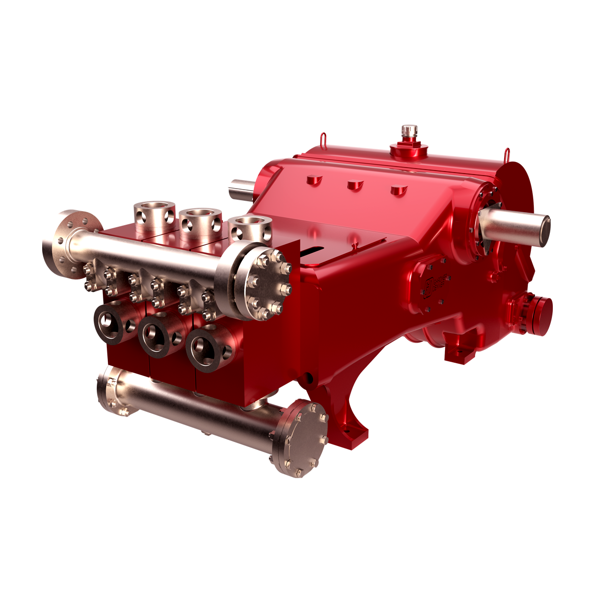
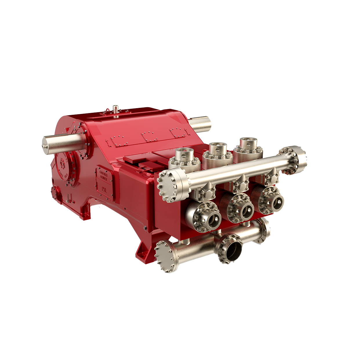
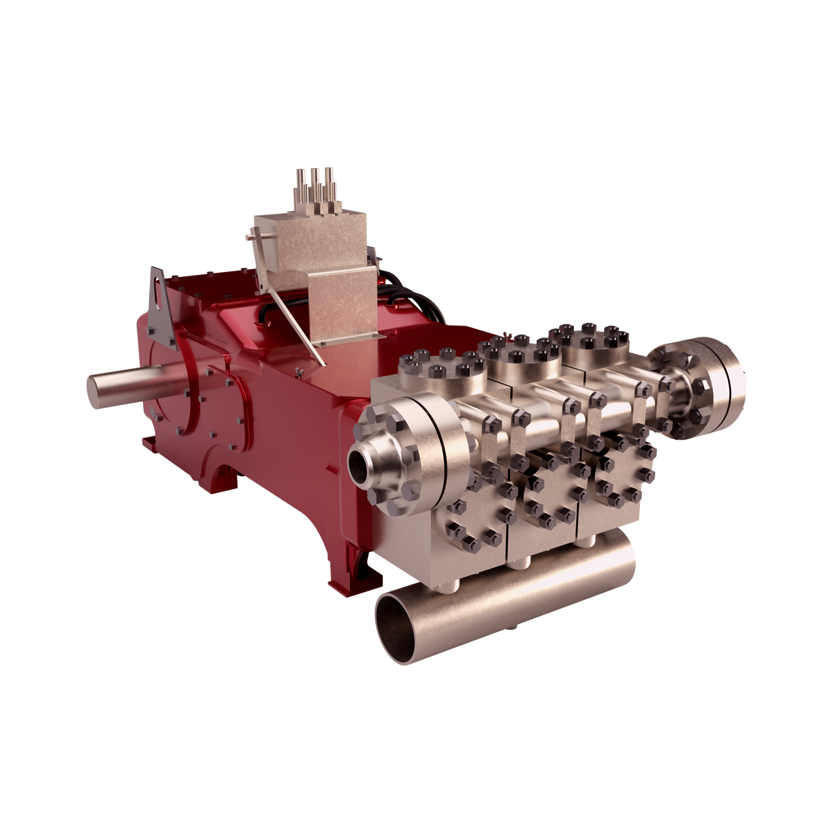
Pump Assembly, M1432HDD Mud Pump w/4 NPT X 2 NPT FLUID END, GOLD PISTON, AR VALVE ASSEMBLIES, SPLINED SHAFT, AUBURN #8, 5.5;1 GEAR BOX, LINER WASH SYSTEM


 8613371530291