
novatech mud pump pricelist
Weir provides the oil and gas industry with the best in full open valve and seat technology and manufactures a wide variety of valves and seats for workover pumps, high pressure well service fracturing pumps, cementing pumps and mud pumps through its Novatech™ pressure pumping equipment line.
Novatech leads the industry in full open valve and seat technology and manufactures valves and seats for workover pumps, high pressure well service fracturing pumps, cementing pumps and mud pumps. Novatech also manufactures caged assemblies for almost all well service pumps and applications, including workover, cementing, acidizing and fracking. Novatech developed the first valve and seat in the industry rated for continuous service at 7,500 psi. Products are 100% made in U.S.A.
Reasontek carry Weir/Novatech products for oilfield applications including valves, seats, inserts replacement of pump maintenance. Please check the catalogue below and let us know your request.

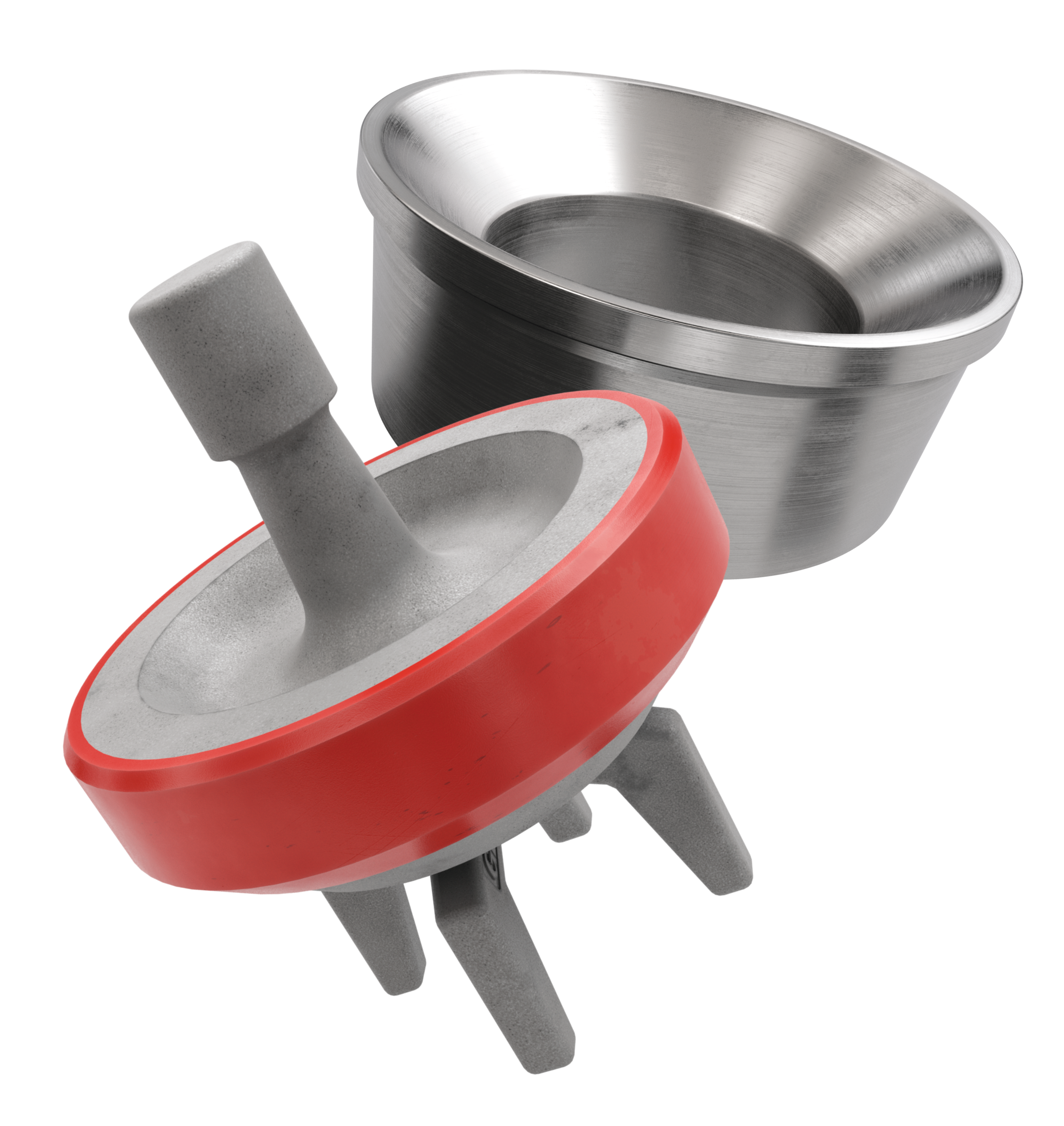
The frac pump valves and seats are also called valve and seat assembly. There are valve body, valve insert, valve seat, and O-ring, these four parts consist of the frac pump valves and seats, which are very critical vulnerable parts in fracturing pumps. In higher pressure frac pumps, the mating surface of the valve body and valve seat is generally a conical surface. Frac valves and seats are the no. 1 expendables cost. 8620H or 20CrMo can be used for forged frac valves and seats. Both the valve body and valve seat would be carburized or nitrided to enhance their impact resistance and wear resistance. Polyurethane is often used as the raw material for the valve insert. Compared with rubber, polyurethane has better strength and elasticity.
This FAQ lists some questions about frac pump valves and seats for you. These FAQs shall be able to answer some queries related to the well-service pump valves and seats.
Novatech is a valves and seats manufacturer in the US. Its first welding valves were supplied nationally in 1982. As one of the oldest and strongest frac valves and seat manufacturers, a wide variety of valves & seats manufactured by Novatech are used throughout the world.
Novatech’s four streamlined guide legs full open seat valve have greatly increased the reliability and performance. The web-type valve seat was achieved to maximize the metal-to-metal bearing area. However, the loads applied to the seat webs are not uniform, the flow is not limited because of the Novatech four streamlined guide legs and the metal-to-metal bearing area is regained, the Novatech full open valve seat assembly can keep the impact loads uniformly transmitted to the frac pump fluid end. One-piece valve bodies, the insert retention groove acts as a circular channel beam to add superior rigidity to the valve body.
TianyuMfg provides 100% interchangeable frac valves and seats with Novatech’s. Our valves and seats are manufactured by high-quality alloy steel and which is forged integrally. The developed high, medium, and low-end products suit different working conditions for you to choose, including work-over, acidizing, cementing, fracturing, and drilling.
The plungers size defines the frac pump fluid end size. The frac pump valves and seats change with the plunger size but not all the same, some fluid ends of different plunger specs also share the valves and seats of the same size. You can find the following charts which list the general sizes of frac pump valves and seats:
Tianyu Mfg. Provides various kinds of frac pump valves and seats. Contact TianyuMfg sales engineer to get the most appropriate valves and seats for your pumps.
The frac pump valve section is divided into the suction valve and discharge valve on the drawings. However, in order to make the disassemble and maintenance of the frac pump valve convenient, the suction and the discharge valve body adopt the exactly same design. The suction valve body is located at the lower part of the frac pump fluid end, and the discharge valve is located at the upper part of the frac pump fluid end.
By the reciprocating movement of the plunger, the suction valve and the discharge valve continuously open and close. When the suction valve keeps opening and the discharge valve closing, the liquid pours into the frac pump fluid end cylinder cavity through the suction manifold and the suction valve to complete the liquid suction. When the discharge valve keeps opening and the suction valve closing, the liquid discharge from the frac pump fluid end cylinder cavity through the discharge valve land the discharge pipe to complete the liquid discharge.
In the operation of the frac pump, the frac pump valves and seats are constantly opening and closing. Therefore, the closing speed of the frac pump valves and seats require special attention. There is a certain impact that emerges due to kinetic energy changing at the closing moment of the frac pump valves. The impact strength is related to the mass and closing speed of the frac pump valves and seats. The greater the mass and speed are, the greater the impact strength will be. The shock is the main factor that triggers the frac pump valves and seats to be damaged. It makes the allowable closing speed is a key parameter of the frac pump valves and seats design.
You need to prepare sufficient spare frac pump valves and seats parts. The quality of frac pump valves and seats directly affect the performance of the frac pump fluid end. Tianyu Mfg. serves low cost and superior performance frac pump valves and seats. As the valve body is manufactured as a one-piece, which increased resistance to abrasion and extrusion, also minimizes insert movement, leakage, and separation from the valve.
When the insert is almost damaged across the surface and caused the valve to leak, replace the insert. After replacing, no leakage keeps them working. Leakage till happened, replace the frac pump valve body. The leakage caused by the insert failure would arise the valve washout and fail easily tend to rapid erosion.
Increasing the metal-to-metal bearing area between the valve and seat is the only method to lengthen the life span of the frac pump valves and seats. The bigger this area, the bigger the area to absorb the high-impact energy from valve closing. We recommend the following tips for you as a reference.

The Weir Group PLC has agreed to acquire Novatech LLC, a US manufacturer of well service pump valves and valve seats for upstream oil and gas applications, for $176 million (£113 million) in cash.
Based in Dallas, Texas, Novatech, a family-owned business, produces a wide variety of proprietary valves and valve seats for high pressure applications such as frac, cement and mud pumps used in unconventional upstream oil and gas operations.
The business is well known to Weir, being a long standing local supplier to Weir SPM. Novatech achieved proforma revenues and EBITDA2 of US$61.6m and US$25.2m respectively3 for the most recent fiscal year ending 30 September 2011, with associated annual revenue growth of 88%. Positive trends continued in the final quarter of calendar 2011. Approximately 90% of revenues are generated from aftermarket demand.
The present invention generally relates to high-pressure pumps for pumping incompressible fluids. More particularly, the present invention relates to the fluid-handling sections, or fluid ends, of such high-pressure fluid pumps.
High-pressure, reciprocating, fluid pumps have been used for many years. Such pumps are employed to pressurize incompressible fluids to pressures upwards of 10,000 pounds per square inch (p.s.i.). A primary use of such pumps is in pumping drilling fluid, or mud, downhole during the drilling of oil wells. Such pumps also are used to provide pressurized fluid for applications such as water-blasting.
Because of the cyclic pressures (atmospheric to 10,000 p.s.i. and upward), and the frequently abrasive process fluid, the operating environment of such high-pressure pumps is very demanding. Therefore, much effort has been dedicated to designing a strong, durable, and easily maintained high-pressure, reciprocating, fluid pump. The high cyclical pressures encountered in such pumps makes pump components susceptible to fatigue failure. The presence of the process fluid, itself often corrosive, increases the susceptibility of pump components to fatigue failure through wet and corrosive fatigue. Many pump designs require crossbores, which intersect the pump cylinder, to deliver and carry away the process fluid. These intersecting crossbores create stress-concentrations, further rendering the pump susceptible to fatigue failure, and limiting the maximum pump pressure. Many known pumps require extremely high-strength materials to avoid the problem of fatigue failure. U.S. Pat. No. 3,260,217, Jul. 12, 1966, to Thresher, discloses a typical pump fluid end having intersecting crossbores.
Due to the abrasive nature of many of the process fluids (even tap water has a surprising amount of abrasive material suspended in it) abrasive wear of the valves and other components of the pump can be a significant problem. Most known pump designs use carefully machined and toleranced metal-to-metal suction and discharge valves. U.S. Pat. No. 5,037,276, Aug. 6, 1991, to Tremoulet, Jr., and U.S. Pat. No. 4,878,815, Nov. 5, 1989, to Stachowiak, are typical of such pumps having metal-to-metal valve assemblies. Such precision valves are expensive to manufacture and can be very difficult to replace in the field.
Because of high pump pressures, leakage from such pumps becomes a problem. Some known pumps use the pressure of the process fluid to hydrostatically bias the valve assembly in engagement with the cylinder. These pumps require extremely heavy discharge manifolds to contain the high pressure encountered. See U.S. Pat. No. 4,878,815, Nov. 7, 1989, to Stachowiak, for example. The weight and bulk of these discharge manifolds requires more than one person to remove the manifold for repair of the pump.
Cavitation, caused by gas entrapped in the pump fluid, can cause vibration and be very destructive to the pump. Therefore, such pumps must be designed to purge entrapped gas from the pressure chamber of the pump to minimize cavitation and the resulting destructive vibration.
It is, therefore, desirable to have a high-pressure, reciprocating, fluid pump that is strong, durable, easily and quickly repaired in the field, capable of pumping abrasive fluids, and easy and inexpensive to manufacture.
FIG. 1 is perspective view of a high-pressure, reciprocating, fluid pump including a fluid end according to the present invention; the power end of the pump is indicated in phantom lines.
With reference now to the figures, particularly FIG. 1, a typical, high-pressure, reciprocating fluid pump 11 is depicted. The pump comprises two portions, a power end 13, and a fluid end 15. The power end 13 is conventional and contains a crankshaft, connecting rods, and the various machinery required to reciprocate a plunger 17 within bore 19 of cylinder 21 of fluid end 15.
Major components of the fluid end 15 are cylinders 21, which may be individual cylinders or a single casting having several bores formed therein. Typical high-pressure, reciprocating fluid pumps have three or five cylinders 21. Such pumps are referred to as triplex or quintuplex pumps, respectively. Each cylinder 21 has a bore 19 therethrough, in which plunger 17 reciprocates to pressurize the process fluid. Cylinder 21 is covered at one end by manifold 57, which is affixed to power end 13 by means of threaded stay rods 59. Fluid end 15 also has a suction intake manifold 63 for delivery of the process fluid (not shown) to the pump cylinder 21. The process fluid is discharged from manifold discharge port 67 on discharge manifold 57.
Discharge fluid flow passages 37 are in fluid flow communication at one end thereof with pressure chamber PC, defined between plunger 17 and packing member 23, and valve body 33 and suction valve 27, and at an opposite end thereof with discharge valve receptacle 41. In a preferred embodiment of the present invention, at least one of the discharge fluid flow passages 37 is positioned at or near an uppermost point in pressure chamber PC. Positioning of discharge fluid flow passage 37 at or near an uppermost point of pressure chamber PC permits bubbles of entrapped gas in pressure chamber PC to float upward in the process fluid toward discharge fluid flow passage 37, thereby permitting rapid and efficient collection and discharge of entrapped bubbles from pressure chamber. This purging of entrapped gas prevents cavitation in the pump, which can result in extremely destructive vibration and component damage.
In a preferred embodiment of the present invention, another of discharge fluid flow passages 37 is positioned at or near a lowermost point in pressure chamber PC to permit collection and discharge of solid particles suspended in the process fluid. Discharge of solid material from pressure chamber PC prevents abrasive wear on pump components by those particles.
With reference to FIGS. 1 and 2, the operation of the pump fluid end according to the present invention will be discussed. Process fluid (not shown) enters fluid end 15 via suction manifold 63. Fluid is delivered from suction manifold 63 to valve body 33 by suction inlet 65 formed in cylinder 21. A rearward stroke of plunger 17 within cylinder 21 draws process fluid through suction fluid flow passages 35 in valve body 33, into suction valve receptacle 39, past suction valve 29 and suction valve seat 31, and into pressure chamber PC.
The improved fluid end for use in high-pressure, reciprocating, fluid pumps according to the present invention has a number of advantages. One advantage of the present invention is the simplicity of the design. The relatively small number of parts reduces manufacturing cost and assembly time, resulting in an inexpensive fluid end. The simplicity and small number of parts also renders the fluid end according to the present invention easy to maintain. Interference fits between the valve body and cylinder bore are eliminated, thereby rendering removal of the valve body a simple, one-person task.
Another advantage of the present invention is that conventional, readily available, abrasion-resistant valves are used in the design. This eliminates expensive precision machining of valves, and permits easy and inexpensive replacement of the valves, which are among the first pump components to wear out.
Yet another advantage of the present invention is that stress-inducing crossbores are not exposed to cyclical process fluid pressure, thereby minimizing the susceptibility of the pump to fatigue failure. This advantage permits the fluid end according the present invention to be manufactured from lower-strength and lower cost materials.
Still another advantage of the present invention is that cavitation, and resulting pump damage, is avoided by the positioning of the discharge fluid flow passages wherein entrapped gas is purged or discharged from the pressure chamber in a rapid and efficient manner.


 8613371530291