
oil rig mud pump diagram made in china

This website is using a security service to protect itself from online attacks. The action you just performed triggered the security solution. There are several actions that could trigger this block including submitting a certain word or phrase, a SQL command or malformed data.

This website is using a security service to protect itself from online attacks. The action you just performed triggered the security solution. There are several actions that could trigger this block including submitting a certain word or phrase, a SQL command or malformed data.

Emsco、Gardner-Denver, National oilwell, Ideco, Brewster, Drillmec, Wirth, Ellis, Williams, OPI, Mud King, LEWCO, Halliburton, SPM, Schlumberger, Weatherford

This website is using a security service to protect itself from online attacks. The action you just performed triggered the security solution. There are several actions that could trigger this block including submitting a certain word or phrase, a SQL command or malformed data.

The 2,200-hp mud pump for offshore applications is a single-acting reciprocating triplex mud pump designed for high fluid flow rates, even at low operating speeds, and with a long stroke design. These features reduce the number of load reversals in critical components and increase the life of fluid end parts.
The pump’s critical components are strategically placed to make maintenance and inspection far easier and safer. The two-piece, quick-release piston rod lets you remove the piston without disturbing the liner, minimizing downtime when you’re replacing fluid parts.
Mechanical pumps serve in a wide range of applications such as pumping water from wells, aquarium filtering, pond filtering and aeration, in the car industry for water-cooling and fuel injection, in the energy industry for pumping oil and natural gas or for operating cooling towers and other components of heating, ventilation and air conditioning systems. In the medical industry, pumps are used for biochemical processes in developing and manufacturing medicine, and as artificial replacements for body parts, in particular the artificial heart and penile prosthesis.
When a pump contains two or more pump mechanisms with fluid being directed to flow through them in series, it is called a multi-stage pump. Terms such as two-stage or double-stage may be used to specifically describe the number of stages. A pump that does not fit this description is simply a single-stage pump in contrast.
In biology, many different types of chemical and biomechanical pumps have evolved; biomimicry is sometimes used in developing new types of mechanical pumps.
Pumps can be classified by their method of displacement into positive-displacement pumps, impulse pumps, velocity pumps, gravity pumps, steam pumps and valveless pumps. There are three basic types of pumps: positive-displacement, centrifugal and axial-flow pumps. In centrifugal pumps the direction of flow of the fluid changes by ninety degrees as it flows over an impeller, while in axial flow pumps the direction of flow is unchanged.
Some positive-displacement pumps use an expanding cavity on the suction side and a decreasing cavity on the discharge side. Liquid flows into the pump as the cavity on the suction side expands and the liquid flows out of the discharge as the cavity collapses. The volume is constant through each cycle of operation.
Positive-displacement pumps, unlike centrifugal, can theoretically produce the same flow at a given speed (rpm) no matter what the discharge pressure. Thus, positive-displacement pumps are constant flow machines. However, a slight increase in internal leakage as the pressure increases prevents a truly constant flow rate.
A positive-displacement pump must not operate against a closed valve on the discharge side of the pump, because it has no shutoff head like centrifugal pumps. A positive-displacement pump operating against a closed discharge valve continues to produce flow and the pressure in the discharge line increases until the line bursts, the pump is severely damaged, or both.
A relief or safety valve on the discharge side of the positive-displacement pump is therefore necessary. The relief valve can be internal or external. The pump manufacturer normally has the option to supply internal relief or safety valves. The internal valve is usually used only as a safety precaution. An external relief valve in the discharge line, with a return line back to the suction line or supply tank provides increased safety.
Rotary-type positive displacement: internal or external gear pump, screw pump, lobe pump, shuttle block, flexible vane or sliding vane, circumferential piston, flexible impeller, helical twisted roots (e.g. the Wendelkolben pump) or liquid-ring pumps
Drawbacks: The nature of the pump requires very close clearances between the rotating pump and the outer edge, making it rotate at a slow, steady speed. If rotary pumps are operated at high speeds, the fluids cause erosion, which eventually causes enlarged clearances that liquid can pass through, which reduces efficiency.
Hollow disk pumps (also known as eccentric disc pumps or Hollow rotary disc pumps), similar to scroll compressors, these have a cylindrical rotor encased in a circular housing. As the rotor orbits and rotates to some degree, it traps fluid between the rotor and the casing, drawing the fluid through the pump. It is used for highly viscous fluids like petroleum-derived products, and it can also support high pressures of up to 290 psi.
Vibratory pumps or vibration pumps are similar to linear compressors, having the same operating principle. They work by using a spring-loaded piston with an electromagnet connected to AC current through a diode. The spring-loaded piston is the only moving part, and it is placed in the center of the electromagnet. During the positive cycle of the AC current, the diode allows energy to pass through the electromagnet, generating a magnetic field that moves the piston backwards, compressing the spring, and generating suction. During the negative cycle of the AC current, the diode blocks current flow to the electromagnet, letting the spring uncompress, moving the piston forward, and pumping the fluid and generating pressure, like a reciprocating pump. Due to its low cost, it is widely used in inexpensive espresso machines. However, vibratory pumps cannot be operated for more than one minute, as they generate large amounts of heat. Linear compressors do not have this problem, as they can be cooled by the working fluid (which is often a refrigerant).
Reciprocating pumps move the fluid using one or more oscillating pistons, plungers, or membranes (diaphragms), while valves restrict fluid motion to the desired direction. In order for suction to take place, the pump must first pull the plunger in an outward motion to decrease pressure in the chamber. Once the plunger pushes back, it will increase the chamber pressure and the inward pressure of the plunger will then open the discharge valve and release the fluid into the delivery pipe at constant flow rate and increased pressure.
Pumps in this category range from simplex, with one cylinder, to in some cases quad (four) cylinders, or more. Many reciprocating-type pumps are duplex (two) or triplex (three) cylinder. They can be either single-acting with suction during one direction of piston motion and discharge on the other, or double-acting with suction and discharge in both directions. The pumps can be powered manually, by air or steam, or by a belt driven by an engine. This type of pump was used extensively in the 19th century—in the early days of steam propulsion—as boiler feed water pumps. Now reciprocating pumps typically pump highly viscous fluids like concrete and heavy oils, and serve in special applications that demand low flow rates against high resistance. Reciprocating hand pumps were widely used to pump water from wells. Common bicycle pumps and foot pumps for inflation use reciprocating action.
These positive-displacement pumps have an expanding cavity on the suction side and a decreasing cavity on the discharge side. Liquid flows into the pumps as the cavity on the suction side expands and the liquid flows out of the discharge as the cavity collapses. The volume is constant given each cycle of operation and the pump"s volumetric efficiency can be achieved through routine maintenance and inspection of its valves.
This is the simplest form of rotary positive-displacement pumps. It consists of two meshed gears that rotate in a closely fitted casing. The tooth spaces trap fluid and force it around the outer periphery. The fluid does not travel back on the meshed part, because the teeth mesh closely in the center. Gear pumps see wide use in car engine oil pumps and in various hydraulic power packs.
A screw pump is a more complicated type of rotary pump that uses two or three screws with opposing thread — e.g., one screw turns clockwise and the other counterclockwise. The screws are mounted on parallel shafts that have gears that mesh so the shafts turn together and everything stays in place. The screws turn on the shafts and drive fluid through the pump. As with other forms of rotary pumps, the clearance between moving parts and the pump"s casing is minimal.
Widely used for pumping difficult materials, such as sewage sludge contaminated with large particles, a progressing cavity pump consists of a helical rotor, about ten times as long as its width. This can be visualized as a central core of diameter x with, typically, a curved spiral wound around of thickness half x, though in reality it is manufactured in a single casting. This shaft fits inside a heavy-duty rubber sleeve, of wall thickness also typically x. As the shaft rotates, the rotor gradually forces fluid up the rubber sleeve. Such pumps can develop very high pressure at low volumes.
Named after the Roots brothers who invented it, this lobe pump displaces the fluid trapped between two long helical rotors, each fitted into the other when perpendicular at 90°, rotating inside a triangular shaped sealing line configuration, both at the point of suction and at the point of discharge. This design produces a continuous flow with equal volume and no vortex. It can work at low pulsation rates, and offers gentle performance that some applications require.
A peristaltic pump is a type of positive-displacement pump. It contains fluid within a flexible tube fitted inside a circular pump casing (though linear peristaltic pumps have been made). A number of rollers, shoes, or wipers attached to a rotor compresses the flexible tube. As the rotor turns, the part of the tube under compression closes (or occludes), forcing the fluid through the tube. Additionally, when the tube opens to its natural state after the passing of the cam it draws (restitution) fluid into the pump. This process is called peristalsis and is used in many biological systems such as the gastrointestinal tract.
Efficiency and common problems: With only one cylinder in plunger pumps, the fluid flow varies between maximum flow when the plunger moves through the middle positions, and zero flow when the plunger is at the end positions. A lot of energy is wasted when the fluid is accelerated in the piping system. Vibration and
Triplex plunger pumps use three plungers, which reduces the pulsation of single reciprocating plunger pumps. Adding a pulsation dampener on the pump outlet can further smooth the pump ripple, or ripple graph of a pump transducer. The dynamic relationship of the high-pressure fluid and plunger generally requires high-quality plunger seals. Plunger pumps with a larger number of plungers have the benefit of increased flow, or smoother flow without a pulsation damper. The increase in moving parts and crankshaft load is one drawback.
Car washes often use these triplex-style plunger pumps (perhaps without pulsation dampers). In 1968, William Bruggeman reduced the size of the triplex pump and increased the lifespan so that car washes could use equipment with smaller footprints. Durable high-pressure seals, low-pressure seals and oil seals, hardened crankshafts, hardened connecting rods, thick ceramic plungers and heavier duty ball and roller bearings improve reliability in triplex pumps. Triplex pumps now are in a myriad of markets across the world.
Triplex pumps with shorter lifetimes are commonplace to the home user. A person who uses a home pressure washer for 10 hours a year may be satisfied with a pump that lasts 100 hours between rebuilds. Industrial-grade or continuous duty triplex pumps on the other end of the quality spectrum may run for as much as 2,080 hours a year.
The oil and gas drilling industry uses massive semi trailer-transported triplex pumps called mud pumps to pump drilling mud, which cools the drill bit and carries the cuttings back to the surface.
One modern application of positive-displacement pumps is compressed-air-powered double-diaphragm pumps. Run on compressed air, these pumps are intrinsically safe by design, although all manufacturers offer ATEX certified models to comply with industry regulation. These pumps are relatively inexpensive and can perform a wide variety of duties, from pumping water out of bunds to pumping hydrochloric acid from secure storage (dependent on how the pump is manufactured – elastomers / body construction). These double-diaphragm pumps can handle viscous fluids and abrasive materials with a gentle pumping process ideal for transporting shear-sensitive media.
Devised in China as chain pumps over 1000 years ago, these pumps can be made from very simple materials: A rope, a wheel and a pipe are sufficient to make a simple rope pump. Rope pump efficiency has been studied by grassroots organizations and the techniques for making and running them have been continuously improved.
Impulse pumps use pressure created by gas (usually air). In some impulse pumps the gas trapped in the liquid (usually water), is released and accumulated somewhere in the pump, creating a pressure that can push part of the liquid upwards.
Instead of a gas accumulation and releasing cycle, the pressure can be created by burning of hydrocarbons. Such combustion driven pumps directly transmit the impulse from a combustion event through the actuation membrane to the pump fluid. In order to allow this direct transmission, the pump needs to be almost entirely made of an elastomer (e.g. silicone rubber). Hence, the combustion causes the membrane to expand and thereby pumps the fluid out of the adjacent pumping chamber. The first combustion-driven soft pump was developed by ETH Zurich.
It takes in water at relatively low pressure and high flow-rate and outputs water at a higher hydraulic-head and lower flow-rate. The device uses the water hammer effect to develop pressure that lifts a portion of the input water that powers the pump to a point higher than where the water started.
The hydraulic ram is sometimes used in remote areas, where there is both a source of low-head hydropower, and a need for pumping water to a destination higher in elevation than the source. In this situation, the ram is often useful, since it requires no outside source of power other than the kinetic energy of flowing water.
Rotodynamic pumps (or dynamic pumps) are a type of velocity pump in which kinetic energy is added to the fluid by increasing the flow velocity. This increase in energy is converted to a gain in potential energy (pressure) when the velocity is reduced prior to or as the flow exits the pump into the discharge pipe. This conversion of kinetic energy to pressure is explained by the
A practical difference between dynamic and positive-displacement pumps is how they operate under closed valve conditions. Positive-displacement pumps physically displace fluid, so closing a valve downstream of a positive-displacement pump produces a continual pressure build up that can cause mechanical failure of pipeline or pump. Dynamic pumps differ in that they can be safely operated under closed valve conditions (for short periods of time).
Such a pump is also referred to as a centrifugal pump. The fluid enters along the axis or center, is accelerated by the impeller and exits at right angles to the shaft (radially); an example is the centrifugal fan, which is commonly used to implement a vacuum cleaner. Another type of radial-flow pump is a vortex pump. The liquid in them moves in tangential direction around the working wheel. The conversion from the mechanical energy of motor into the potential energy of flow comes by means of multiple whirls, which are excited by the impeller in the working channel of the pump. Generally, a radial-flow pump operates at higher pressures and lower flow rates than an axial- or a mixed-flow pump.
These are also referred to as All fluid pumps. The fluid is pushed outward or inward to move fluid axially. They operate at much lower pressures and higher flow rates than radial-flow (centrifugal) pumps. Axial-flow pumps cannot be run up to speed without special precaution. If at a low flow rate, the total head rise and high torque associated with this pipe would mean that the starting torque would have to become a function of acceleration for the whole mass of liquid in the pipe system. If there is a large amount of fluid in the system, accelerate the pump slowly.
Mixed-flow pumps function as a compromise between radial and axial-flow pumps. The fluid experiences both radial acceleration and lift and exits the impeller somewhere between 0 and 90 degrees from the axial direction. As a consequence mixed-flow pumps operate at higher pressures than axial-flow pumps while delivering higher discharges than radial-flow pumps. The exit angle of the flow dictates the pressure head-discharge characteristic in relation to radial and mixed-flow.
Regenerative turbine pump rotor and housing, 1⁄3 horsepower (0.25 kW). 85 millimetres (3.3 in) diameter impeller rotates counter-clockwise. Left: inlet, right: outlet. .4 millimetres (0.016 in) thick vanes on 4 millimetres (0.16 in) centers
Also known as drag, friction, peripheral, traction, turbulence, or vortex pumps, regenerative turbine pumps are class of rotodynamic pump that operates at high head pressures, typically 4–20 bars (4.1–20.4 kgf/cm2; 58–290 psi).
The pump has an impeller with a number of vanes or paddles which spins in a cavity. The suction port and pressure ports are located at the perimeter of the cavity and are isolated by a barrier called a stripper, which allows only the tip channel (fluid between the blades) to recirculate, and forces any fluid in the side channel (fluid in the cavity outside of the blades) through the pressure port. In a regenerative turbine pump, as fluid spirals repeatedly from a vane into the side channel and back to the next vane, kinetic energy is imparted to the periphery,
As regenerative turbine pumps cannot become vapor locked, they are commonly applied to volatile, hot, or cryogenic fluid transport. However, as tolerances are typically tight, they are vulnerable to solids or particles causing jamming or rapid wear. Efficiency is typically low, and pressure and power consumption typically decrease with flow. Additionally, pumping direction can be reversed by reversing direction of spin.
Steam pumps have been for a long time mainly of historical interest. They include any type of pump powered by a steam engine and also pistonless pumps such as Thomas Savery"s or the Pulsometer steam pump.
Recently there has been a resurgence of interest in low power solar steam pumps for use in smallholder irrigation in developing countries. Previously small steam engines have not been viable because of escalating inefficiencies as vapour engines decrease in size. However the use of modern engineering materials coupled with alternative engine configurations has meant that these types of system are now a cost-effective opportunity.
Valveless pumping assists in fluid transport in various biomedical and engineering systems. In a valveless pumping system, no valves (or physical occlusions) are present to regulate the flow direction. The fluid pumping efficiency of a valveless system, however, is not necessarily lower than that having valves. In fact, many fluid-dynamical systems in nature and engineering more or less rely upon valveless pumping to transport the working fluids therein. For instance, blood circulation in the cardiovascular system is maintained to some extent even when the heart"s valves fail. Meanwhile, the embryonic vertebrate heart begins pumping blood long before the development of discernible chambers and valves. Similar to blood circulation in one direction, bird respiratory systems pump air in one direction in rigid lungs, but without any physiological valve. In microfluidics, valveless impedance pumps have been fabricated, and are expected to be particularly suitable for handling sensitive biofluids. Ink jet printers operating on the piezoelectric transducer principle also use valveless pumping. The pump chamber is emptied through the printing jet due to reduced flow impedance in that direction and refilled by capillary action.
Examining pump repair records and mean time between failures (MTBF) is of great importance to responsible and conscientious pump users. In view of that fact, the preface to the 2006 Pump User"s Handbook alludes to "pump failure" statistics. For the sake of convenience, these failure statistics often are translated into MTBF (in this case, installed life before failure).
In early 2005, Gordon Buck, John Crane Inc.’s chief engineer for field operations in Baton Rouge, Louisiana, examined the repair records for a number of refinery and chemical plants to obtain meaningful reliability data for centrifugal pumps. A total of 15 operating plants having nearly 15,000 pumps were included in the survey. The smallest of these plants had about 100 pumps; several plants had over 2000. All facilities were located in the United States. In addition, considered as "new", others as "renewed" and still others as "established". Many of these plants—but not all—had an alliance arrangement with John Crane. In some cases, the alliance contract included having a John Crane Inc. technician or engineer on-site to coordinate various aspects of the program.
Not all plants are refineries, however, and different results occur elsewhere. In chemical plants, pumps have historically been "throw-away" items as chemical attack limits life. Things have improved in recent years, but the somewhat restricted space available in "old" DIN and ASME-standardized stuffing boxes places limits on the type of seal that fits. Unless the pump user upgrades the seal chamber, the pump only accommodates more compact and simple versions. Without this upgrading, lifetimes in chemical installations are generally around 50 to 60 percent of the refinery values.
Unscheduled maintenance is often one of the most significant costs of ownership, and failures of mechanical seals and bearings are among the major causes. Keep in mind the potential value of selecting pumps that cost more initially, but last much longer between repairs. The MTBF of a better pump may be one to four years longer than that of its non-upgraded counterpart. Consider that published average values of avoided pump failures range from US$2600 to US$12,000. This does not include lost opportunity costs. One pump fire occurs per 1000 failures. Having fewer pump failures means having fewer destructive pump fires.
As has been noted, a typical pump failure, based on actual year 2002 reports, costs US$5,000 on average. This includes costs for material, parts, labor and overhead. Extending a pump"s MTBF from 12 to 18 months would save US$1,667 per year — which might be greater than the cost to upgrade the centrifugal pump"s reliability.
Pumps are used throughout society for a variety of purposes. Early applications includes the use of the windmill or watermill to pump water. Today, the pump is used for irrigation, water supply, gasoline supply, air conditioning systems, refrigeration (usually called a compressor), chemical movement, sewage movement, flood control, marine services, etc.
Because of the wide variety of applications, pumps have a plethora of shapes and sizes: from very large to very small, from handling gas to handling liquid, from high pressure to low pressure, and from high volume to low volume.
Typically, a liquid pump can"t simply draw air. The feed line of the pump and the internal body surrounding the pumping mechanism must first be filled with the liquid that requires pumping: An operator must introduce liquid into the system to initiate the pumping. This is called priming the pump. Loss of prime is usually due to ingestion of air into the pump. The clearances and displacement ratios in pumps for liquids, whether thin or more viscous, usually cannot displace air due to its compressibility. This is the case with most velocity (rotodynamic) pumps — for example, centrifugal pumps. For such pumps, the position of the pump should always be lower than the suction point, if not the pump should be manually filled with liquid or a secondary pump should be used until all air is removed from the suction line and the pump casing.
Positive–displacement pumps, however, tend to have sufficiently tight sealing between the moving parts and the casing or housing of the pump that they can be described as self-priming. Such pumps can also serve as priming pumps, so-called when they are used to fulfill that need for other pumps in lieu of action taken by a human operator.
One sort of pump once common worldwide was a hand-powered water pump, or "pitcher pump". It was commonly installed over community water wells in the days before piped water supplies.
In parts of the British Isles, it was often called the parish pump. Though such community pumps are no longer common, people still used the expression parish pump to describe a place or forum where matters of local interest are discussed.
Because water from pitcher pumps is drawn directly from the soil, it is more prone to contamination. If such water is not filtered and purified, consumption of it might lead to gastrointestinal or other water-borne diseases. A notorious case is the 1854 Broad Street cholera outbreak. At the time it was not known how cholera was transmitted, but physician John Snow suspected contaminated water and had the handle of the public pump he suspected removed; the outbreak then subsided.
Modern hand-operated community pumps are considered the most sustainable low-cost option for safe water supply in resource-poor settings, often in rural areas in developing countries. A hand pump opens access to deeper groundwater that is often not polluted and also improves the safety of a well by protecting the water source from contaminated buckets. Pumps such as the Afridev pump are designed to be cheap to build and install, and easy to maintain with simple parts. However, scarcity of spare parts for these type of pumps in some regions of Africa has diminished their utility for these areas.
Multiphase pumping applications, also referred to as tri-phase, have grown due to increased oil drilling activity. In addition, the economics of multiphase production is attractive to upstream operations as it leads to simpler, smaller in-field installations, reduced equipment costs and improved production rates. In essence, the multiphase pump can accommodate all fluid stream properties with one piece of equipment, which has a smaller footprint. Often, two smaller multiphase pumps are installed in series rather than having just one massive pump.
A rotodynamic pump with one single shaft that requires two mechanical seals, this pump uses an open-type axial impeller. It is often called a Poseidon pump, and can be described as a cross between an axial compressor and a centrifugal pump.
The twin-screw pump is constructed of two inter-meshing screws that move the pumped fluid. Twin screw pumps are often used when pumping conditions contain high gas volume fractions and fluctuating inlet conditions. Four mechanical seals are required to seal the two shafts.
These pumps are basically multistage centrifugal pumps and are widely used in oil well applications as a method for artificial lift. These pumps are usually specified when the pumped fluid is mainly liquid.
A buffer tank is often installed upstream of the pump suction nozzle in case of a slug flow. The buffer tank breaks the energy of the liquid slug, smooths any fluctuations in the incoming flow and acts as a sand trap.
As the name indicates, multiphase pumps and their mechanical seals can encounter a large variation in service conditions such as changing process fluid composition, temperature variations, high and low operating pressures and exposure to abrasive/erosive media. The challenge is selecting the appropriate mechanical seal arrangement and support system to ensure maximized seal life and its overall effectiveness.
Pumps are commonly rated by horsepower, volumetric flow rate, outlet pressure in metres (or feet) of head, inlet suction in suction feet (or metres) of head.
From an initial design point of view, engineers often use a quantity termed the specific speed to identify the most suitable pump type for a particular combination of flow rate and head.
The power imparted into a fluid increases the energy of the fluid per unit volume. Thus the power relationship is between the conversion of the mechanical energy of the pump mechanism and the fluid elements within the pump. In general, this is governed by a series of simultaneous differential equations, known as the Navier–Stokes equations. However a more simple equation relating only the different energies in the fluid, known as Bernoulli"s equation can be used. Hence the power, P, required by the pump:
where Δp is the change in total pressure between the inlet and outlet (in Pa), and Q, the volume flow-rate of the fluid is given in m3/s. The total pressure may have gravitational, static pressure and kinetic energy components; i.e. energy is distributed between change in the fluid"s gravitational potential energy (going up or down hill), change in velocity, or change in static pressure. η is the pump efficiency, and may be given by the manufacturer"s information, such as in the form of a pump curve, and is typically derived from either fluid dynamics simulation (i.e. solutions to the Navier–Stokes for the particular pump geometry), or by testing. The efficiency of the pump depends upon the pump"s configuration and operating conditions (such as rotational speed, fluid density and viscosity etc.)
For a typical "pumping" configuration, the work is imparted on the fluid, and is thus positive. For the fluid imparting the work on the pump (i.e. a turbine), the work is negative. Power required to drive the pump is determined by dividing the output power by the pump efficiency. Furthermore, this definition encompasses pumps with no moving parts, such as a siphon.
Pump efficiency is defined as the ratio of the power imparted on the fluid by the pump in relation to the power supplied to drive the pump. Its value is not fixed for a given pump, efficiency is a function of the discharge and therefore also operating head. For centrifugal pumps, the efficiency tends to increase with flow rate up to a point midway through the operating range (peak efficiency or Best Efficiency Point (BEP) ) and then declines as flow rates rise further. Pump performance data such as this is usually supplied by the manufacturer before pump selection. Pump efficiencies tend to decline over time due to wear (e.g. increasing clearances as impellers reduce in size).
When a system includes a centrifugal pump, an important design issue is matching the head loss-flow characteristic with the pump so that it operates at or close to the point of its maximum efficiency.
Most large pumps have a minimum flow requirement below which the pump may be damaged by overheating, impeller wear, vibration, seal failure, drive shaft damage or poor performance.
The simplest minimum flow system is a pipe running from the pump discharge line back to the suction line. This line is fitted with an orifice plate sized to allow the pump minimum flow to pass.
A more sophisticated, but more costly, system (see diagram) comprises a flow measuring device (FE) in the pump discharge which provides a signal into a flow controller (FIC) which actuates a flow control valve (FCV) in the recycle line. If the measured flow exceeds the minimum flow then the FCV is closed. If the measured flow falls below the minimum flow the FCV opens to maintain the minimum flowrate.
As the fluids are recycled the kinetic energy of the pump increases the temperature of the fluid. For many pumps this added heat energy is dissipated through the pipework. However, for large industrial pumps, such as oil pipeline pumps, a recycle cooler is provided in the recycle line to cool the fluids to the normal suction temperature.oil refinery, oil terminal, or offshore installation.
Engineering Sciences Data Unit (2007). "Radial, mixed and axial flow pumps. Introduction" (PDF). Archived from the original (PDF) on 2014-03-08. Retrieved 2017-08-18.
Tanzania water Archived 2012-03-31 at the Wayback Machine blog – example of grassroots researcher telling about his study and work with the rope pump in Africa.
C.M. Schumacher, M. Loepfe, R. Fuhrer, R.N. Grass, and W.J. Stark, "3D printed lost-wax casted soft silicone monoblocks enable heart-inspired pumping by internal combustion," RSC Advances, Vol. 4, pp. 16039–16042, 2014.
"Radial, mixed and axial flow pumps" (PDF). Institution of Diploma Marine Engineers, Bangladesh. June 2003. Archived from the original (PDF) on 2014-03-08. Retrieved 2017-08-18.
Quail F, Scanlon T, Stickland M (2011-01-11). "Design optimisation of a regenerative pump using numerical and experimental techniques" (PDF). International Journal of Numerical Methods for Heat & Fluid Flow. 21: 95–111. doi:10.1108/09615531111095094. Retrieved 2021-07-21.
Rajmane, M. Satish; Kallurkar, S.P. (May 2015). "CFD Analysis of Domestic Centrifugal Pump for Performance Enhancement". International Research Journal of Engineering and Technology. 02 / #02. Retrieved 30 April 2021.
Wasser, Goodenberger, Jim and Bob (November 1993). "Extended Life, Zero Emissions Seal for Process Pumps". John Crane Technical Report. Routledge. TRP 28017.
Australian Pump Manufacturers" Association. Australian Pump Technical Handbook, 3rd edition. Canberra: Australian Pump Manufacturers" Association, 1987. ISBN 0-7316-7043-4.
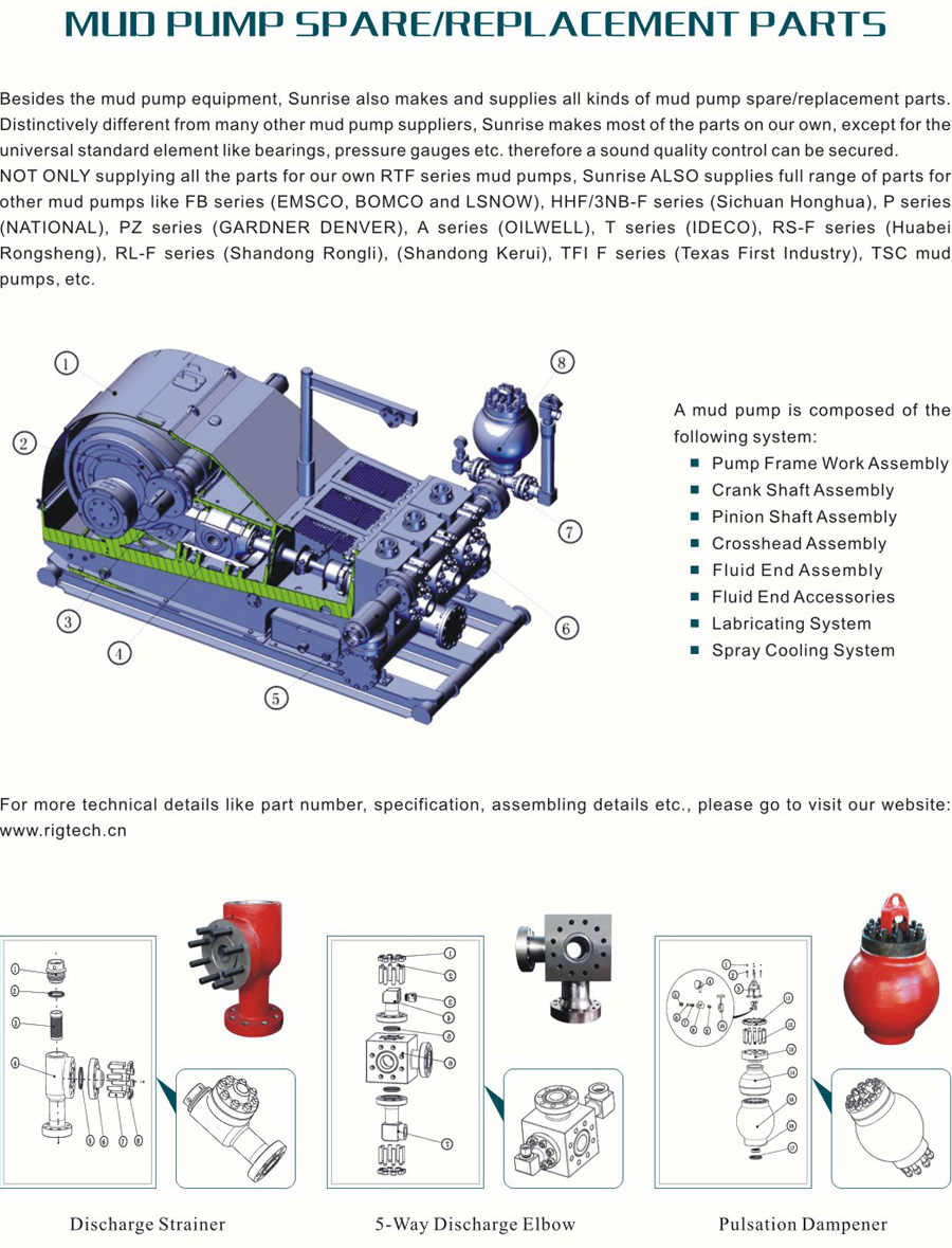
A Mud Pump may have many changeable parts, such as liner, piston, extension rod, pulsation dampener, valve, clamp, etc. Lake Petro could provide 100% interchangeable parts of many common brands of pump. We offer Liners with Ceramic (Zirconia and Aluminium oxide) and Steel (Metal and Bi-metal) materials. Piston assembly is the important spare parts and expendable parts of oil drilling mud pumps. Mud pump valve assy include valve body, valve seat, valve insert (valve rubber ). Pulsation Dampener is usually installed on the discharge line to reduce the fluctuation of pressure and displacement of the drilling mud pump. Fluid End Module is an important component of the hydraulic pump end of the mud pump.

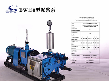
Triplex plunger-type mud pumps feature a reciprocating, positive displacement pump design utilizing three plungers to safely transfer high-viscosity fluids under high pressure over an extended depth. Although they have many industrial applications, these pumps have become an essential part of oil well drilling rigs where they’re used to provide smooth discharge of mud and debris from oil wells.
In addition to their use in drilling and well service operations, mud pumps are also frequently used to handle corrosive or abrasive fluids, as well as slurries containing relatively large particulates, in applications like commercial car washes, wastewater treatment, cementing, and desalination operations.
DAC Worldwide’s Representative Triplex, Plunger Mud Pump Dissectible (295-418) is an economical, conveniently-sized triplex plunger-type mud pump assembly that teaches learners hands-on maintenance activities commonly required on larger mud pump assemblies used in upstream oilfield production operations.
For example, mud pump assembly is used on well sites maintain downhole backpressure, to lubricate the rotating drill bit, and to help recycle and remove rock debris resulting from drilling activities. These heavy-duty, high-pressure pumps require regular refurbishment, inspection, and repair in the field.
DAC Worldwide’s dissectible mud pump assembly is a realistic sample that’s similar in geometry, design, and operating characteristics to the larger varieties learners will encounter on the job. DAC Worldwide chooses popular name-brand pumps for its dissectibles to ensure industrial and oil and gas training relevancy.
Using the dissectible mud pump, learners will gain hands-on experience with the operating principles, regular maintenance activities, and nomenclature/parts identification at a more convenient scale in the classroom or lab.
Technical training is most effective when learners can gain hands-on practice with industry-standard components they’ll encounter on the job. The Representative Triplex, Plunger Mud Pump Dissectible features a wide variety of common, industrial-quality components to provide learners with a realistic training experience that will build skills that translate easily to the workplace.
The Representative Triplex, Plunger Mud Pump Dissectible is a sturdy unit with a complete triplex, reciprocating, 20+ bhp plunger pump with .75" plunger, 1.5" stroke, and 3" cylinder sleeve. The unit allows for complete disassembly, assembly, and inspection, including removal of plungers, packing, and valves.
The dissectible mud pump comes with a formed-steel, powder-coated baseplate. It can also be mounted on a compatible DAC Worldwide Extended Electromechanical Workstation (903). Each unit comes with the manufacturer’s installation and maintenance manual.

Find W series mud pump from pressure grouting pump manufacturer - Saigao gruop in China. The W series mud pump can be widely used in all kinds of works in oil field, which is su...

The drilling industry has roots dating back to the Han Dynasty in China. Improvements in rig power and equipment design have allowed for many advances in the way crude oil and natural gas are extracted from the ground. Diesel/electric oil drilling rigs can now drill wells more than 4 miles in depth. Drilling fluid, also called drilling mud, is used to help transfer the dirt or drill cuttings from the action of the drilling bit back to the surface for disposal. Drill cuttings can vary in shape and size depending on the formation or design of the drill bit used in the process.
Watch the video below to see how the EDDY Pump outperforms traditional pumps when it comes to high solids and high viscosity materials commonly found on oil rigs.
Solids control equipment including shakers, hydro-cyclones, and centrifuges are utilized to clean the drill cuttings from the drilling fluid, which then allows it to be reused and recirculated. The circuit includes the mixing of the drilling fluid in the rig tanks.
The fluid is charged into high-pressure mud pumps which pump the drilling mud down the drill string and out through the bit nozzles cleaning the hole and lubricating the drill bit so the bit can cut efficiently through the formation. The bit is cooled by the fluid and moves up the space between the pipe and the hole which is called the annulus. The fluid imparts a thin, tough layer on the inside of the hole to protect against fluid loss which can cause differential sticking.
The fluid rises through the blowout preventers and down the flowline to the shale shakers. Shale shakers are equipped with fine screens that separate drill cutting particles as fine as 50-74 microns. Table salt is around 100 microns, so these are fine cuttings that are deposited into the half-round or cuttings catch tank. The drilling fluid is further cleaned with the hydro-cyclones and centrifuges and is pumped back to the mixing area of the mud tanks where the process repeats.
The drill cuttings contain a layer of drilling fluid on the surface of the cuttings. As the size of the drill cuttings gets smaller the surface area expands exponentially which can cause rheological property problems with the fluid. The fluid will dehydrate and may become too thick or viscous to pump so solids control and dilution are important to the entire drilling process.
One of the most expensive and troubling issues with drilling operations is the handling, processing, and circulation of drilling mud along with disposing of the unwanted drill cuttings. The drilling cuttings deposited in the half round tank and are typically removed with an excavator that must move the contents of the waste bin or roll-off box. The excavators are usually rented for this duty and the equipment charges can range from $200-300/day. Add in the cost for the day and night manpower and the real cost for a single excavator can be as much as $1800/day.
One solids control company reported the idle time for the excavator can be more than 8 hours for a 24-hour period with 8 hours of operation and 8 hours of shut down time. Fuel and time lost can cause an economic drag on rig operations. And lastly, there have been several accidents on each rig causing a potential for injury, loss of production, and lost revenue as the excavator must be repaired.
Offshore drilling rigs follow a similar process in which the mud is loaded into empty drums and held on the oil platform. When a certain number of filled drums is met, the drums are then loaded onto barges or vessels which take the drilling mud to the shore to unload and dispose of.
Oil field drilling operations produce a tremendous volume of drill cuttings that need both removal and management. In most cases, the site managers also need to separate the cuttings from the drilling fluids so they can reuse the fluids. Storing the cuttings provides a free source of stable fill material for finished wells, while other companies choose to send them off to specialty landfills. Regardless of the final destination or use for the cuttings, drilling and dredging operations must have the right high solids slurry pumps to move them for transport, storage, or on-site processing. Exploring the differences in the various drilling fluids, cutting complications, and processing options will reveal why the EDDY Pump is the best fit for the job.
The Eddy Pump is designed to move slurry with solid content as high as 70-80 % depending on the material. This is an ideal application for pumping drill cuttings. Drill cuttings from the primary shakers are typically 50% solids and 50% liquids. The Eddy Pump moves these fluids efficiently and because of the large volute chamber and the design of the geometric rotor, there is very little wear on the pump, ensuring long life and greatly reduced maintenance cost for the lifetime of the pump.
plumbed to sweep the bottom of the collection tank and the pump is recessed into a sump allowing for a relatively clean tank when the solids are removed. The Eddy Pump is sized to load a roll-off box in 10-12 minutes. The benefit is cuttings handling is quicker, easier, safer, and allows for pre-planning loading where the labor of the solids control technician is not monopolized by loading cuttings. Here, in the below image, we’re loading 4 waste roll-off bins which will allow the safe removal of cuttings without fear of the half-round catch tank running over.
Mud cleaning systems such as mud shaker pumps and bentonite slurry pumps move the material over screens and through dryers and centrifuges to retrieve even the finest bits of stone and silt. However, the pump operators must still get the raw slurry to the drill cuttings treatment area with a power main pump. Slurry pumps designed around the power of an Eddy current offer the best performance for transferring cuttings throughout a treatment system.
Options vary depending on whether the company plans to handle drill cuttings treatment on-site or transport the materials to a remote landfill or processing facility. If the plan is to deposit the cuttings in a landfill or a long-term storage container, it’s best to invest in a pump capable of depositing the material directly into transport vehicles. Most dredging operations rely on multiple expensive vacuum trucks, secondary pumps, and extra pieces of equipment.
Using an EDDY Pump will allow a project to eliminate the need for excavators/operators to load drill cuttings, substantially lowering both labor and heavy equipment costs. The EDDY Pump also allows a company to eliminate vacuum trucks once used for cleaning the mud system for displacing fluids. Since the pump transfers muds of all types at constant pressure and velocity throughout a system of practically any size, there’s little need for extra equipment for manual transfer or clean up on the dredge site.
The EDDY Pump can fill up a truck in only 10 minutes (compared to an hour) by using a mechanical means such as an excavator. For this reason, most companies can afford one piece of equipment that can replace half a dozen other units.
This application for the Eddy Pump has the potential to revolutionize the drilling industry. Moving the excavator out of the “back yard” (the area behind the rig from the living quarters) will make cuttings handling a breeze. Trucking can be easier scheduled during daylight hours saving on overtime and incidences of fatigued driving. Rig-site forklifts can move the roll-off boxes out of the staging area and into the pump loading area. The operator can save money on excavators rental, damages, and keep the technician operating the solids control equipment.
The EDDY Pump is ideal for drilling mud pump applications and can be connected directly onto the drilling rigs to pump the drilling mud at distances over a mile for disposal. This eliminates the need for costly vacuum trucks and also the manpower needed to mechanically move the drilling mud. The reasons why the EDDY Pump is capable of moving the drilling mud is due to the hydrodynamic principle that the pump creates, which is similar to the EDDY current of a tornado. This tornado motion allows for the higher viscosity and specific gravity pumping ability. This along with the large tolerance between the volute and the rotor allows for large objects like rock cuttings to pass through the pump without obstruction. The large tolerance of the EDDY Pump also enables the pump to last many times longer than centrifugal pumps without the need for extended downtime or replacement parts. The EDDY Pump is the lowest total life cycle pump on the market.

Triplex: This mud pump is used for drilling applications needing high pump pressure. This model works by decreasing the working fluid volume being discharged to generate pressure for producing the flow. There are three pistons in the triplex pump, with the middle piston generating more pressure on the crankshaft. High piston load can lead to excessive pressure and crankshaft failure if the components are not properly sourced.
Quintuplex:Quintuplex mud pump is perfect for pumping fluid at the time of drilling operations. It works as a continuous duty return piston. This is used in terms of its external bearings to provide crankshaft support to ensure the proper functioning of the sheaves.
Duplex: These mud pumps ensure that the mud circulation reaches the well"s bottom from the mud cleaning system. Duplex pumps have binocular floating seals as well as safety valves.
Saigao offers high-quality OEM mud pump spares, consumables, expendables and spare parts. Our mud pump parts are made with the highest standards of quality, offering competitive pricing and exceptional durability.

With the rise in offshore oil and gas, their exploration and development are moving toward deep-water (500–1500 m) and ultra-deep-water (>1500 m) areas, making deep-water–related technology a competitive field among countries (Brockway et al., 2019; Zhong, 2021). China is a newcomer in deep-water oil and gas exploration and lacks key technologies. Compared with onshore drilling, the environment of offshore oil drilling is more complex, and conventional drilling equipment and methods are difficult to adapt to unexpected situations (Gao et al., 2016).
Some field engineering cases show that as the water depth increases, the safe window between fracture-pressure and pore-pressure becomes narrow, and oil and gas development will face many technical difficulties, such as poor drilling conditions and high risks, which eventually lead to huge losses. Conventional drilling technology is costly and risky, and cannot meet the technical requirements of deep-water drilling. Dual-gradient drilling (DKD) can increase the drilling window through certain technical means, which can adapt to the harsh conditions of deep-water well and reduce the drilling risk. Since the 1990s, DKD has been developed and applied to tackle these challenges (Li et al., 2020).
This paper provides a series of outlooks to lead the exploration and development of deep-water oil and gas resources by reviewing the technology and equipment of dual-gradient drilling in deep water, detailing its principles, technical characteristics, and adaptability. Considering the characteristics and challenges, this paper divides dual-gradient drilling into two branches, riser drilling and riserless drilling (Xu et al., 2005).
While DGD can have two liquid column gradients in the wellbore annulus (Xu et al., 2005; Scanlon and Medeiros, 2012), the bottom hole pressure is equal to the sum of the fluid column pressure (seawater or a fluid with a density equal to that of seawater) from the sea level to the seafloor and the mud column from the seafloor to the bottom hole. The formula can be expressed as
After adopting DGD, the starting point of mud column pressure changes from the sea level to the mud on the seabed line theoretically, increasing the mud safety density window and improving the safety and reliability of underwater operating systems.
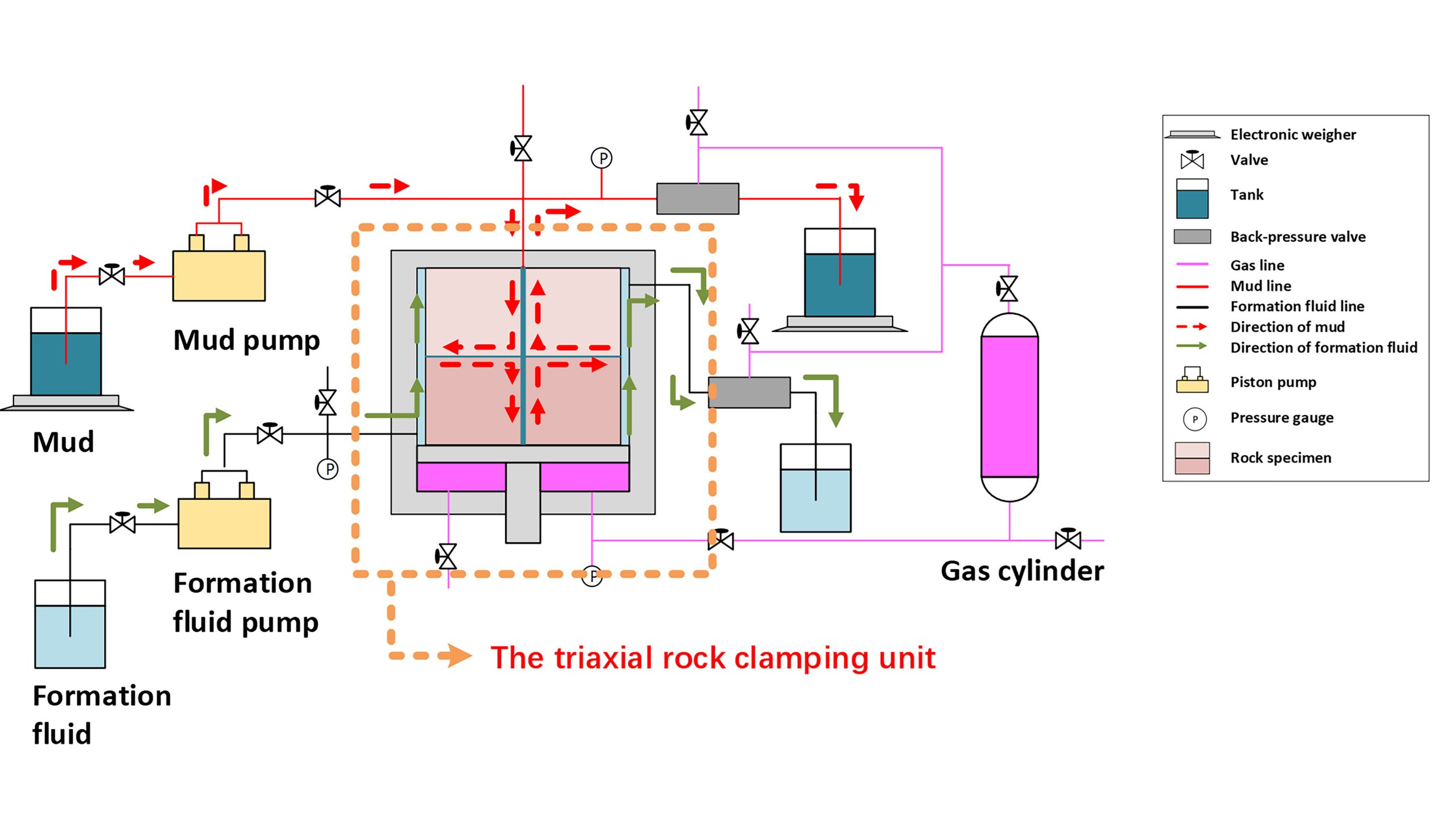
The present DGD techniques are shown in Figure 1; the implementation is mainly divided into riser drilling and riserless drilling. Riser drilling includes two categories: a subsea pumping system (SMD, Deep Vision) and a dual-density system (Hollow Microsphere, LSU riser gas-lift/dilution). Riser drilling is of two types: a jetting conductor setting and a riserless mud recovery system.
FIGURE 1. (A) Classification of DKD. (B) Schematic diagram of SMD. (C) Schematic diagram of the hollow microsphere system. (D) Schematic diagram of RMR.
At present, the main methods of realizing DKD with a riser in the industry include a subsea pumping system and a dual-density system (Wang et al., 2019; Pei et al., 2021).
The present subsea pumping system takes returns from the well annulus at the seafloor and pumps them back to the surface. By adjusting the inlet pressure of the seafloor pump to near seawater hydrostatic pressure, the idea of dual-gradient drilling is realized.
In 1996, SMD JIP developed a subsea mudlift drilling system; the principle is as follows: The rig’s mud pumps displace the mud down the drill string, through the bit, and back up the annulus to the seafloor. A subsea rotating diverter (similar to a rotating control device) diverts the mud flow from the annulus to a cutting processor, which crushes large cuttings into a size small enough to pass through the seafloor pump and up the return lines without clogging. After the mud and cuttings pass through the cutting processor, the seafloor pump displaces the returns up the return line and back to the rig.
The principle of dual-gradient drilling in the Deep Vision system is similar to the SMD. The difference is that the Deep Vision system adopts coiled tubing drilling technology, which ensures that when a drill tube is connected, the pump can be continuously circulated to ensure safe drilling when encountering a narrow density window and reduce the probability of sticking accidents.
The first annular injection method was based on the injection of hollow microspheres at the base of the riser. The hollow microspheres and drilling fluid are mixed in offshore pump sets to form a low-density fluid, which is pumped into the annulus from the seabed through pipelines to reduce the fluid density in the riser. The returning drilling fluid is separated by the ground-handling unit to separate the hollow microspheres and drill cuttings from the drilling fluid. These isolates enter the seawater pool, where the heavy drill cuttings sink to the bottom and the light hollow spheres float on the surface. The advantage of this system is that the hollow microspheres are incompressible and the linear pressure gradient generated can be better combined with the DKD ideas.
The second substance injected into the annular space is gas, which is similar to the previous system. In this system, the treated gas is compressed through the pipeline and injected at the base of the riser. The mud/gas separation equipment is used to separate the gas from the mud stream when circulated to the surface, realizing the secondary utilization of gas.
The technology can be divided into the following two categories: a jetting conductor setting and riserless mud recovery (Beck et al., 1991; Jonggeun, 1999; Jeanjean, 2002; Cohen et al., 2008).
In the 1960s, Mint-on proposed the jet casing technology, which has now become the preferred technology for deep-water and ultra-deep-water drilling worldwide. The combination of tubing and subsea drilling tools is placed in the water, and when the tubing reaches the subsea mud line, the subsea pump set is activated for drilling.
The riserless mud recovery (RMR) system is a new and emerging technology for open-hole drilling, which is applied for the open hole sections (no BOP installed), enabling return of fluid and cuttings in a closed system. As one of the essential pieces of equipment of a deep-water RMR system, the mud recovery line (MRL) is the only channel for subsea mud, which contains cuttings returning from the bottom hole to be transferred from the subsea to the rig for handling. The system is effectively a subsea pump, drawing mud returns from a suction module mounted on the wellhead via a hose line and pumping the fluid and cuttings back up to the rig.
1) The subsea pumping system, as one of the most prevalent and well-established methods for achieving dual-gradient drilling, can efficiently reduce the annular pressure of the riser; nevertheless, subsea pumps are expensive, and the reliability of complex subsea pumping systems is uncertain. In comparison, the dual-density system is more cost-effective. It does not necessitate a complex subsea pumping system, and it can provide a suitable pressure gradient with only a small amount of power. However, the primary problem of dual-density systems is the efficiency of the separator and the appropriate injection method. As a result, it is critical to continue developing a new type of high-efficiency downhole separator to realize the precise control of the wellbore pressure gradient.
This study was supported by the Open Foundation of Cooperative Innovation Center of Unconventional Oil and Gas, Yangtze University (Ministry of Education & Hubei Province), No. UOG 2022-03, and by the Open Fund of Hubei Key Laboratory of Drilling and Production Engineering for Oil and Gas (Yangtze University), No. YQZC202206.
Gao, D., Zhu, W., Li, J., Zhang, J., and Meng, Q. (2016). Scientific Problems and Technical Bottlenecks in Deepwater Oil &Gas Engineering ——Academic Review of the 147th Shuangqing Forum. China Basic Sci. 18 (03), 1–6.
Pei, Y., Liu, Q., Wang, C., and Wang, G. (2021). Energy-efficient Pressure Regulation Model and Experiment of Lift Pump System in Deepwater Dual-Gradient Drilling. J. Petroleum Sci. Eng. 203 (9), 108621. doi:10.1016/j.petrol.2021.108621
Xu, L., Jiang, S., Yin, Z., and Chen, G. (2005). Research on Principle of Dual-Gradient Drilling Technology. China Offshore Oil Gas 2005(04), 260–264.

Drilling consumables such as mud pump systems and their components can drastically increase your uptime while reducing costs and health/safety/environmental (HSE) risks. To support your drilling needs, Forum’s patented P-Quip® mud pump system offers a single-source solution that integrates high-quality fluid end components for maximum longevity and performance.
With more than 20 years of successful operation in severe environments, P-Quip offers a proven track record for the lowest cost of ownership in the industry. As part of our commitment to quality, our mud pump parts use patented Banded Bore™ technology that significantly reduces stress concentrations and leads to longer module life.

Mud hog pump is used to circulate oil drilling mud on a drilling rig at high pressure. Drilling fluid or oil drilling mud is circulated down through the drill string, to help cool, lubricate and clean the drill head, and back through the annulus at high pressures. The drilling mud is also used to suspend and carry out drill cuttings from the drill head as it is brought in and out of the hole.
We can provide more types of mud pumps than other oil well drilling equipment suppliers, and the classification methods are different. There are roughly the following types:
According to the number of times a piston reciprocates in a cylinder to inhale or discharge liquid once, it is divided into sing-acting pump and double-acting pump.
According to different driven method, it is divided into diesel mud pump and electric mud pump.It depends on fuel or energy which is available on around area of drilling rigs.
Brightway provides and designs complete solids control system for oil and gas drilling projects all over the world. With complete five phrase purification equipment, shale shaker, vacuum degasser, desander, desilter, decanting centrifuge, Brightway solids control system ensures good and efficient treatment effects of removing solids particles and gas bubbles in oil and gas drilling fluids. We design and make detail technical drawing of the system customized according to clients’ special requirements and drilling site application.
In Oil and Gas Drilling field, Brightway technical engineer supply the drilling fluids treatment solution and customized the drilling mud control system for customs" ZJ20/ZJ30/ZJ40/ZJ50/ZJ60/ZJ70 Drilling Rigs. if you have any questions, please send us the E-mail: brightway@brightwaysolids.comour technical engineers will reply to you as soon as possible!
1. Compact structure system for space limited area; trailer mounted mud system for flexible utilizing need; harmonious and functional mud tank layout for practical application.
3. And we adopts equipment parts in mud system with high level special characteristics such as water-proof, rust-proof, cold- resistant and heat-resisting for some area with special environment like moist area in Australia, cold area in Russia with subzero 50° temperature, and burning hot area in Middle east area, etc.


 8613371530291