
oil rig mud pump system free sample

Created specifically for drilling equipment inspectors and others in the oil and gas industry, the Oil Rig Mud Pump Inspection app allows you to easily document the status and safety of your oil rigs using just a mobile device. Quickly resolve any damage or needed maintenance with photos and GPS locations and sync to the cloud for easy access. The app is completely customizable to fit your inspection needs and works even without an internet signal.Try Template

The 2,200-hp mud pump for offshore applications is a single-acting reciprocating triplex mud pump designed for high fluid flow rates, even at low operating speeds, and with a long stroke design. These features reduce the number of load reversals in critical components and increase the life of fluid end parts.
The pump’s critical components are strategically placed to make maintenance and inspection far easier and safer. The two-piece, quick-release piston rod lets you remove the piston without disturbing the liner, minimizing downtime when you’re replacing fluid parts.

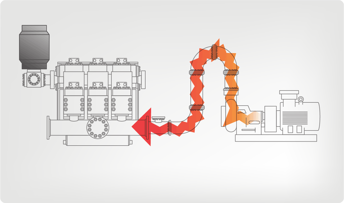
I’ve run into several instances of insufficient suction stabilization on rigs where a “standpipe” is installed off the suction manifold. The thought behind this design was to create a gas-over-fluid column for the reciprocating pump and eliminate cavitation.
When the standpipe is installed on the suction manifold’s deadhead side, there’s little opportunity to get fluid into all the cylinders to prevent cavitation. Also, the reciprocating pump and charge pump are not isolated.
The gas over fluid internal systems has limitations too. The standpipe loses compression due to gas being consumed by the drilling fluid. In the absence of gas, the standpipe becomes virtually defunct because gravity (14.7 psi) is the only force driving the cylinders’ fluid. Also, gas is rarely replenished or charged in the standpipe.
The suction stabilizer’s compressible feature is designed to absorb the negative energies and promote smooth fluid flow. As a result, pump isolation is achieved between the charge pump and the reciprocating pump.
The isolation eliminates pump chatter, and because the reciprocating pump’s negative energies never reach the charge pump, the pump’s expendable life is extended.
Investing in suction stabilizers will ensure your pumps operate consistently and efficiently. They can also prevent most challenges related to pressure surges or pulsations in the most difficult piping environments.
Sigma Drilling Technologies’ Charge Free Suction Stabilizer is recommended for installation. If rigs have gas-charged cartridges installed in the suction stabilizers on the rig, another suggested upgrade is the Charge Free Conversion Kits.

This website is using a security service to protect itself from online attacks. The action you just performed triggered the security solution. There are several actions that could trigger this block including submitting a certain word or phrase, a SQL command or malformed data.

Instead of using paper checklists when out in the field, drilling contractors and rig inspection services can generate a new inspection form from anywhere and the results are saved electronically.
Specifically designed for drilling companies and others in the oil and gas industry, the easy to use drilling rig inspections app makes it easy to log information about the drill rigs, including details about the drill rigs operators, miles logged and well numbers. The inspection form app covers everything from the mud pump areas and mud mixing area to the mud tanks and pits, making it easy to identify areas where preventative maintenance is needed. The drilling rig equipment checklist also covers health and safety issues, including the availability of PPE equipment, emergency response and preparedness processes, and other critical elements of the drilling process and drill press equipment.

If you run a mud rig, you have probably figured out that the mud pump is the heart of the rig. Without it, drilling stops. Keeping your pump in good shape is key to productivity. There are some tricks I have learned over the years to keeping a pump running well.
First, you need a baseline to know how well your pump is doing. When it’s freshly rebuilt, it will be at the top efficiency. An easy way to establish this efficiency is to pump through an orifice at a known rate with a known fluid. When I rig up, I hook my water truck to my pump and pump through my mixing hopper at idle. My hopper has a ½-inch nozzle in it, so at idle I see about 80 psi on the pump when it’s fresh. Since I’m pumping clear water at a known rate, I do this on every job.
As time goes on and I drill more hole, and the pump wears, I start seeing a decrease in my initial pressure — 75, then 70, then 65, etc. This tells me I better order parts. Funny thing is, I don’t usually notice it when drilling. After all, I am running it a lot faster, and it’s hard to tell the difference in a few gallons a minute until it really goes south. This method has saved me quite a bit on parts over the years. When the swabs wear they start to leak. This bypass pushes mud around the swab, against the liners, greatly accelerating wear. By changing the swab at the first sign of bypass, I am able to get at least three sets of swabs before I have to change liners. This saves money.
Before I figured this out, I would sometimes have to run swabs to complete failure. (I was just a hand then, so it wasn’t my rig.) When I tore the pump down to put in swabs, lo-and-behold, the liners were cut so badly that they had to be changed too. That is false economy. Clean mud helps too. A desander will pay for itself in pump parts quicker than you think, and make a better hole to boot. Pump rods and packing last longer if they are washed and lubricated. In the oilfield, we use a petroleum-based lube, but that it not a good idea in the water well business. I generally use water and dish soap. Sometimes it tends to foam too much, so I add a few tablets of an over the counter, anti-gas product, like Di-Gel or Gas-Ex, to cut the foaming.
Maintenance on the gear end of your pump is important, too. Maintenance is WAY cheaper than repair. The first, and most important, thing is clean oil. On a duplex pump, there is a packing gland called an oil-stop on the gear end of the rod. This is often overlooked because the pump pumps just as well with a bad oil-stop. But as soon as the fluid end packing starts leaking, it pumps mud and abrasive sand into the gear end. This is a recipe for disaster. Eventually, all gear ends start knocking. The driller should notice this, and start planning. A lot of times, a driller will change the oil and go to a higher viscosity oil, thinking this will help cushion the knock. Wrong. Most smaller duplex pumps are splash lubricated. Thicker oil does not splash as well, and actually starves the bearings of lubrication and accelerates wear. I use 85W90 in my pumps. A thicker 90W140 weight wears them out a lot quicker. You can improve the “climbing” ability of the oil with an additive, like Lucas, if you want. That seems to help.
Outside the pump, but still an important part of the system, is the pop-off, or pressure relief valve. When you plug the bit, or your brother-in-law closes the discharge valve on a running pump, something has to give. Without a good, tested pop-off, the part that fails will be hard to fix, expensive and probably hurt somebody. Pop-off valve are easily overlooked. If you pump cement through your rig pump, it should be a standard part of the cleanup procedure. Remove the shear pin and wash through the valve. In the old days, these valves were made to use a common nail as the shear pin, but now nails come in so many grades that they are no longer a reliable tool. Rated shear pins are available for this. In no case should you ever run an Allen wrench! They are hardened steel and will hurt somebody or destroy your pump.
One last thing that helps pump maintenance is a good pulsation dampener. It should be close to the pump discharge, properly sized and drained after every job. Bet you never thought of that one. If your pump discharge goes straight to the standpipe, when you finish the job your standpipe is still full of fluid. Eventually the pulsation dampener will water-log and become useless. This is hard on the gear end of the pump. Open a valve that drains it at the end of every job. It’ll make your pump run smoother and longer.

When choosing a size and type of mud pump for your drilling project, there are several factors to consider. These would include not only cost and size of pump that best fits your drilling rig, but also the diameter, depth and hole conditions you are drilling through. I know that this sounds like a lot to consider, but if you are set up the right way before the job starts, you will thank me later.
Recommended practice is to maintain a minimum of 100 to 150 feet per minute of uphole velocity for drill cuttings. Larger diameter wells for irrigation, agriculture or municipalities may violate this rule, because it may not be economically feasible to pump this much mud for the job. Uphole velocity is determined by the flow rate of the mud system, diameter of the borehole and the diameter of the drill pipe. There are many tools, including handbooks, rule of thumb, slide rule calculators and now apps on your handheld device, to calculate velocity. It is always good to remember the time it takes to get the cuttings off the bottom of the well. If you are drilling at 200 feet, then a 100-foot-per-minute velocity means that it would take two minutes to get the cuttings out of the hole. This is always a good reminder of what you are drilling through and how long ago it was that you drilled it. Ground conditions and rock formations are ever changing as you go deeper. Wouldn’t it be nice if they all remained the same?
Centrifugal-style mud pumps are very popular in our industry due to their size and weight, as well as flow rate capacity for an affordable price. There are many models and brands out there, and most of them are very good value. How does a centrifugal mud pump work? The rotation of the impeller accelerates the fluid into the volute or diffuser chamber. The added energy from the acceleration increases the velocity and pressure of the fluid. These pumps are known to be very inefficient. This means that it takes more energy to increase the flow and pressure of the fluid when compared to a piston-style pump. However, you have a significant advantage in flow rates from a centrifugal pump versus a piston pump. If you are drilling deeper wells with heavier cuttings, you will be forced at some point to use a piston-style mud pump. They have much higher efficiencies in transferring the input energy into flow and pressure, therefore resulting in much higher pressure capabilities.
Piston-style mud pumps utilize a piston or plunger that travels back and forth in a chamber known as a cylinder. These pumps are also called “positive displacement” pumps because they literally push the fluid forward. This fluid builds up pressure and forces a spring-loaded valve to open and allow the fluid to escape into the discharge piping of the pump and then down the borehole. Since the expansion process is much smaller (almost insignificant) compared to a centrifugal pump, there is much lower energy loss. Plunger-style pumps can develop upwards of 15,000 psi for well treatments and hydraulic fracturing. Centrifugal pumps, in comparison, usually operate below 300 psi. If you are comparing most drilling pumps, centrifugal pumps operate from 60 to 125 psi and piston pumps operate around 150 to 300 psi. There are many exceptions and special applications for drilling, but these numbers should cover 80 percent of all equipment operating out there.
The restriction of putting a piston-style mud pump onto drilling rigs has always been the physical size and weight to provide adequate flow and pressure to your drilling fluid. Because of this, the industry needed a new solution to this age-old issue.
As the senior design engineer for Ingersoll-Rand’s Deephole Drilling Business Unit, I had the distinct pleasure of working with him and incorporating his Centerline Mud Pump into our drilling rig platforms.
In the late ’90s — and perhaps even earlier — Ingersoll-Rand had tried several times to develop a hydraulic-driven mud pump that would last an acceptable life- and duty-cycle for a well drilling contractor. With all of our resources and design wisdom, we were unable to solve this problem. Not only did Miller provide a solution, thus saving the size and weight of a typical gear-driven mud pump, he also provided a new offering — a mono-cylinder mud pump. This double-acting piston pump provided as much mud flow and pressure as a standard 5 X 6 duplex pump with incredible size and weight savings.
The true innovation was providing the well driller a solution for their mud pump requirements that was the right size and weight to integrate into both existing and new drilling rigs. Regardless of drill rig manufacturer and hydraulic system design, Centerline has provided a mud pump integration on hundreds of customer’s drilling rigs. Both mono-cylinder and duplex-cylinder pumps can fit nicely on the deck, across the frame or even be configured for under-deck mounting. This would not be possible with conventional mud pump designs.
Centerline stuck with their original design through all of the typical trials and tribulations that come with a new product integration. Over the course of the first several years, Miller found out that even the best of the highest quality hydraulic cylinders, valves and seals were not truly what they were represented to be. He then set off on an endeavor to bring everything in-house and began manufacturing all of his own components, including hydraulic valves. This gave him complete control over the quality of components that go into the finished product.
The second generation design for the Centerline Mud Pump is expected later this year, and I believe it will be a true game changer for this industry. It also will open up the application to many other industries that require a heavier-duty cycle for a piston pump application.

Cavitation is an undesirable condition that reduces pump efficiency and leads to excessive wear and damage to pump components. Factors that can contribute to cavitation, such as fluid velocity and pressure, can sometimes be attributed to an inadequate mud system design and/or the diminishing performance of the mud pump’s feed system.
Although cavitation is avoidable, without proper inspection of the feed system, it can accelerate the wear of fluid end parts. Over time, cavitation can also lead to expensive maintenance issues and a potentially catastrophic failure.
When a mud pump has entered full cavitation, rig crews and field service technicians will see the equipment shaking and hear the pump “knocking,” which typically sounds like marbles and stones being thrown around inside the equipment. However, the process of cavitation starts long before audible signs reveal themselves – hence the name “the silent killer.”
Mild cavitation begins to occur when the mud pump is starved for fluid. While the pump itself may not be making noise, damage is still being done to the internal components of the fluid end. In the early stages, cavitation can damage a pump’s module, piston and valve assembly.
The imperceptible but intense shock waves generated by cavitation travel directly from the fluid end to the pump’s power end, causing premature vibrational damage to the crosshead slides. The vibrations are then passed onto the shaft, bull gear and into the main bearings.
If not corrected, the vibrations caused by cavitation will work their way directly to critical power end components, which will result in the premature failure of the mud pump. A busted mud pump means expensive downtime and repair costs.
Washouts are one of the leading causes of module failure and take place when the high-pressure fluid cuts through the module’s surface and damages a sealing surface. These unexpected failures are expensive and can lead to a minimum of eight hours of rig downtime for module replacement.
To stop cavitation before it starts, install and tune high-speed pressure sensors on the mud suction line set to sound an alarm if the pressure falls below 30 psi.
Accelerometers can also be used to detect slight changes in module performance and can be an effective early warning system for cavitation prevention.
Although the pump may not be knocking loudly when cavitation first presents, regular inspections by a properly trained field technician may be able to detect moderate vibrations and slight knocking sounds.
Gardner Denver offers Pump University, a mobile classroom that travels to facilities and/or drilling rigs and trains rig crews on best practices for pumping equipment maintenance.
Severe cavitation will drastically decrease module life and will eventually lead to catastrophic pump failure. Along with downtime and repair costs, the failure of the drilling pump can also cause damage to the suction and discharge piping.
When a mud pump has entered full cavitation, rig crews and field service technicians will see the equipment shaking and hear the pump ‘knocking’… However, the process of cavitation starts long before audible signs reveal themselves – hence the name ‘the silent killer.’In 2017, a leading North American drilling contractor was encountering chronic mud system issues on multiple rigs. The contractor engaged in more than 25 premature module washes in one year and suffered a major power-end failure.
Gardner Denver’s engineering team spent time on the contractor’s rigs, observing the pumps during operation and surveying the mud system’s design and configuration.
The engineering team discovered that the suction systems were undersized, feed lines were too small and there was no dampening on the suction side of the pump.
Following the implementation of these recommendations, the contractor saw significant performance improvements from the drilling pumps. Consumables life was extended significantly, and module washes were reduced by nearly 85%.
Although pump age does not affect its susceptibility to cavitation, the age of the rig can. An older rig’s mud systems may not be equipped for the way pumps are run today – at maximum horsepower.
It may be impractical to flush system piping during drilling operations. However, strainer screens should be checked daily to remove any debris or other flow restrictions.
Drilling mud is most commonly used in the process of drilling boreholes for a variety of reasons such as oil and gas extraction as well as core sampling. The mud plays an important role in the drilling process by serving numerous functions. The main function it is utilized for is as a lubricating agent. A large amount of friction is generated as drilling occurs which has the potential to damage the drill or the formation being drilled. The mud aids in the decrease in friction as well as lowering the heat of the drilling. It also acts a carrier for the drilled material so it becomes suspended in the mud and carried to the surface.
Using a Moyno progressive cavity pump, the drilling mud with suspended material can be pumped through a process to remove the solids and reuse the cleaned mud for further drilling.

Bentec completely redeveloped the concept of Mud Pumps. Being equipped with a direct-driven gearbox, an own developed motor, and a state-of-the-art pump housing, there is no need for an internal gear coming with many disadvantages and no more belt tensioning.
Bentec Mud Pumps are light weight and have a small footprint. The AC-powered motor is top or rear mounted – suitable for any drilling rig arrangement. The pump is available with 5 000 or 7 500 psi fluid ends, and all its parts that are subject to wear and tear meet API standards and are available worldwide.
A handling crane makes it easy to handle the fluid end components. Furthermore, Bentec uses a patented liner and valve clamping technology to reduce the maintenance time significantly. A quick-change liner and piston system serves for easy maintenance. A special feature of the Bentec MUD PUMP is the side-mounted gear drive.
This design eliminates the need for chain or belt tensioning systems. The two-stage helical gear feeds directly into a forged/welded crankshaft, which is balanced and provides quiet and vibration-reduced operation.
Liner cooling and gear oiler systems are included; a supercharge pump and a noise reduction package can be installed upon request. The Bentec MUD PUMP is the right choice especially when it comes to noise-sensitive environments such offshore or densely populated environments.
Beyond the supply of Mud Pumps, Bentec acts as system supplier. The pumps can be delivered together with a Bentec Power Control System and a Bentec Soft Pump System.

The invention relates generally to methods and procedures for maintaining well control during drilling operations. More specifically, the invention relates to methods and procedures where “riserless” drilling systems are used.
Deep water drilling techniques have, in the past, typically relied on the use of a large diameter marine riser to connect drilling equipment on a floating vessel or a drilling platform to a blowout preventer stack on a subsea wellhead disposed on the seafloor. The primary functions of the marine riser are to guide a drill string and other tools from the floating vessel to the subsea wellhead and to conduct drilling mud and earth cuttings from a subsea well back to the floating vessel. In deeper waters, conventional marine riser technology encounters severe difficulties. For example, if a deep water marine riser is filled with drilling mud, the drilling mud in the riser may account for a majority of the drilling mud in the circulation system. As water depth increases, the drilling mud volume increases. The large volume of drilling mud requires an excessively large circulation system and drilling vessel. Moreover, an extended length riser may experience high loads from ocean currents and waves. The energy from the currents and waves may be transmitted to the drilling vessel and may damage both the riser and the vessel.
In order to overcome problems associated with deep water drilling, a technique known as “riserless” drilling has been developed. Not all riserless techniques operate without a marine riser. The marine riser may still be used for the purpose of guiding the drill string to the wellbore and for protecting the drill string and other lines that run to and from the wellbore. When marine risers are used, however, they typically are filled with seawater rather than drilling mud. The seawater has a density that may be substantially less than that of the drilling mud, substantially reducing the hydrostatic pressure in the drilling system.
An example of a riserless drilling system is shown in U.S. Pat. No. 4,813,495 issued to Leach and assigned to the assignee of the present invention. A riserless drilling system 10 of the "495 patent is shown in FIG. 1 and comprises a drill string 12 including drill bit 20 and positive displacement mud motor 30. The drill string 12 is used to drill a wellbore 13. The system 10 also includes blowout preventer stack 40, upper stack package 60, mud return system 80, and drilling platform 90. As drilling is initiated, drilling mud is pumped down through the drill string 12 through drilling mud line 98 by a pump which forms a portion of mud processing unit 96. The drilling mud flow operates mud motor 30 and is forced through the bit 20. The drilling mud is forced up a wellbore annulus 13A and is then pumped to the surface through mud return system 80, mud return line 82, and subsea mudlift pump 81. This process differs from conventional drilling operations because the drilling mud is not forced upward to the surface through a marine riser annulus.
The blowout preventer stack 40 includes first and second pairs of ram preventers 42 and 44 and annular blowout preventer 46. The blowout preventers (“BOP”s) may be used to seal the wellbore 13 and prevent drilling mud from travelling up the annulus 13A. The ram preventers 42 and 44 include pairs of rams (not shown) that may seal around or shear the drill string 12 in order to seal the wellbore 13. The annular preventer 46 includes an annular elastomeric member that may be activated to sealingly engage the drill string 12 and seal the wellbore 13. The blowout preventer stack 40 also includes a choke/kill line 48 with an adjustable choke 50. The choke/kill line 48 provides a flow path for drilling mud and formation fluids to return to the drilling platform 90 when one or more of the BOPs (42, 44, and 46) have been closed.
The upper end of the BOP stack 40 may be connected to the upper stack package 60 as shown in FIG. 1. The upper stack package 60 may be a separate unit that is attached to the blowout preventer stack 40, or it may be the uppermost element of the blowout preventer stack 40. The upper stack package 60 includes a connecting point 62 to which mud return line 82 is connected. The upper stack package 60 may also include a rotating head 70. The rotating head 70 may be a subsea rotating diverter (“SRD”) that has an internal opening permitting passage of the drill string 12 through the SRD. The SRD forms a seal around the drill string 12 so that the drilling mud filled annulus 13A of the wellbore 13 is hydraulically separated from the seawater. The rotating head 70 typically includes both stationary elements that attach to the upper stack package 40 and rotating elements that sealingly engage and rotate with the drill string 12. There may be some slippage between rotating elements of the rotating head 70 and the drill string 12, but the hydraulic seal is maintained. During drill pipe “trips” to change the bit 20, the rotating head 70 is typically tripped into the hole on the drill string 12 before fixedly and sealingly engaging the upper stack package 60 that is connected to the BOP stack 40.
The mud return system 80 includes the subsea mudlift pump 81 that is positioned in the mud return line 82 adjacent to the upper stack package 60. The subsea mudlift pump 81 in the "495 patent is shown as a centrifugal pump that is powered by a seawater driven turbine 83 that is, in turn, driven by a seawater transmitting powerfluid line 84. The mud return system 80 boosts the flow of drilling mud from the seafloor 45 to the drilling mud processing unit 96 located on the drilling platform 90. Drilling mud is then cleaned of cuttings and debris and recirculated through the drill string 12 through drilling mud line 98.
When drilling a well, particularly an oil or gas well, there exists the danger of drilling into a formation that contains fluids at pressures that are greater than the hydrostatic fluid pressure in the wellbore. When this occurs, the higher pressure formation fluids flow into the well and increase the fluid volume and fluid pressure in the wellbore. The influx of formation fluids may displace the drilling mud and cause the drilling mud to flow up the wellbore toward the surface. The formation fluid influx and the flow of drilling and formation fluids toward the surface is known as a “kick.” If the kick is not subsequently controlled, the result may be a “blowout” in which the influx of formation fluids (which, for example, may be in the form of gas bubbles that expand near the surface because of the reduced hydrostatic pressure) blows the drill string out of the well or otherwise destroys a drilling apparatus. An important consideration in deep water drilling is controlling the influx of formation fluid from subsurface formations into the well to control kicks and prevent blowouts from occurring.
Drilling operations typically involve maintaining the hydrostatic pressure of the drilling mud column above the formation fluid pressure. This is typically done by selecting a specific drilling mud density and is typically referred to as “overbalanced” drilling. At the same time, however, the bottom hole pressure of the drilling mud column must be maintained below the formation fracture pressure. If the bottom hole pressure exceeds the formation fracture pressure, the formation may be damaged or destroyed and the well may collapse around the drill string.
A different type of drilling regime, known as “underbalanced” drilling, may be used to optimize the rate of penetration (“ROP”) and the efficiency of a drilling assembly. In underbalanced drilling, the hydrostatic pressure of the drilling mud column is typically maintained lower than the fluid pressure in the formation. Underbalanced drilling encourages the flow of formation fluids into the wellbore. As a result, underbalanced drilling operations must be closely monitored because formation fluids are more likely to enter the wellbore and induce a kick.
Once a kick is detected, the kick is typically controlled by “shutting in” the wellbore and “circulating out” the formation fluids that entered the wellbore. Referring again to FIG. 1, a well is typically shut in by closing one or more BOPs (42, 44, and/or 46). The fluid influx is then circulated out through the adjustable choke 50 and the choke/kill line 48. The choke 50 is adjustable and may control the fluid pressure in the well by allowing a buildup of back pressure (caused by pumping drilling mud from the mud processing unit 96) so that the kick may be circulated through the drilling mud processing unit 96 in a controlled process. The drilling mud processing unit 96 has elements that may remove any formation fluids, including both liquids and gases, from the drilling mud. The drilling mud processing unit 96 then recirculates the “cleaned” drilling mud back through the drill string 12. Typically, as the kick is circulated out, the drilling mud that is being pumped back into the wellbore 13 through drill string 12 has an increased density of a preselected value. The resulting increased hydrostatic pressure of the drilling mud column may equal or exceed the formation pressure at the site of the kick so that further kicks are prevented. This process is referred to as “killing the well.” The kick is circulated out of the wellbore and the drilling mud density is increased in substantially one complete circulation cycle (for example, by the time the last remnants of the drilling mud with the pre-kick mud density have been circulated out of the well, mud with the post-kick mud density has been circulated in as a substitute). When the wellbore is stabilized, drilling operations may be resumed or the drill string 12 may be tripped out of the wellbore 13. This method of controlling a kick is typically referred to as the “Wait and Weight” method. The Wait and Weight Method has historically been the preferred method of circulating out a kick because it generally exerts less pressure on the wellbore 13 and the formation and requires less circulating time to remove the influx from the drilling mud.
Another method for controlling a kick is typically referred to as the “Driller"s Method.” Generally, the Driller"s Method is accomplished in two steps. First, the kick is circulated out of the wellbore 13 while maintaining the drilling mud at an original mud weight. This process typically takes one complete circulation of the drilling mud in the wellbore 13. Second, drilling mud with a higher mud weight is then pumped into the wellbore 13 to overcome the higher formation pressure that produced the kick. Therefore, the Driller"s Method may be referred to as a “two circulation kill” because it typically requires at least two complete circulation cycles of the drilling mud in the wellbore 13 to complete the process.
A device known as a drill string valve (“DSV”) may be used as a component of either of the previously referenced well control methods. A DSV is typically located near a bottom hole assembly and includes a spring activated mechanism that is sensitive to the pressure inside the drill string. When drill string pressure is lowered below a preselected level, the spring activates a flow cone that moves to block flow ports in a flow tube. In order for drilling mud to flow through the drill string, the flow ports must be at least partially open. Thus, the DSV permits flow through the drill string if sufficient surface pump pressure is applied to the drilling fluid column, and the DSV typically only permits flow in one direction so that it act as a check valve against mud flowing back toward the surface.
The spring pressure in the DSV may be adjusted to account for factors such as the depth of the wellbore, the hydrostatic pressure exerted by the drilling mud column, the hydrostatic pressure exerted by the seawater from a drilling mud line to the surface, and the diameter of drill pipe in the drill string. The drilling mud line may be defined as a location in a well where a transition from seawater to drilling mud occurs. For example, in the system 10 shown in FIG. 1, the drilling mud line is defined by the hydraulic seal of the rotating head 70 that separates the drilling mud of the wellbore annulus 13A from seawater. The DSV may be used to stop drilling mud from experiencing “free-fall” when the mud circulation pumps are shut down and the well is shut-in.
Using the system of the Leach "495 patent as an example, when the pumps of the mud processing unit 96 are shut down and no DSV is present in the drill string 12, the mud column hydrostatic pressure in the drill string 12 is greater than the sum of the hydrostatic pressure of the drilling mud in the wellbore annulus 13A and a suction pressure generated by the subsea mudlift pump 81. Drilling mud, therefore, free-falls in the drill string into the wellbore annulus 13A until the hydrostatic pressure of the mud column in the drill string 12 is equalized with the sum of the hydrostatic pressure of the drilling mud in the wellbore annulus 13A and the mudlift pump 81 suction pressure. Thus, the well continues to flow while equilibrium is established. The continued flow of drilling mud in the well after pump shut-down may typically be referred to as an “unbalanced U-tube” effect. The DSV, which should be in a closed position after the pumps are shut-down, may prevent the free-fall of drilling mud in the wellbore that may be attributable to the unbalanced U-tube.
In contrast, in conventional drilling systems where drilling mud is returned to the surface through the wellbore annulus, the drilling mud circulation system forms a “balanced U-tube” because there is no flow of drilling mud in the well after the surface pumps are shut down. The well does not flow because the hydrostatic pressure of the drilling mud in the drill string is balanced with the hydrostatic pressure of the mud in the wellbore annulus.
Well control procedures may be complicated by a leaking DSV. For example, the spring in the DSV must be adjusted correctly so that it will activate the flow cone and block the flow ports when pressure is removed from the mud column such as by shutting down the surface mud pumps. If the flow ports remain at least partially open, the well will continue to flow after all the pumps have been shut down and/or after the well has been fully shut-in. Further, the DSV may develop leaks from flow erosion, corrosion, or other factors.
Typically, there are two conditions where the DSV may be checked for leaks. The first condition is during normal drilling operations when, for example, circulation of drilling mud is stopped so that a drill pipe connection may be made (all pumps must be shut off for the DSV check). In this case, an effort is made to distinguish between a leaking DSV and a possible kick. The second condition occurs after the well has been fully shut-in on a kick (again, all pumps must be shut off for the DSV check). In this case, an effort is made to distinguish between a leaking DSV and additional flow that may have entered the well from the known kick. In both cases it is important to check the DSV for leaks because otherwise it may be difficult to determine if additional flow in the well is due to a leaking or partially open DSV or to additional flow that has entered the well from a kick.
Reliable methods are needed to quickly and efficiently control and eliminate kicks that are experienced when drilling wells. The methods must account for the special configurations of deepwater drilling systems and must function both with and without the use of a DSV. The methods must also be designed to determine the difference between a leaking DSV and a kick that may have occurred during drilling operations, and also between a leaking DSV and additional flow that may occur after a kick is shut-in. In either case, the kicks come from formations with pore pressures that exceed the fluid pressure in the wellbore. Finally, the methods should result in a hydrostatically “dead” well so that the drill string may be removed from the wellbore or so that drilling operations may resume.
One aspect of the invention is a method for controlling a subsea well including shutting at least one blowout preventer, opening at least one isolation line, and circulating a formation fluid influx out of a well while an inlet pressure of a subsea mudlift pump is adjusted to maintain a substantially constant drill pipe pressure at an initial circulating pressure. Kill weight drilling mud is pumped from the surface into the well, and the drill pipe pressure is reduced according to a preselected drill pipe pressure decline schedule until the kill weight drilling mud reaches a bottom of the well. After the kill weight drilling mud reaches the bottom of the well, the drill pipe pressure is maintained at a final circulating pressure by adjusting the inlet pressure of the subsea mudlift pump. Kill weight drilling mud is then circulated from the bottom of the well to the surface at the final circulation pressure.
In another aspect, the invention is a method for controlling a subsea well including shutting at least one blowout preventer, opening at least one isolation line, and circulating a formation fluid influx out of a well while an inlet pressure of a subsea mudlift pump is adjusted to maintain a substantially constant drill pipe pressure at an initial circulating pressure. Kill weight drilling mud is pumped from the surface into the well, and the inlet pressure of the subsea mudlift pump is held substantially constant until the kill weight drilling mud reaches a bottom of the well. The inlet pressure of the subsea mudlift pump is then adjusted to maintain the drill pipe pressure at a final circulating pressure. Kill weight drilling mud is then circulated from the bottom of the well to the surface at the final circulating pressure.
In an embodiment of the invention, a full shut-in of the well is carried out after a dynamic shut-in procedure, such as the procedure disclosed in co-pending U.S. application Ser. No. 09/731,295, titled “Method For Dynamic Shut-In of a Subsea Mudlift Drilling System,” filed on even date herewith, assigned to the assignee of the present invention, and incorporated by reference herein.
FIG. 2 shows an example of a typical drilling system 101 used in an embodiment of the invention. The drilling system 101 presented in the example is provided for illustration of the methods used in the present invention and is not intended to limit the scope of the invention. The methods of the invention may function in arrangements that differ from the drilling system 101 shown in FIG. 2.
The drilling system 101 has a surface drilling mud circulation system 100 that includes a drilling mud storage tank (not shown separately) and surface mud pumps (not shown separately). The surface drilling mud circulation system 100 and other surface components of the drilling system 101 are located on a drilling platform (not shown) or a floating drilling vessel (not shown). The surface drilling mud circulation system 100 pumps drilling mud through a surface pipe 102 into a drill string 104. The drill string 104 may include drill pipe (not shown), drill collars (not shown), a bottom hole assembly (not shown), and a drill bit 106 and extends from the surface to the bottom of a well 108. The drill string 104 may also include a drill string valve 110.
The drilling system 101 may include a marine riser 112 that extends from the surface to a subsea wellhead assembly 114. The marine riser 112 forms an annular chamber 120 that is typically filled with seawater. A lower end of the marine riser 112 may be connected to a subsea accumulator chamber (“SAC”) 116. The SAC 116 may be connected to a subsea rotating diverter (SRD) 118. The SRD 118 functions to rotatably and sealingly engage the drill string 104 and separates drilling mud in a wellbore annulus 122 from seawater in an annular chamber 120 of the marine riser 112.
A discharge port of the SRD 118 may be connected to an inlet of a subsea mudlift pump (“MLP”) 124. An outlet of the MLP 124 is connected to a mud return line 126 that returns drilling mud from the wellbore annulus 122 to the surface drilling mud circulation system 100. The MLP 124 typically operates in an automatic rate control mode so that an inlet pressure of the MLP 124 is maintained at a constant level. Typically, the MLP 124 inlet pressure is maintained at a level equal to the seawater hydrostatic pressure at the depth of the MLP 124 inlet plus a differential pressure that may be, for example, 50 psi. However, the MLP 124 pumping rate may be adjusted so that back pressure may be generated in the wellbore annulus 122. The MLP 124 may be a centrifugal pump, a triplex pump, or any other type of pump known in the art that may function to pump drilling mud from the seafloor 128 to the surface. Moreover, the MLP 124 may be powered by any means known in the art. For example, the MLP 124 may be powered by a seawater powered turbine or by seawater pumped under pressure from an auxiliary pump.
The BOP stack 130 also includes isolation lines such as lines 146, 148, 150, 152, and 154 that permit drilling mud to be circulated through choke/kill lines 156 and 158 after any of the BOPs have been closed. The isolation lines (146, 148, 150, 152, and 154) and choke/kill lines (156 and 158) may be selectively opened or closed. The isolation lines (146, 148, 150, 152, and 154) and the choke/kill lines (156 and 158) are important to the function of the invention because drilling mud must be able to flow in a controlled manner from the surface, through the well, and back after the BOPs are closed.
When drilling a wellbore 168, kicks may be encountered when formation fluid pressure is greater than a hydrostatic pressure in the wellbore 168. When a kick is detected, the aforementioned dynamic shut-in process is initiated and completed so that a kick intensity may be determined. The kick intensity may be defined as, for example, a volume of formation fluid that enters the wellbore 168 or as an excess of formation fluid (or “pore”) pressure above a fluid pressure in the wellbore 168. However, the determination of the kick intensity may be complicated by the presence of a DSV 110 in the drill string 104. For example, a spring in the DSV 110 must be adjusted correctly so that it will activate the flow cone and block the flow ports when pump pressure is removed from the mud column in the drill string 104 such as by stopping the pumps. If the flow ports remain at least partially open, the well will continue to flow after the pumps have been shut down and the well 108 has been fully shut-in. The DSV 110 may develop leaks from flow erosion or corrosion, among other causes. Therefore, it may be difficult to determine if flow in the well experienced after the pumps are shut down and the well is fully shut-in is due to a leaking or partially open DSV 110, or is due to additional influx that has entered the well 108. Continued flow may also make it difficult or impossible to calculate the volume of the kick or the drilling mud density required to effectively counteract the elevated formation pressure. Therefore, knowledge of whether the DSV 110 is leaking is important to well control procedures taken after the well 108 is fully shut-in. A method for detecting a leak in a DSV 110 is disclosed in co-pending U.S. application Ser. No. 09/730,891, titled “Method for Detecting a Leak in a Drill String Valve,” filed on even date herewith, assigned to the assignee of the present invention, and incorporated by reference herein.
While circulating and drilling, a hydrostatic pressure exerted by the drilling mud in the annulus 122, in addition to an annular friction pressure (“AFP”) generated by the surface pump and an inlet pressure maintained by the MLP 124, contribute to a bottom hole pressure (“BHP”) that opposes formation pore pressures encountered near a bottom of the well 108. The AFP is a pressure loss experienced (when the surface pumps are running) because of the friction between the drilling mud and annular surfaces (outer walls of the drill string 104 and inner walls of the well 108). Different drilling environments involve both overbalanced and underbalanced drilling operations, but kicks in both situations result from formation pore pressures that are higher than the BHP exerted by the fluid column. As previously, described, the MLP 124 inlet pressure is maintained at a level substantially equal to the seawater hydrostatic pressure (“SWH”) at the depth of the MLP 124 inlet plus a selected differential pressure that may be, for example, a nominal amount such as 50 psi. Simultaneously, the MLP 124 maintains an outlet pressure sufficient to pump drilling mud from the seafloor 128 to the surface. A drill pipe pressure (“DPP”) is maintained by the surface drilling mud pumps to circulate drilling mud through the drill string 104, through the drill bit 106, and into the wellbore annulus 122. The MLP 124 inlet pressure may be electronically monitored from the surface through a gauge (not shown) located in or near the inlet of the subsea MLP 124.
The SIDP is then used to calculate a kill mud weight (“KMW”). The KMW may be defined as a drilling mud density required to at least balance an elevated formation pore pressure that induced the kick in the well 108.
Note that the SIDP is also a full underbalance pressure (“FUP”) as well as the kick intensity based on pressure. Each is defined as an excess of formation fluid (pore) pressure over the BHP that existed prior to the kick with the surface pumps shut off, the U-tube balanced (or the DSV 110 holding), and the MLP 124 inlet pressure at the normal SWH plus the nominal differential pressure. Under those conditions, the BHP would be the sum of the MLP 124 inlet pressure and the hydrostatic pressure of the original mud in the annulus 122.
After the well 108 has been dynamically shut-in (as shown in block 200 of FIG. 4), a full shut-in of the well (108 in FIG. 2) is begun by stopping the surface mud pumps. Full well shut-in is shown as block 210 in FIG. 4. When the surface pumps are shut-down, the fluid level begins to fall in the drill pipe because of the unbalanced U-tube. In order to prevent further flow, the MLP (124 in FIG. 2) inlet pressure may be increased by an amount at least equal to the AFP. Because the MLP (124 in FIG. 2) is still running, the U-tube will flow in a controlled manner. After the U-tube reaches equilibrium, the MLP (124 in FIG. 2) may be shut down and the MLP (124 in FIG. 2) inlet pressure may be measured. If the measured shut-in MLP (124 in FIG. 2) inlet pressure is greater than the MLP (124 in FIG. 2) inlet pressure held during the U-tube procedure, then either the well (108 in FIG. 2) flowed during the U-tube procedure or the AFP was underestimated. If the well (108 in FIG. 2) did not flow during the U-tube and the shut-in MLP (124 in FIG. 2) inlet pressure is higher than that held during the U-tube, a more accurate estimate of the AFP may be determined from the increase in the MLP (124 in FIG. 2) inlet pressure. Before beginning to “circulate out” the kick, an alternate method of estimating the FUP (on which to base the KMW) may be performed.
“ΔM/W” may be defined as a hydrostatic pressure differential that is produced by a difference in densities of mud and seawater from the surface to the “mud line.” The mud line may be defined as the point at which the SRD (118 in FIG. 2) separates drilling mud in the wellbore annulus (122 in FIG. 2) from seawater in the annulus (120 in FIG. 2) of the marine riser (112 in FIG. 2). In effect, the hydrostatic pressure in the wellbore is reduced by the amount of the ΔM/W because the pressure at the MLP (124 in FIG. 2) inlet is maintained essentially at the seawater hydrostatic pressure (SWH). “Gm” is a gradient of the drilling mud, “Gw” is a gradient of the seawater, “WD” is a water depth, and “FL” is a fluid level in the drill pipe. The gradients reflect magnitudes of pressure changes in a fluid column with respect to depth. For example, the seawater gradient (Gw) differs from the drilling mud gradient (Gm) because a density of the drilling mud may be greater than a density of the seawater. Therefore, as depth is increased, a column of more dense drilling mud may exhibit a greater hydrostatic pressure than an equivalent vertical depth column of seawater. The gradients reflect these fluid properties as a pressure change per foot of fluid level.
Surface mud system storage tanks are also known as “pits.” If a fluid influx has entered a well (108 in FIG. 2), a mud volume in the pits, measured after the dynamic shut-in procedure, may be greater than the volume contained in the pits while circulating prior to the kick. The increase in mud volume is the “pit gain.” After the U-tube has reached equilibrium and the well (108 in FIG. 2) has been fully shut-in, actual (measured) and theoretical (based upon a geometry of the drill string (104 in FIG. 2)) U-tube mud pit volume increases may be compared to detect and measure any additional flow that occurred during the U-tube to arrive at a final total pit gain.
Measurement of the pit gain and an analysis of the annular geometry of the well (108 in FIG. 2) may enable a calculation of the kick, or influx, gradient (“Gi”). Determination of Gi is important because the type of fluid entering the well as the kick influx fluid can be postulated from it. For example, gas produces higher wellbore pressures while oil may be more difficult to dispose of at the surface. Gi may be calculated as:
After the SIDP (also called the FUP) has been determined during the dynamic shut-in procedure and confirmed during the full shut-in procedure, and after the KMW has been calculated, procedures should be initiated for circulating the kick out of the well (108 in FIG. 2) without waiting for influx gradient/kick volume calculations to be made. The recommended method for circulating the kick out of the well is the Driller"s Method, as shown in block 230 of FIG. 4. The Driller"s Method is preferred in Subsea Mudlift Drilling (“SMD”) for several reasons:
Due to greater water and drilling depths, plus mud line pressure control, there may be relatively little gas expansion and pressure increase while the kick is in the wellbore below the MLP.
“OMW” is an original drilling mud weight (a pre-kick mud weight), “TD” is a total depth of the well (108 in FIG. 2) below the drilling platform or vessel (typically measured below a “rig floor”), and, as defined above, “WD” is the water depth. Next, an initial circulating pressure (“ICP”) for circulating the kick out of the well (108 in FIG. 2) may be calculated as:
If the actual KMW is increased above the KMW calculated in the previous equation to include a “trip margin,” any overbalance pressure may appear in the BHP as the drill pipe is filled with KMW drilling mud (refer to Stage 4 below) or while the wellbore annulus (122 in FIG. 2) is being displaced (refer to Optional Stage 4 below). The trip margin may be included to help reduce any “swabbing” effect produced by the removal of the drill string (104 in FIG. 2) from the well (108 in FIG. 2), but should generally be deferred until the influx is out of the well (108 in FIG. 2). Swabbing refers to the pressure reduction that may occur in the wellbore (168 in FIG. 2) when drilling mud is “pulled” toward the surface as the drill string (104 in FIG. 2) is removed from the well (108 in FIG. 2). Swabbing of the well may decrease BHP and may result in a kick.
After the KMW and the ICP have been calculated, the MLP (124 in FIG. 2) inlet pressure is set at the stabilized shut-in pressure determined at the completion of the full shut-in procedure. At this setting, the MLP (124 in FIG. 2) inlet pressure consists of the seawater hydrostatic pressure (SWH), plus the full underbalance pressure (FUP) and an initial hydrostatic loss due to the influx. The surface mud pumps are then activated and set to a preselected kick circulating rate (“KCR”). The KCR may be an original drilling pump rate that was used prior to the influx or another preselected value. As the surface pumps are set to the KCR, the MLP (124 in FIG. 2) inlet pressure is held constant at the shut-in level. Thus, after pump start-up the BHP is composed of a sum of a formation fluid (pore) pressure and the annular friction pressure (AFP), which corresponds to the chosen KCR. If the KCR is substantially equal to the pre-kick drilling pump rate, the AFP may remain substantially constant.
As the surface pumps reach the KCR, the MLP (124 in FIG. 2) inlet pressure may be reduced in a controlled procedure. As a first option, the MLP (124 in FIG. 2) inlet pressure may be reduced by an amount substantially equal to the AFP when the surface pumps are started in order to hold the BHP substantially equal to the formation pore pressure. A second option is to hold the MLP (124 in FIG. 2) rate constant until a preselected back pressure is imposed on the BHP. The back pressure may help prevent flow caused by gas expansion in the well (108 in FIG. 2). After a preselected back pressure is generated, the MLP (124 in FIG. 2) inlet pressure may then be reduced by an amount substantially equal to the AFP. The following discussions assume that neither of these two options to reduce the MLP (124 in FIG. 2) inlet pressure was adopted.
The surface pumps will begin to fill the drill pipe at a constant pump rate (typically the KCR). The drill pipe will have to be completely filled (to account for the drop in the FL experienced because of the flow of the unbalanced U-tube) before a drill pipe pressure (DPP) measurement may be recorded. When the DPP may be measured and stabilizes at the calculated ICP, the MLP (124 in FIG. 2) may be switched to manual control and a MLP (124 in FIG. 2) pump rate may be adjusted to maintain the DPP at a substantially constant pressure (typically the ICP) until the kick has been circulated out of the well (108 in FIG. 2) and clean OMW drilling mud is returning to the surface.
If the DPP does not stabilize at the calculated ICP, circulation should continue and the stabilized DPP may serve as a new ICP. This step should be taken because if the drill string (104 in FIG. 2) has become partially plugged during shut-down and restart, pumping at the originally calculated ICP may cause a drop in the BHP and may permit the well to flow in an uncontrolled manner. The MLP (124 in FIG. 2) may be adjusted through manual control procedures to assist in maintaining the new ICP as the surface pump rate is maintained at the KCR.
While the kick is being circulated out of the well, at least one surface mud tank (not shown) in the surface mud circulation system (100 in FIG. 2) should be isolated and a mud density in the isolated tank should be increased to the KMW. If the surface mud circulation system (100 in FIG. 2) is not configured so that drilling mud may be changed to the KMW while circulating, another full shut-in procedure may be completed (after the influx has been circulated out) and the system restarted when the KMW drilling mud is ready for circulation. After the kick has been completely circulated out of the well (108 in FIG. 2), the MLP (124 in FIG. 2) inlet pressure may be recorded and a final circulating pressure (“FCP”) should be calculated as:
“DPPpre-kick” is the pre-kick drill pipe pressure and “ΔM/WOMW” is the hydrostatic pressure differential calculated with the OMW gradient, Gm. “ΔM/WKMW” is a new hydrostatic pressure differential calculated with a kill mud weight gradient, Gk, that is characteristic of the KMW. AFP is the annular friction pressure.
As the influx is pumped up the annulus (122 in FIG. 2) in the first circulation, the MLP (124 in FIG. 2) inlet pressure will rise due to gas expansion and consequent additional loss of hydrostatic pressure until the influx reaches the MLP (124 in FIG. 2). As the influx passes through the MLP (124 in FIG. 2) and out of the well (108 in FIG. 2), the MLP (124 in FIG. 2) inlet pressure falls to the sum of the SWH and the FUP. At a constant pump kick circulating rate (KCR) and initial circulating pressure (ICP), the MLP (124 in FIG. 2) inlet pressure will remain substantially constant at this level until the mud weight is changed. The first circulation is complete when clean OMW drilling mud reaches the surface.
Drilling mud at the KMW may be circulated to the bit (106 in FIG. 2) in a second circulation of the Driller"s Method, as shown in block 240 of FIG. 4. For example, drilling mud at the KMW may be circulated to the bit (106 in FIG. 2) following a drill pipe pressure decline schedule. Drill pipe pressure decline schedules are known in the art and may be calculated using well parameters such as well depth, well geometry, and the KMW. Drill pipe pressure decline schedules typically maintain the BHP at a preselected level above the formation pore pressure while the drill pipe is filled with KMW drilling mud. The preselected level may be generally equal to the AFP of the subsea system. However, the preselected level may be a different value and is not intended to limit the scope of the invention.
Because kill circulation may occur at relatively high pump rates, friction pressure drops in the subsea mudlift drilling (SMD) system (101 in FIG. 2) may be substantially different than friction pressure drops in conventional drilling systems. For example, in conventional kick circulation the assumption that the drill string friction pressure drop is distributed linearly along the entire length of a drill string, including the bottom hole assembly and the bit, does not cause substantial error. In SMD system (101 in FIG. 2), the friction pressure drops in individual components of the drill string (104 in FIG. 2) may be much larger, causing greater errors due to non-linearity. Therefore, conventional linear drill pipe pressure reduction schedules may have to be modified for use in SMD wells.
After the KMW drilling mud reaches the bit (106 in FIG. 2), the DPP should be held constant at the final circulating pressure (FCP) with a substantially constant surface pump rate (the KCR) until the KMW drilling mud reaches the surface. The DPP may be held at the FCP by adjusting the MLP (124 in FIG. 2) inlet pressure while the surface pump rate is held substantially constant at the KCR. The pressures in the well (108 in FIG. 2) may remain substantially constant after the KMW drilling mud reaches the MLP (124 in FIG. 2) inlet. Moreover, as the wellbore annulus (122 in FIG. 2) is filled with KMW drilling mud, the MLP (124 in FIG. 2) inlet pressure will gradually fall to a level equal to the SWH that exists external to the MLP (124 in FIG. 2). The MLP (124 in FIG. 2) inlet pressure decrease, which may be substantially equal to the full underbalance pressure (FUP), will indicate that the FUP that has been maintained by the MLP (124 in FIG. 2) suction pressure has been replaced by a corresponding increase in the drilling mud hydrostatic pressure. However, the MLP (124 in FIG. 2) inlet pressure must still be maintained at least at the SWH in order to maintain MLP (124 in FIG. 2) operating integrity.
Also note that as the well (108 in FIG. 2) is filled with kill mud weight (KMW) drilling mud, the AFP may increase because of the increased mud density. Calculation of the increase in the AFP may become important if the mud density is high so that the increase in AFP is correspondingly large. For example, a relatively accurate knowledge of the AFP is helpful to explain MLP (124 in FIG. 2) inlet pressure behavior as the KMW drilling mud moves up the annulus (122 in FIG. 2) and nears the seafloor (128 in FIG. 2). The net effect of higher AFP developing as the KMW drilling mud is being pumped up the annulus (122 in FIG. 2) is that the MLP (124 in FIG. 2) inlet pressure must be lowered more rapidly to keep the DPP from increasing. Then, before the KMW drilling mud reaches the MLP (124 in FIG. 2), the MLP (124 in FIG. 2) inlet pressure will be lowered to a minimum level (which is substantially equal to the seawater hydrostatic pressure (SWI) plus a differential pressure that may be, for example, 50 psi), and thereafter the drill pipe pressure (DPP) will rise at the substantially constant KCR until the kill mud reaches the MLP (124 in FIG. 2), after which the DPP will remain substantially constant.
An alternate procedure (for block 240 of FIG. 4) may be followed when circulating the KMW drilling mud through the drill pipe and back to the surface. After the kick is completely circulated out of the well (108 in FIG. 2) in Stage 3, KMW drilling mud may be circulated to the bit (106 in FIG. 2) while holding the MLP (124 in FIG. 2) inlet pressure substantially constant at a level established at the end of the first circulation (Stage 3). Recall that at this level, the MLP (124 in FIG. 2) inlet pressure is substantially equal to the SWH plus the FUP. When the KMW drilli


 8613371530291