
parts list for atm mud pump pricelist

We stock fluid end parts for the5×6 mud pump, 5×6-1/4 FM45 mud pump, 5×8 mud pump, 5-1/2×8 mud pump, 5X10 mud pump, 4-1/2×5 mud pump, 7-1/2×8 mud pump, and 7-1/2X10 mud pump. The Gardner Denver mud pump model numbers for the above pumps are as follows: 5X6-FGFXG, 5X8-FDFXX, 5-1/2X8-FDFXX, 5X10-FDFXD, 4-1/2X5-FFFXF, 7-1/2X8-FYFXX, 7-1/2X10-FYFXD. We also handle Wheatley, Gaso, Worthington, Failing and Centerline parts and pumps. We also stock Foot Valve, Liner Puller, Valve Seat Puller, (4″ Inline Check Valve. Our Gardner Denver mud pump parts are not only competitively priced, they are also made in the USA. Oil Recommended by Gardner Denver. Call any of our experienced representatives to get the help and knowledge you deserve.

This website is using a security service to protect itself from online attacks. The action you just performed triggered the security solution. There are several actions that could trigger this block including submitting a certain word or phrase, a SQL command or malformed data.

The 2,200-hp mud pump for offshore applications is a single-acting reciprocating triplex mud pump designed for high fluid flow rates, even at low operating speeds, and with a long stroke design. These features reduce the number of load reversals in critical components and increase the life of fluid end parts.
The pump’s critical components are strategically placed to make maintenance and inspection far easier and safer. The two-piece, quick-release piston rod lets you remove the piston without disturbing the liner, minimizing downtime when you’re replacing fluid parts.

The BEP, or Best Efficiency Point, is the point at which the pump operates at peak efficiency. At the BEP, flow enters and leaves the pump with a minimum amount of flow separation, turbulence, and other losses. The closer a pump operates to its BEP, the less wear the pump will experience, which increases the reliability of the pump. In the below image, the BEP is located at the apex of the pump efficiency curve (green line). If a vertical line is drawn from the BEP down to the pump curve (black line), the head and flow rate at the BEP can be determined by looking at where this line is in relation to horizontal and vertical axes.
A closely related topic to the BEP is the Preferred Operating Region, or POR. The POR is a range of rates of flow to either side of predicted BEP within which the hydraulic efficiency and the operational reliability of the pump are not substantially degraded. Within this region, the design service life of the pump will not be affected by the internal hydraulic loads or flow- induced vibration. Operating a pump within the POR ensures higher reliability and lower energy consumption. A typical range for the POR is shown on in Figure 1. Note that the POR is defined in ANSI/HI 9.6.3 Rotodyanamic Pumps Guideline for Operating Regions, and the POR changes depending if the pump radial (centrifugal), mixed or axial flow type.
A wider range of flows, outside the POR, over which the service life of a pump is acceptable, is designed the Allowable operating region (AOR). The limits to AOR are determined by requirements other than energy consumption and should defined with the help of the pump manufacturer. Some factors that determine the AOR are:
There are a multitude of negative consequences that arise when a pump is operated significantly above or below its BEP that can result in accelerated pump wear and premature failures. For example operating at excessively low flow rates could cause higher radial loading on the impeller causing excessive shaft deflection leading to premature seal failures. At excessively high flow rates the pump’s required suction head may not be met and the pump could cavitate.
For more information on pump operation see HI’s eLearning certificate course on pump systems assessments and ANSI/HI 9.6.3 Rotodynamic Pumps Guideline for Operating Regions at www.pumps.org.
Two categories of single mechanical seals are (1) inside-mounted and (2) outside-mounted. The primary difference between the two styles is that inside mounted seals are contained within the equipment seal chamber and outside-mounted seals are mounted external of the equipment housing. See Figures 2 and 3 for diagrams of an inside-mounted and outside-mounted single seal.
Refer to HI Guidebook Mechanical Seals for Pumps: A Cost-Saving Guide to Proper Selection, Installation & Operation for more information on seals at www.pumps.org
The three major factors that need to be considered when determining if a motor is compatible with a VFD are the motor winding insulation, motor bearings, and pump operating speed range.
The reason why the motor winding insulation needs to be taken into consideration is that the typical voltage and current output of a VFD may impose high-frequency “spikes” onto the motor windings. These high frequency “spikes” on the motor windings are due to the nature of the semiconductor switching technology used in VFD power circuits. As a result, it is important to know the capabilities of the motor winding insulation. Manufacturers offer motors with various nameplate annotations, such as “Inverter Ready,” “Inverter Suitable,” “Inverter Duty,” and “Inverter Capable.” While all of these annotations are descriptive to a point, none of them have a standard definition across the industry. Generally, these terms describe motors with winding insulation that may be suitable for use on VFDs, but they might also include other features related to operation on VFDs. The manufacturer should be consulted directly for determining the winding insulation of a specific motor. In addition, any motors manufactured prior to the NEMA MG 1 Motors and Generatorsmotor standard should be carefully evaluated prior to the implementation of a VFD.
When implementing a VFD, proper care needs to be taken to ensure the motor bearings are protected from common mode voltages (CMVs). VFDs can cause common mode voltages when supplying power to three-phase motors. Common mode voltage is a voltage potential between at least one phase and voltage source ground. CMV can cause a buildup of shaft voltage, which can potentially discharge through the motor bearings and cause serious damage to the bearings/motor. A shaft grounding system can be used in combination with electrically isolating the shaft and motor bearings to prevent these damaging discharges. However, common mode voltages are not always significant enough for bearing damages, so the degree to which motor bearings need to be protected will vary from system to system.
The pump operating speed range needs to be taken into consideration when implementing VFDs into a pumping system. VFDs vary the speed of the pump to optimize system control, usually by lowering the speed below the base line frequency. When the motor is operated at lower speeds, the capability of the motor cooling system is reduced because the motor cooling fans produce less airflow over the motor. In some cases the motor can be operated above base line frequency. When a rotodynamic pump is operated at a speed above the base line speed the power draw increase proportional to the cube of speed increase. As a result, defining the pump operating speed range to ensure the motor is not overloaded at increased speed and the motor is able to withstand decreased cooling at lower speeds.
All pump users should be familiar with these terms because supplying a pump with insufficient net positive suction head available (NPSHA) compared to the net positive suction head required (NPSHR) will result in cavitation. Cavitation is the formation of vapor bubbles of the pumped liquid, when the pressure of the pumped liquid drops below its vapor pressure and later the pressure is increased above its vapor pressure, resulting in the rapid collapse of the pockets of vapor. The vapor implosions can cause serious damage to the pumping system and typically noise and vibrations can be noticed.
hatm is the absolute pressure (in feet of liquid being pumped) on the surface of the liquid supply level. In an open tank, it is the barometric pressure or the absolute pressure existing in a closed tank.
NPSHR is a minimum NPSHA given by the manufacturer which is required for a pump to achieve a specified performance at a specified rate of flow, speed, and pumped liquid. One of the most noticeable effects of cavitation is the degradation of the pump performance due to the presence of the pumped liquid’s vapor phase induced by cavitation. Migration and coalescence of the vapor bubbles affect the flow within the impeller and cause the head developed by the pump to deteriorate. It is important to note that the NPSHR curves historically provided by pump manufacturers may not show sufficient NPSH values to provide zero head loss or to eliminate cavitation. The term NPSH3 has was developed to better describe the industry standard for NPSHR. By Hydraulic Institute definition, the required NPSH of a pump is the NPSH available that will cause the total head (first stage head of multistage pumps) to be reduced by 3%. The required NPSH qualified by this criterion will be referred to as NPSH3. The full published pump head will not, however, be achieved (by definition) when the NPSHA equals the NPSH3 of the pump (see Figures 9.6.1.2b and 9.6.1.2c). The value of 3% head drop for NPSH3 is based on accepted industry practice for defining a condition of head breakdown due to cavitation.
For more information regarding cavitation and NPSH, refer to module 2 within the Hydraulic Institute’s Pump System Assessment Certificate Program at pumps.org.
Corrosion in pumps is a serious concern for users that can lead to catastrophic failure of a pump if it is not properly monitored. Selecting the proper material for the pump is extremely important in addressing this concern. Material selection depends on numerous conditions such as the fluid being pumped or speed of rotation of the pump.
Choosing the incorrect material for an application will accelerate the effects of corrosion. Similarly, choosing the best-suited material for an application will dramatically reduce the effects of corrosion.
Because of the dangers of corrosion in pumps, it is necessary that pumps applied in systems where corrosion is a known risk are frequently checked to ensure normal operation.
A visual inspection of the pump is the easiest and can reveal corrosion damage occuring in the pump. A drawback to a visual inspection is that it requires the pump to be off and taken apart. Additionally, stress cracking could have no visible signs in the visual check, yet the results can be sudden and catastrophic.
Specifications for power plant pumps will invoke many standards and requirements that will vary based on the specifier. A specific design standard is not applied. Each pump manufacturer that supplies to this industry has developed product lines that are designed to internal standards that are geared toward meeting the reliability and pricing requirements that the market demands. Sometimes American Petroleum Institute (API) design standards are applied or pumps complying with these standards are specified in the power generation industry.
Important application considerations, pump types and typical materials of construction that are used in typical fossil power plant pump applications can be found in HI’s Pump Application Guidebook for Power Plant Pumps.
Guidelines on the application of net positive suction head (NPSH) margin and the preferred and allowable operating region can be found in ANSI/HI 9.6.1 Rotodynamic Pumps – Guideline for NPSH Margin and ANSI/HI 9.6.3 Rotodyanmic Pumps – Guideline for Operating Regions.
Recommendations on the condition monitoring of the installed pump can be found in ANSI/HI 9.6.5 Rotodynamic Pumps – Guideline for Condition Monitoring.
Important system components like piping connecting to the pump and free surface intakes should be designed to ANSI/HI 9.6.6 Rotodynamic Pumps for Pump Piping and ANSI/HI 9.8 Rotodynamic Pumps for Intake Design respectively.
Hydraulic performance, NPSH3, and hydrostatic acceptance testing of the pump should be per ANSI/HI 14.6 Rotodynamic Pumps for Hydraulic Performance Acceptance Tests.
There are many bearing types, which require different lubrication methods. This response focuses on the most common methods for lubricating rolling element bearings in horizontal process pumps and their application considerations include:
Grease lubrication: An advantage of grease lubrication is simplified maintenance, and some disadvantages are over-pressurization and limited heat dissipation. The use of grease is primarily limited to lower speed and horsepower pumps.
Pure oil mist: Some advantages of pure oil mist lubrication are lower operation temperature compared to oil bath, wear particles are not recirculated and lower oil consumption. Some disadvantages are that it requires higher level of application knowledge and higher initial costs compared to oil bath. The basic concept of oil mist lubrication system is dispersion of an oil aerosol into the bearing housing. There is no reservoir of oil in the housing, and oil rings are not used. The oil is atomized and airflow transports the small oil particles through a piping system into the pump bearing housing.
For oil bath lubrication, quantity of oil can always be adjusted by adding oil to maintain the manufacturer’s recommended level. However, another approach to maintain the proper quantity of oil is with bearing housing seals. When properly applied, bearing seals can eliminate lubrication leaks from the housing and help maintain recommended oil levels.
Particle contamination can be avoided by careful consideration of the materials, design and maintenance of lubricant containers, seals and bearing isolators. When selecting and maintaining gaskets and seals, all materials should be compatible with the lubricant. When filling the bearing housing, the fill port should be cleaned prior to opening, the lubricant container should be closed until filling, and care should be taken to prevent atmospheric contaminants from entering the fill port during the fill process.
Focusing on isolator technology, labyrinth and magnetic face-type bearing isolators are widely used on pumps. Bearing isolators allow increased pressure created in the bearing housing by normal pump operation to vent through the isolator and have proven to be effective at reducing, and sometimes eliminating, contaminant ingress. The face design and the labyrinth design allow for the venting to occur while in operation. The face design of the magnetic isolator protects the bearings against contaminants while the pump is shut off or in standby using the contacting faces. Labyrinth isolators may use shut-off features to provide ingress protection when the equipment stops rotating as shown in Image 2. These shut-off devices are designed to prevent moisture from penetrating the bearing chamber when the equipment shuts down and air is drawn into the housing.
For more information proper bearing lubrication and maintaining the quality of the lubrication, download HI’s new freely available white paper Proper Lubrication Methods for Bearings atpumps.org.
Product lubricated sleeve/journal radial and thrust bearings are typically used in sealless magnetic driven and canned motor pumps. These bearings are located within a containment shell with no shaft exposed to atmosphere; therefore, they are typically lubricated and cooled by the process fluid. Since the shaft is not exposed to atmosphere traditional proximity probe monitoring of the shaft movement is not easily done.
Detection of sleeve bearing wear in sealless pumps can be accomplished by visual inspection and dimensional verification during pump disassembly periods or by special instrumentation while the pump is in operation. Instrumentation used to detect bearing wear falls into two categories, progressive wear monitoring and detection of component contact.
Proximity sensing devices can be used to monitor the position of the rotor within the containment device. Positional changes of the rotor are then used to determine the direction and amount of bearing wear. This method permits wear to be detected prior to contact between the rotor and the containment device or other part of the assembly (bearing holder) designed to prevent or limit rotor contact with the containment device. The proximity sensing technologies, when used, are incorporated by the pump manufacturer, and may detect both radial and axial positional changes of the rotor. Progressive wear monitoring is not normally applied to bearings constructed from “nonwearing” materials, such as hard ceramic bearings.
For more information about seal leakage and monitoring bearing wear, refer to ANSI/HI 9.6.5 Rotodynamic Pumps – Guideline for Condition Monitoring and HI’s “Mechanical Seals for Pumps: A Cost-Saving Guide to Proper Selection, Installation & Operation” at www.pumps.org.
In general, the flow of liquid into any pump should be uniform, steady, and free from swirl and entrained air. Lack of uniformity can cause the pump to operate away from the optimum design condition, and at a lower hydraulic efficiency. Unsteady flow causes the load on the impeller to fluctuate, which can lead to noise, vibration, bearing problems, and fatigue failures of pump shafts.
The negative impact of each of these phenomena on pump performance depends on pump specific speed and size, as well as other design features of the pump that are specific to the given pump. A comprehensive assessment of which pump types may be expected to withstand a given level of adverse phenomena with no ill effects has not been performed; however, in general, larger pumps and axial flow pumps (high specific speed) are more sensitive to adverse flow phenomena than smaller pumps or radial flow pumps (low specific speed).
American National Standards for the design of pump free surface intakes and suction cans (ANSI/HI 9.8 Rotodynamic Pumps for Pump Intake Design), and for pump piping (ANSI/HI 9.6.6 Rotodynamic Pumps for Pump Piping) provide standard practices for the design of pump intakes and piping that provide flow profiles into the pump that will not adversely affect the pump. However, it is not always possible to design intakes or piping per the standard designs, and there are other instances where pumping equipment is very large so additional consideration is required. In these cases the standards mentioned, allow for physical model studies to be conducted with stated acceptance criteria to qualify the design per the standards.
A physical hydraulic model is a reduced-scale replicate of the geometry that controls approach flow patterns, operated according to certain similitude laws for flow, velocity, and time. The physical model testing qualifies the intake and pump piping design to the standard by ensuring that
the time-averaged velocities at appoint in the throat of the inlet bell or at the pump suction are within a certain percentage of the cross-section velocity, and
Sealless pumps (canned motor pumps, or magnetic driven) generally have sleeve bearings that are cooled and lubricated by the process fluid. As the name suggests, sealless pumps do not have dynamic shaft seals and are designed so that the rotor is within a containment shell. Excessive wear or failure of the bearings due to insufficient lubrication, abrasives in the lubricant or cavitation, could cause contact between the rotor and the containment device. This contact could result in failure of the equipment and leakage of the process liquid. Therefore, providing some means to monitor the condition of these bearings is desirable. Image 1 provides some common failure methods for sleeve-type (journal) bearings, their causes and indicators.
The detection method to monitor wear of the bearing depends on the material of the bearings. For instance, silicon carbide bearings are more prone to sudden failure, so a progressive wear monitoring device might not be suitable. Carbon bearings, on the other hand, may exhibit progressive wear, and a progressive wear monitoring device may be beneficial.
For more information about bearing wear detection and seal leakage monitoring, refer to ANSI/HI 9.6.5-2016 Rotodynamic Pumps – Guideline for Condition Monitoring at pumps.org.
The two principal places for leakage monitoring are at the bottom of the motor (for vertical shaft motors) or in the seal barrier fluid containment volume. Two sensor types dominate the market: the conductivity probe and the float switch. In order to detect liquid intrusion from all possible areas, it is beneficial to install the leakage sensor in the bottom of the dry motor compartment.
The float switch contains a small floating element. Under normal conditions, it remains at rest at the bottom, but when liquid enters, it rises. This rise can be detected by several electrical methods. While reliable, float switches are position sensitive, so they are usually not used in submersible equipment that is subject to incline, such as in portable pumps. The conductivity probe senses the conductance of an oil-water mixture, beyond a threshold limit, that reaches the sensor.
For more information about bearing wear detection and seal leakage monitoring, refer to ANSI/HI 9.6.5-2016 Rotodynamic Pumps – Guideline for Condition Monitoring at pumps.org.
Lubricant selection depends on many factors. For instance, grease lubrication may be used with rolling element bearings because it allows for the thorough dissemination of lubricant over the contact surfaces and provides simplified maintenance. Contact pressures cause the grease to release oils and facilitate lubrication of the rolling elements. The proper grease should be chosen based on factors such as moisture, bearing load, speed, temperature and shaft orientation.
Oil lubrication is another common bearing lubricant. There are various forms of oil lubrication. Oil rings or slingers are used either to augment flood oil circulation or as a separate lubrication design. Oil rings are usually used where allowing the bearing passing through an oil bath produces too much heat due to churning. Oil mist lubrication is a centralized system providing a continuous pressurized feed of atomized oil throughout the bearing housing.
For more information on bearing lubrication, refer to ANSI/HI 14.3 Rotodynamic pumps for design and application and HI’s new free white paper “Proper Lubrication Methods for Bearings” at pumps.org.
Organic solids accumulations in wet wells will become septic, causing odors, increasing corrosion, and releasing hazardous gasses. The design of a solids-bearing wet well must both provide for proper approach flow to the pumps, and prevent the accumulation of sediments and surface scum in the sump. The main principle is to minimize horizontal surfaces in the wet well anywhere but directly within the influence of the pump inlets, thereby directing all solids to a location where they may be removed by the pumping equipment. Vertical or steeply sloped sides are provided for the transition from upstream conduits or channels to pump inlets.
Trench-type wet wells are designed to provide for cleaning with the periodic operation of the pumping equipment using a special procedure. The standard ANSI/HI 9.8 Rotodynamic Pumps for Pump Intake Design provides guidance on the geometry necessary to induce scouring velocities during the cleaning procedure. Experience has shown that trench-type wet wells with an ogee transition between the entrance conduit and the trench floor provides optimum geometry for efficient cleaning operations.
Trench-type wet wells for solids-bearing liquids can be quickly cleaned by choosing a time when the inflow is about half of the capacity of the last pump. If that pump, operating at full speed, takes more than about a minute to lower the liquid level to the middle of the trench, two pumps can be activated. The liquid flowing down the ramp reaches supercritical velocity and forms a hydraulic jump (see image 1) that, taking all solids with it, moves to the last pump. The hydraulic jump should move from the toe of the ramp to the last pump in no more than 30 seconds, because operation at low intake submergence is severe service for the pump. As the hydraulic jump passes under each upstream pump inlet, the pump loses prime and should be stopped, and will need to be re-primed prior to the next start.
A sealless pump design is one in which the inner rotor assembly is directly driven by either a canned motor or by a synchronous or an asynchronous magnetic drive. In all designs, a portion of the pumped liquid is required in the drive section for lubrication and cooling. The design does not use a dynamic shaft seal as a primary containment device. Static seals are used to isolate the process liquid from the external environment. Since these pumps are designed so that there is no mechanical seal, the chance of the process fluid being released to atmosphere is lessened. Additionally, secondary control or containment can be part of the design, which further lessens the chance of the pumped liquid releasing to atmosphere in the event the primary containment is breached. However, to eliminate the mechanical seal the method for transmitting power to the pump shaft is different than a mechanically sealed pump, as previously mentioned, is achieved with a canned motor or magnetic drive that transmit torque through a primary containment shell.
The canned motor type has a common shaft to link the pump and motor (close-coupled) in a single sealed unit. The pumped liquid is circulated through the motor but is isolated from the stator by a corrosion-resistant stator liner, and is isolated from the rotor by a corrosion-resistant rotor liner.
The magnetic drive type uses an outer ring of permanent magnets to drive an internal rotating assembly through a corrosion-resistant containment shell. This allows magnetic drive pumps to be driven by a standard motor or drive shaft coupled to the magnetic drive. There are two types of magnetic pump couplings: synchronous and eddy current.
Synchronous magnetic couplings contain permanent magnets inside and outside of the containment shell that rotate the pump shaft in synchronized motion with the driver shaft. These couplings do not slip—the pump shaft turns at the same speed as the outer magnet assembly.
Synchronous magnetic drive sealless pumps use either ceramic, ferrite, or rare earth magnets, such as neodymium-iron-boron or samarium cobalt. The outer steel portion of the outer magnet assembly should be coated with a corrosion/heat-resistant paint or coating.
For more information about sealless pump drives and vibration analysis, refer to ANSI/HI 4.1-4.6 and ANSI/HI 5.1-5.6, which cover nomenclature, definitions, application, operation, and tests for sealless rotary and rotodynamic pumps respectively, at pumps.org.
Acceleration transducers (accelerometers) are typically used to measure vibration on stationary components such as bearing housings, but transducers are available and sometimes used that measure velocity. Depending on the reason for the measurement, and frequency range of interest, the acceleration signal may then be integrated to velocity or double integrated to displacement.
Measurements are made in the time domain and then processed and filtered to show the level of vibration occurring at discrete frequencies. The time domain data can be very useful in understanding impacting forces that may be random such as cavitation or other hydraulic events, or periodic impacts such as a broken gear tooth. Image 3 shows a typical time waveform with peak-to-peak, 0-peak, and root mean square (RMS) values.
The time domain data is then generally processed and displayed in a frequency spectrum that identifies vibration at specific frequencies. This is convenient to understand what vibration is occurring at known discrete forcing frequencies, such as rotor unbalance, or impeller vane passing frequency. Image 4 shows a cartoon of a frequency spectrum with orders of the shaft frequency called out.
For the purpose of acceptance testing per ANSI/HI 9.6.4 Rotodynamic Pumps for Vibration Measurements and Allowable Values, the measurements are integrated in a circuit to determine the overall RMS vibration. For speeds above 600 revolutions per minute (rpm), the sole measurement quantity to be used for measuring the vibration of stationary parts associated with bearings of rotodynamic pumps is velocity in millimeters per second RMS or inches per second RMS. The measurement instrumentation should be able to measure the RMS vibration velocity for a minimum frequency range of 5 hertz (Hz) to 1,000 Hz. For speeds of 600 rpm and below, the peak-to-peak displacement vibration on bearing housings should be measured in addition to the velocity measurements, and the instrumentation should cover a minimum frequency range of 2 Hz to 1000 Hz.
ANSI/HI 9.6.4 specifies the specific locations for the acceptance testing. In general the vibration transducers should be located approximately at the center of the radial bearing location on bearing housings or the motor mounting flanges of vertical pumps. Transducers must not be located on flexible panels, nameplates or motor end covers.
The energy conservation standard for pumps (10 CFR 431 Subpart Y), published in January 2016, recognizes that pumps and motors equipped with variable speed drives (VSDs) can save significant energy and the metrics in the regulation measure this. In heating, ventilating and air conditioning (HVAC) applications of pump systems, the American Society of Heating, Refrigerating and Air-Conditioning Engineers (ASHRAE) 90.1 standard requires water-cooled unitary systems that are greater than 5 horsepower (hp) have a VSD installed on the pump motor. When properly applied, VSDs play a major role in energy conservation. The energy savings in variable flow pumping systems are maximized in systems that are friction dominated, such as water circulating systems for heating and cooling. Image 1 demonstrates the wasted energy that can be saved when the speed is reduced to a lower flow and head in a friction head dominated system.
VSDs allow the pump speed to be lowered or increased, depending on the needs of the system. Reducing the speed of the pump reduces both the pump’s pressure and flow, which reduces power consumption.
While variable speed control can provide the most efficient, reliable and precise control to meet the system demand, it requires higher investment cost, and it is less suitable for high static or flat system curves, and requires considering mechanical design issues related to resonance, minimum speed and over speed. To justify its use and ensure a reliable installation, it is important to analyze the system’s suitability for the speed range and the benefits of controlling the speed.
In any system that uses a variable speed drive, the chance of amplified forced vibration due to interaction with natural frequencies increases. Forced vibration is due to a mechanical or hydraulic component of the pump. Image 2 shows imbalance and vane pass forces that lead to vibration in the pumping equipment. Note that these forces will always be present and are normal, and also note that these forces occur at different frequencies. Image 3 illustrates a Bode plot, which is a tool used by analyst to evaluate if a forced vibration will interact with a natural frequency. This plots both forcing frequencies and natural frequencies as a function of operating speed. Where the lines intersect is where resonant vibration is a potential problem.
Up front dynamic analysis is sometimes warranted when using variable speed pumping to limit the risk of resonant vibration. Generally, HVAC pumps do not require upfront dynamic analysis, and rarely have it specified up front. The reasons dynamic analysis are seldom not done for HVAC pumps are:
Most HVAC systems consist of primarily between-bearings or overhung horizontal pumps of a well-proven design, typically running at four-pole or slower speeds.
Booster service typically uses vertically suspended pumps and smaller units often run at two-pole speed. These pumps are usually catalog units of well-proven design.
For more information about the HVAC and building markets and variable speed pumping, refer to ANSI/HI 9.6.8 Rotodynamic Pumps Guideline for Dynamics of Pumping Machinery and the “Pump Application Guideline for Commercial Building Services” at pumps.org.
Coatings to resist wear and corrosion are important and extensively used for pump parts requiring greater wear and corrosion resistance than can be obtained from an economic base material. When coating for corrosion resistance it is important that the coating system is free of porosity. Some commonly used coating systems for wear and corrosion resistance are discussed below.
Cobalt-chromium-tungsten alloy, material is one of the first wear- and corrosion-resistant coatings to be widely used for pump parts subject to wear, such as sleeves, wearing rings, plungers, piston rods, and valves. These coatings usually provide excellent wear resistance, galling resistance, and corrosion resistance to most products. The coatings are usually applied to carbon-steel or stainless-steel base metals.
Nickel or cobalt-chromium boron alloy, coating material is available in a number of alloys having different wear and corrosion-resisting characteristics. Some of these may be applied by spray welding, while others require oxyacetylene or arc welding and are successfully employed on such parts as wearing rings, sleeves, shafts, piston rods, and plungers.
Chromium coatings, are normally applied by electroplating. This process tends to produce porosity in the coating. It is preferable to use a base metal that is resistant to the liquid being pumped. Chromium coatings have excellent corrosion resistance to many media, including caustics and compounds of nitrogen. They are usually not suitable for compounds of sulfur and chlorine. This plating provides a very hard, wear resisting, and low-friction surface. For reciprocating or rotating parts, these are favorable factors both from the standpoint of wear of the plated parts and service life of the packing. Pump parts most generally chrome-plated are plungers, liners, piston rods, sleeves, and shafts.
Ceramic coatings, have been employed for special services; however, these coatings are usually quite porous, which limits their application on sliding surfaces in pump applications, even though a sealer may be used to seal the porosity. Further development may permit more general use of these coatings. It is preferable to use a base metal that is resistant to corrosion by the liquid being pumped. Flame-sprayed carbide or oxide coatings provide high wear resistance but are relatively expensive.
For more information on pump materials of construction and pump coatings, refer to ANSI/HI 9.1-9.5 Pumps – General Guidelines for Materials of construction, Measurement of airborne sound, and Decontamination of returned products, at pumps.org.
Due to friction loss, the surface roughness of a pump’s hydraulic passages can have a significant influence on pump efficiency. For this reason, considering the casting process, type and qualify of the material, post process finishing and grinding, and application of specialty coatings may be beneficial. However, the amount of efficiency gain that can be expected is dependent on the pump specific speed and size, with smaller and lower specific speed pumps seeing greater increases relative to surface finish improvements. As a point of reference a low specific speed pump (Ns = 500, US Units) that has a surface finish upgrade from 500 Ra to 200 Ra microinch finish, would have an estimated efficiency gain of 5% at the best efficiency point, but a higher specific speed pump (Ns = 2500, US Units), with the same surface finish upgrade, has an estimated efficiency gain of less than 1%.
Mechanical seals are precision devices that are designed to seal a rotating shaft; however, they do rely on a very small amount of leakage to lubricate and cool the seal faces. Leakage provides the lubricating film, which is imperative to ensure long life on the basis of normal wear of the sliding faces. A liquid-lubricated seal may have no visible leakage, indicating that the heating and pressure loss in the sealing gap has partly evaporated the fluid film and thus the leakage will be in gaseous form or not apparently visible.
Image 1 shows three simplified and idealized pressure profiles in the sealing gap (h), for when the pump shaft is static (3), as the shaft starts to rotate (4), and finally the hydrodynamic zone (5) when the shaft is rotating, and the hydrodynamic pressure rises in the gap. In the hydrodynamic zone, when the opening forces equal the closing forces, the sealing surfaces run a film of liquid, normally without contact and thus resulting in negligible wear to the seal faces.
For example, if variables above are as we take the follows, the theoretical leakage rate (Q) is 0.34 milliliters per hours (5.86 x 10⁻⁶ cubic inches per second).
Temperature monitoring is an important practice, because it can extend the life of rotary pumps and their components. Temperature monitoring can be used to prevent failure caused by bearings, seal faces, net positive inlet pressure available variation, cooling-loop blockage and decoupling of magnetic couplings. Since certain components are subject to different temperatures and allowable temperature values, different temperature monitoring methods are used for different components. Additionally, certain locations within the pump may be subject to rapid temperature changes, which must be taken note of when taking measurements.
For instance, motor insulation deteriorates faster at higher temperatures. Temperature is dependent on load, frequency of starts and cooling effectiveness. Winding temperature is more often measured by thermocouples located at the center of the end turns.
Temperatures of contacting surfaces of sleeve bearings, thrust bearings, pumping elements and mechanical seal faces can change rapidly when the liquid film is not supporting the load correctly or not providing proper lubrication to the parts. For these components, temperature sensors located near the contact surfaces can frequently detect distress before failure.
Certain liquids are temperature-sensitive, so care must be taken to ensure an accurate temperature measurement. For liquids that must be maintained at high temperature to control viscosity, locate the sensor in the least heated area and allow time for temperature stabilization.
Since there is a direct link between viscosity of the pumped liquid and rotary pump performance, if the temperature and viscosity characteristics of the pumped liquid are known, then temperature monitoring can help maintain pump performance while monitoring potentially harmful conditions such as low viscosity, low volumetric efficiency and cavitation.
The benefits of internal combustion engines are that they are capable of operating when electricity is not available such as remote applications, portable applications, or in the event of an emergency such as a fire when electricity for a motor may not be available. An additional benefit is that they are inherently capable of varying speed of the pump to meet the demands of the system. Image 1 is an example of an engine used for a fire pump (pumps used for fire suppression).
However, in comparison to electric motors, there are other considerations when using combustion engine drivers. These drivers will be less efficient, require more regular maintenance and require additional cooling. The noise level will be higher, fuel will need to available and stored, and they exhibit increased risk of torsional vibration issues, especially on vertical pumps. A torsional analysis is sometimes performed. Consider checking with engine manufacturer for recommendations regarding analysis.
For more information about temperature sensors, temperature monitoring and fire pumps, refer to ANSI/HI 9.6.9 Rotary Pumps Guideline for condition monitoring, and search “pump system optimization” at pumps.org.
Pump efficiency tests are performed to verify the efficiency of pumps and their conformance to any standards as applicable. The Energy Conservation Standard for Certain Clean Water Pumps, recently implemented by the United States Department of Energy, is a requirement for efficiency testing. This standard incorporates by reference HI 40.6 Methods for Rotodynamic Pump Efficiency Testing. A pump efficiency test consists of measurement of flow, head and pump power input. Pump efficiency is a dependent variable that is calculated from these measured independent variables.
Uncertainty must be considered, as is the case with all tests. The uncertainty of a measurement depends on the residual uncertainty of the measurement device and on the method of measurement used. After all known errors have been removed by zero adjustment, calibration, careful measurement of dimensions, proper installation, etc., there remains a value of uncertainty that never disappears. Methods for calculating uncertainty are also provided in the standard.
To determine the overall (wire-to-water) efficiency of a motor pump unit or a complete pump (i.e., bare pump, drive mechanical, driver and drive coupled together and treated as an integral unit), the driver or control power input and the pump power output are measured with the drive working under test conditions. The ratio between pump power output and driver or control power input yields the overall efficiency. The driver or control power input is measured at the input terminals of the motor or control, if present on the pump under test. If the tested pump efficiency and the efficiency of all pump components are known, the product of the pump and all component efficiencies may be used to calculate overall efficiency.
For more information about estimating and testing pump efficiency, refer to ANSI/HI 20.3 Rotodynamic Pumps Guideline for Efficiency Prediction and HI 40.6 Methods for Rotodynamic Pump Efficiency Testing at pumps.org.
Laser alignment systems are used to determine the extent of shaft misalignment by measuring the movement of a laser beam across the surface of a detector plate as the shafts are rotated. Many laser alignment systems are available, and the procedure for alignment is provided by the laser system’s producer. They are capable of aligning couplings with and without spacers and are most commonly used for precision alignments. Image 1 shows an example of a laser alignment system setup on a pump and motor shaft. By following the instructions of the laser system, the computer will output adjustment requirements to align the shafts.
In the absence of a laser alignment system, users can check the alignment with some simple tools. The necessary tools used for checking the alignment of a flexible coupling are a straightedge and a taper gauge or a set of feeler gauges, or by use of dial indicators.
A rough check for angular alignment is made by inserting the taper gauge or feelers between the coupling faces at 90 degree intervals (see Image 2). Checks for angular and parallel alignment by this method can only be done if the face and outside diameters of the coupling halves are square and concentric with the coupling bores. A rough check for parallel alignment is made by placing a straightedge across both coupling rims at the top, bottom and at both sides (see Image 3). After rough alignment, fasten the indicator to the pump half of the coupling, with the indicator button resting on the other half coupling periphery (see Image 4). Set the dial to zero, and mark the coupling half beside where the button rests. Rotate both shafts by the same amount, i.e., all readings on the dial must be made with button beside the mark. The dial readings will indicate whether the driver has to be raised, lowered or moved to either side.
After each adjustment, recheck both parallel and angular alignments. Accurate alignment of shaft centers can be obtained with the dial indicator method—even where faces or outside diameters of the coupling halves are not square or concentric with the bores—provided all measurements for angular alignment are made between the same two points on the outside diameters. For angular alignment, change the indicator so it bears against the face of the same coupling half and proceed as described for parallel alignment.
There are many additional techniques not described in this answer that are required for proper pump alignment, such as correcting for indicator sag or compensating for cold aligning a hot pump system. Please reference industry standards and the pump and coupling manufacturer’s instructions as well.
For more information about coupling alignment for rotodynamic pumps, including additional considerations, see the new American National Standard ANSI/HI 14.4 Rotodynamic Pumps for Manuals Describing Installation, Operation, and Maintenance at pumps.org.
The type of material in the fluid needs to be considered when selecting a proper pump for wastewater treatment. Fluid streams within a wastewater treatment plant are characterized by their properties, as follows:
The wastewater fluid stream may contain one or more of these characteristics. These properties will create different considerations that need to be addressed when selecting a pump for the intended service; therefore, the user should identify and communicate to the pump manufacturer the nature of the fluid for each specific application.
Generally wastewater pumps are required to handle solids. Rotodynamic pumps that are specifically designed to deal with solids and minimize clogging are referred to as solids-handling pumps.Solids may include household and commercial solids, large solids, stringy material (such as rags and hair), sanitary waste, plastic scraps, food waste, sticks, leaves, abrasive materials (such as sand, grit, stones, and pieces of metal), and other inorganic and organic solids. Solid materials that have recently become more prevalent in wastewater flows are: personal wipes, towels, cleaning cloths, and household cleaning materials that are marketed to be discarded through the sewer system. These materials, in addition to the stringy materials and rags, can bind together to create a large mass that can lead to clogging issues in the pump and associated piping.
Grit pump applications require that the pump materials and pump speed to be selected to resist abrasion from grit. To limit the effect of grit on downstream equipment, grit-removal equipment is normally installed at the head of the plant.
Sludge pumping applications can contain stringy material, grit, and grease, and may be viscous in consistency. Some sludge can also contain a significant volume of entrained gases, such as hydrogen sulfide, due to organic bacterial action. The pumps need to be able to address these characteristics and minimize the potential for clogging and gas binding.
Scum is commonly present in storm water pumping and similar applications. Scum consists of all of the floatable materials that are skimmed off the surface of primary and secondary clarifiers. This can consist of any materials that are light enough to float on the water surface. Scum normally consists of oils, grease, fats, wax, soaps, food wastes, hair, and light plastic materials. The scum is removed from the clarifiers and sent to the digester or dewatering system.
Finally Pumps need to be able to handle Flocculated materials. Pumps that transfer flocculated materials (smaller particles that have agglomerated into larger particles) need to keep the material in the flocculated state and not shear it. Flocculated materials are normally associated with clarifiers where the lighter solids have been flocculated to aid in their removal from the process.
For more information regarding wastewater treatment and pumping refer to HI’s Wastewater Treatment Plant Pumps: Guidelines for Selection, Application, and Operationavailable at pumps.org
A pumping system typically requires three valves: an inlet (suction) shut-off valve, an outlet (discharge) shut-off valve to provide system isolation, and a check valve located between the pump discharge nozzle and the discharge shut-off valve to avoid reverse flow and protect the pump from backpressure. Occasionally, a foot valve can be installed on the inlet pipe to maintain pump prime or to protect the pump from reverse rotation. However, potential drawbacks to foot valves such as impacts to net positive suction head available (NPSHa) and risk of water hammer (a pressure surge caused by an abrupt change in the pump rate of flow) must be considered.
Note that some systems will not require these valves, and some will require additional valves for isolation and control. Specification and application for these valves and control valves can be referenced in ANSI/HI 9.6.6 Rotodynamic Pumps for Pump Piping, and HI’s “Pump System Optimization: A Guide for Improved Energy Efficiency, Reliability, and Profitability.”
Sometimes, the discharge isolation valve and the check valve can be replaced by a triple-duty valve, which provides both isolation and back flow prevention in a single piece of equipment. These valves can also provide circuit balance. The initial installment of triple-duty valves is typically less expensive than the initial installment of separate valves; however, triple-duty valves may exhibit higher head loss, which could lead to higher life cycle costs in the long run. Refer to HI’s “Pump Life Cycle Costs: A Guide to LCC Analysis for Pumping Systems” for information on how to calculate the life cycle cost of a pumping system.
A mechanical seal provides dynamic sealing and static sealing of the pumped fluid. Image 4 shows a simple mechanical seal illustrating the product side and atmospheric side of the seal. The product is sealed to atmosphere by static seals along the pump shaft and in the housing, and the mating surfaces of the rotating and stationary faces seal dynamically.
Materials selection is important for mechanical seals and wetted components of a pump, due to factors like corrosion, product contamination, and chemical resistance.
This is of particular importance for pumps used in food and beverage applications, because it prevents toxic particles from entering the pumped fluid. Nickel is particularly suitable where resistance to caustic and other alkalis is required, and it is also useful for protecting product purity in the handling of foods and synthetic fibers. Nitrile, fluorocarbon, ethylene propylene, and PTFE materials are available in compounds suitable for use in food and beverage services. On the other hand, some grades of bronze are not acceptable for food service because of tin and lead content.
For more information on mechanical seals and their materials of construction, “Mechanical Seals for Pumps: A Cost-Saving Guide to Proper Selection, Installation & Operation” at pumps.org.

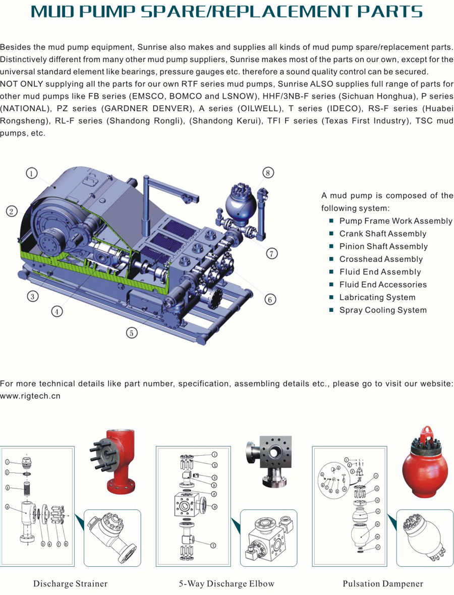
A Mud Pump may have many changeable parts, such as liner, piston, extension rod, pulsation dampener, valve, clamp, etc. Lake Petro could provide 100% interchangeable parts of many common brands of pump. We offer Liners with Ceramic (Zirconia and Aluminium oxide) and Steel (Metal and Bi-metal) materials. Piston assembly is the important spare parts and expendable parts of oil drilling mud pumps. Mud pump valve assy include valve body, valve seat, valve insert (valve rubber ). Pulsation Dampener is usually installed on the discharge line to reduce the fluctuation of pressure and displacement of the drilling mud pump. Fluid End Module is an important component of the hydraulic pump end of the mud pump.
No, it is currently FREE to enter our paved self-service parts lot. We do require a state-issued picture ID, and that you sign a waiver to enter the yard. This is required for insurance purposes.
Yes, if you are 16 to 17 years old, you can enter the self-service yard by completing and bringing this form. Click here to download, print, and bring with you. You’ll also need a government-issued picture ID.
You can bring your tools and a cart. We DO NOT allow torches and jacks in the yard. The cars are already raised on stands to help you get the parts you need. We also provide an engine hoist and wheelbarrows for your convenience in the yard.
We’ll do one better; we’ll email you and send you a text message when a car you’re looking for arrives in our 400 plus car inventory. We add 30 to 40 new cars to the lot everyday.
Starting in the summer of 2014 we began a multi-million dollar makeoverof the yard. It involved the paving of all 9 acres of our self-service auto parts lot and auto recycling facility.
Yes, you can get an Instant Quote to see just how much your old junk car is worth. We buy all makes and model of junk cars. We’ll even send a tow truck for free.
No title, no problem. We’ll still purchase your vehicle. There is a deduction to the price if you are missing the title. Please contact us at 630-860-2000 for more details.
All the fluids and other materials are drained, disposed, and recycled in an environmentally friendly way. We were green before green was cool. We process more than 2,000 tons of crushed cars every month. Roughly 85 percent of the parts that make up a car are recycled.
The classic Chicagoland commercial ran for 30 years. It was replaced on May 1, 2015 with a new commercial. With an updated paved self-service used car parts lot, and an updated parts department, it was also time to update the commercial.

If you work in oil and natural gas, you know what the two most valuable resources are – Time and Money. With our new Parts on Demand program, you can save more of both.
As part of Experience 360, our Parts on Demand program lets you manage your replacement parts inventory at your regional location, pump site, or even via GD Energy Products Parts on Demand mobile trailers.
These Frac and Mud Pump Consumables are OEM-certified parts, designed, manufactured and tested by our Pump experts, and proven to maximize the performance on your operation. Our parts are always available, ensuring you have what you need, whenever and wherever you need it.


 8613371530291