
plasterers quick fill mud pump free sample

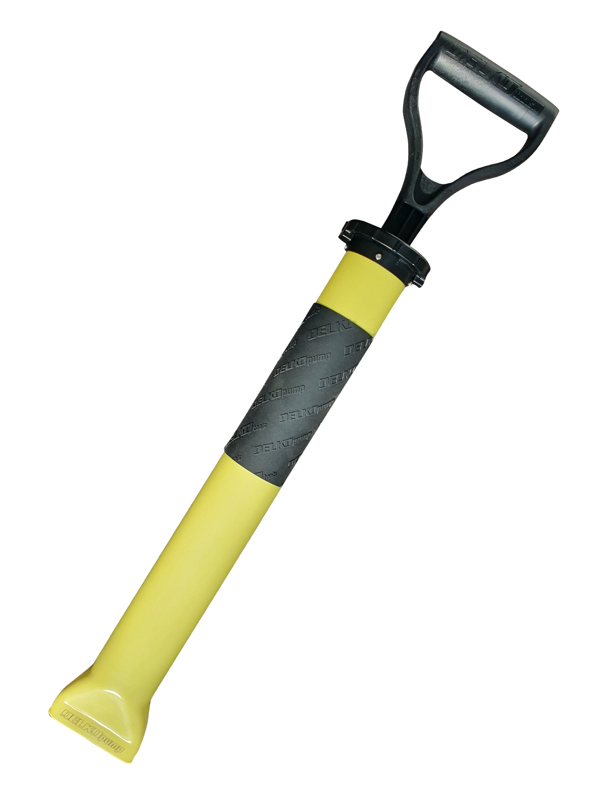
What a workhorse this tool is. Built to perform in the toughest environment, our pump smoothly and quickly fills your tools. With a 20 degree angle, the handle acts as a lever and keeps the operator from having to reach as far as other models on the market.FEATURES:

The Wallboard Tools Speed Filler Pump is an economical, mechanical loading and filling solution. It features a specially shaped flat nozzle end that fits the mouths of Flat Boxes for fast filling – and the best part? It rinses clean in just seconds.

This invention relates to a system for alternately filling two different types of drywall mud or wall board joint compound applicator devices in a single system set up and a diverter valve for the system which is adapted to handle drywall mud in a viscous, semi-liquid state ready for application to seams and to taped seams between adjacently disposed drywall panels.
Systems for delivering moist, flowable joint compound under pressure from an open top container to a single type of joint compound applicator device have long been known and used in the prior art. One such prior art system includes a manually operable hand pump having a lower body portion disposed in a container of viscous, semi-liquid joint compound and a tube known as a gooseneck having an upper inlet end connected directly to a discharge port on an upper body portion of the pump. A lower end portion of the tube rests on a floor and has an upwardly opening outlet end into which a charging port of a conventional bazooka type of drywall applicator device can be inserted for filling preparatory to using the bazooka to fill a seam between adjacently disposed drywall panels with drywall mud followed by applying a tape strip along and over the seam.
To operate the prior art system, a pump handle of the pump is manually operated to pump drywall mud from the container directly through the gooseneck and, thence, into a lower end of the bazooka. The filled bazooka is then removed from the outlet end of the gooseneck and is used to fill and tape the seams between adjacent drywall panels until the drywall mud containing barrel of the bazooka is empty, or nearly so, at which point it must be recharged. After recharging the bazooka and continuing on with the filling and taping of seams, it is desirable to charge or fill other types of drywall mud applicator devices such as flat boxes, for use in applying successive layers of mud to flat seams that have already been filled and taped with the bazooka in order to conceal the tape and level or even out the seam so as to effectively hide it from view on the finished wall. Also, after recharging the bazooka, and continuing on with that work, it is desirable to fill corner boxes with drywall mud for use in filling in and leveling and smoothing out inside right angle corners and in covering the tape strip previously applied thereover with the bazooka.
A problem encountered with such filling systems for drywall mud applicator devices is that, once the bazooka has been filled, it is necessary to disconnect the gooseneck from the pump in order to attach a corner box adapter to pump discharge port for filling of the corner box. In order to fill the flat box, a so-called T-adapter must be inserted into the corner box adapter now on the pump discharge port. After filling the corner box and/or the flat box as necessary, the corner box adapter must then be removed from the pump discharge port and the gooseneck must be reattached in order to thereafter refill the bazooka.
The successive breaking down and modifying of the prior art system to alternately accommodate the bazooka for filling and, then, the flat and corner boxes for filling is both time consuming and messy. Indeed, it would be desirable to have a system for supplying drywall mud to fill the bazooka and, then, the flat and corner boxes without having to continually remove and replace the gooseneck and corner box adapter.
By means of our invention, these and other difficulties encountered using prior art systems for alternately filling bazooka and box type drywall mud applicator devices is substantially eliminated.
It is an object of our invention to provide a system for supplying drywall mud in a viscous, semi-liquid state from a container for alternately filling at least two different types of drywall mud applicator devices.
It is a further object of our invention to provide such a system that permits the alternate filling of bazooka and box type drywall mud applicator devices without the necessity of removing and reinstalling a gooseneck tube and corner box adapter from and in the system.
It is another object of our invention to provide a two-way diverter valve for handling mud when in a viscous, semi-liquid state ready for application to seams and to taped seams between adjacently disposed drywall panels.
Briefly, in accordance with our invention, there is provided a system for supplying drywall mud in a viscous, semi-liquid state from a container for alternately filling at least two different types of drywall mud applicator devices. The system includes a pump adapted for placement at least partially within a quantity of drywall mud disposed in a container for pumping the drywall mud from the container to a drywall mud applicator device. The system further includes a diverter valve adapted for handling drywall mud including a housing, an inlet port connected to a discharge port of the pump, and at least two outlet ports which are alternately switchable into and out of communication with the valve inlet port. Each of the valve outlet ports is adapted for communication with a different type of drywall mud applicator device for alternately filling each said device.
FIG. 1 shows an exploded perspective view of a drywall joint compound delivery system for use in filling various joint compound applicator devices, thus illustrating a preferred embodiment of our invention.
FIGS. 2-4 show perspective views of a corner box, a pump outlet port adapter and a flat box, respectively, all being prior art devices used in and with conventional drywall joint compound delivery systems.
Referring now to the drawings figures, there is shown, in a preferred embodiment of our invention, a system, generally designated 10, for delivering drywall joint compound, sometimes referred to as drywall mud, in a moist, semi-liquid form, to various conventional applicator devices. One of such applicator devices is known in the trade as a bazooka 12 (FIG. 1), and comprises an elongated, hand held device conventionally used to apply drywall mud along a seam between adjacent drywall panels and to immediately thereafter, apply a tape strip over the seam, all in a single pass of a discharge port of the bazooka along and over the seam. Another of such applicator devices is a flat box 14 (FIG. 4) which is used to cover the tape strip, as applied over a flat seam between two adjacent drywall panels lying in a single plane, with drywall mud. Yet another of such devices is a corner box 16 (FIG. 3) which is used to apply drywall mud to cover a tape strip which seals a seam along an inside corner between two adjacent drywall panels disposed at right angles to one another.
First, a batch of drywall mud is prepared to a proper consistency in a suitable open top container or bucket 18 for application to drywall in a manner well known in the prior art Next, the body of a conventional drywall hand pump 20 is lowered into the drywall mud disposed in the container 18. A conventional brace or bracket 22 attached to an upper end portion of the pump 18, hangs over an outside surface of the container 20 as shown in FIG. 1. The bracket 22 contains a foot plate 24 which is held down against a container supporting surface by a foot of a worker to stabilize the container 18 while a pump handle 26 is operated to deliver drywall mud to a pump discharge port 28.
In the prior art, drywall mud is conventionally delivered from the pump discharge port 28 directly to a tube known as a gooseneck 30 in order to fill the bazooka 12. But, to thereafter fill boxes 14 and 16, the gooseneck 30 must first be disconnected from the pump discharge port 34 and the adapter 29 must then be attached to the port 34. In our system, the drywall mud is delivered from the pump discharge port through a gasket 32, which is shaped to conform and attach to a flange 34 on the pump discharge port 28, to one side port 35 (See FIG. 7) of a two-way drywall mud diverter valve, generally designated 36. A side port 38 on an opposite side of the diverter valve 36 from the side port 35 is connected through a gasket 40 (FIG. 1) to an inlet end 42 of the gooseneck 30. An outlet end 44 of the gooseneck delivers drywall mud upwardly to an inlet port 46 of the bazooka 12 to fill the latter when a valve gate, generally designated 50, of the diverter valve 36 is positioned as shown in FIG. 6. The gasket 32 is fastened against the pump discharge port flange 34 with suitable treaded fasteners such as machine screws and hex nuts. The gasket 40 is shaped to conform to a flange 52 on the inlet end 42 of the gooseneck 30 and is likewise, fastened to the flange with suitable threaded fasteners, such as machine screws and hex nuts.
With the valve gate 50 turned as shown in FIG. 7, the path of flow of drywall mud through the valve 36 is from the side port 35 into an elongated outlet tube 54 which is sized to closely fit onto an inlet port 56 (FIG. 2) of the corner box 16. Accordingly, either before or after filling the bazooka 12 through the gooseneck 30, the valve gate 50 is simply rotated ninety degrees from that filling position, to permit directly connecting the corner box 16 to the outlet tube 54 for filling of the corner box with drywall mud from the pump 20 through the diverter valve 36. To fill the conventional flat box 14, a conventional flat box adapter 58 (See FIG. 1) is inserted into an outer end of the outlet tube 54 as indicated by a centerline 60, the opposite end 62 of which is inserted into an elongated slot 64 (See FIG. 4) of the flat box. Again, the valve gate 50 is positioned as in FIG. 7 for drywall mud flow from the side port 35 to the outlet tube 54.
The diverter valve 36 is preferably constructed of a suitable molded plastic such as, for an example, polyvinylchloride or a suitable metal. In the preferred embodiment of our invention, the mating valve 36 includes a housing having two mating portions 37 aand 37 b, as seen in FIGS. 6 and 7. Each of the portions 37 aand 37 bcontains a semi-spherical interior portion 66 which, when mated together as shown in FIG. 5, form a spherically shaped hollow seat closely conforming to and around a ball shaped portion 68 of the valve gate 50. A handle 70 formed on one end of a stem 72 permits the valve gate 50 to be rotated so as to rotate the ball shaped portion 68 in the valve seat. The ball shaped portion 68 contains a hollow partially cylindrically shaped passage 74 which is opened along one side thereof. With the valve gate 50 positioned as shown in FIG. 7, drywall mud is pumped into the side port 35 and into the open side of the passage 74 in the ball portion 68 from whence it is directed into the outlet tube 54 for direct filling of the corner box 16 or for filling of the flat box 14 through the adapter 58. But with the ball portion 68 of the valve gate 50 positioned as shown in FIG. 6, drywall mud from the pump 20 is introduced into the side port 35 and travels along the passage 74 to the side port 38 for introduction to the gooseneck 30 and, ultimately, to the bazooka 12. Positioned as shown in FIG. 6, the spherical side of the ball shaped portion 68 blocks an entrance 76 to the outlet tube 54.
To seal the valve portions 37 aand 37 bto prevent leakage of drywall mud through the resulting seams, a tongue and groove arrangement 106 is used as shown in FIG. 5. Along the perimeter of 14
Referring now to FIGS. 10-11, there is shown an alternative valve gate, generally designated 90, which can be used in the valve 36 of the previous example in place of the valve gate 50. The gate 90 is manually rotatable on its longitudinal axis, which extends through a stem 92, by means of a handle 94. A ball shaped portion 96 is adapted to rotate within the semi-spherical portions 66 of the housing portions 37 aand 37 bof FIGS. 6-7 when the housing portions are adjoined over the ball shaped portion similar to FIG. 5. The portion 96 contains a hollow cylindrical shaped passage 98 therethrough having openings 100 and 102 on opposite sides thereof as shown in FIG. 10. A third opening 104 communicates with a central portion of the passageway 98 (See FIG. 11). Accordingly, the valve gate 90 permits passage of drywall mud straight through the passage 98 from one to the other of the openings 100 and 102 to feed mud from the pump discharge port 28 to the gooseneck 30 when properly positioned in the valve 36 of FIG. 1. When the valve gate 90 is turned ninety degrees from that position on its longitudinal axis, the pump discharge port 28 will then communicate through the opening 104 to one of the ports 100 or 102 with the tube 54. Accordingly, the alternative valve gate 90 also permits filling of either the gooseneck 30 or the boxes 14 and 16 depending upon a simple manual adjustment of the valve handle 99 and stem 92.
Examine pool surfaces to identify conditions that might interfere with proper bonding of coating. Look for algae, mold, mildew, dirt, paint, mortar droppings, efflorescence, patching compounds, loose tile, cracked plaster, et cetera. Clean pool surfaces of all material that might interfere with proper bonding of coatings. Clean with high pressure water or by sand blasting. Wash with chlorine until algae, mold, and mildew are gone. Wash oil and grease spots using tri-sodium phosphate or equivalent and water soak if necessary. Remove all cleaning solutions via high pressure-washing. Identify hollow spots in plaster by sounding. Remove and repair all hollow and de-laminated plaster. Saw cut an area three (3) inches around bad spots and remove plaster inside the saw cut. Undercut the edges of remaining plaster. Fill holes with specified patching cement SGM HSR High Strength Render to a level of existing plaster. Remove loose tile and fittings; undercut existing plaster two (2) inches below the tile line, and around return lines and fittings to a depth of 3/8 inch. Stop water penetration from outside pool. Plug cracks and leaks around fittings using hydraulic cement (SGM Dynamite Pool Patch). Etch cleaned surface with muriatic acid solution. Use concentration necessary to clean and roughen surface; smooth surfaces may require higher concentration. Neutralize surface with solution of baking soda and water to neutralize acid, which can cause bond failure. Remove remaining acid solutions via high pressure-washing. Plug pool inlets and outlets to prevent clogging with expandable plugs or threaded caps. Mark location of fittings using tape on coping or on a measured drawing. Place sump pump at main drain to remove all running and standing water. Do not begin installation until concrete pool shell has cured at least twenty-eight (28) days. For renovation projects (plastering over an existing plaster pool finish) and poured or formed concrete shells apply BOND-KOTE® as directed. Each unit of BOND-KOTE® consists of one (1) five-gallon pail of BOND-KOTE® resin and two (2) 65 lbs. bags of BOND-KOTE® powder, and will cover approximately 500 square feet. Mix one (1) 65 lbs. bag of BOND-KOTE® powder to ½ pail of BOND-KOTE® resin. Coat existing plaster using a 1¼ inch nap paint roller; create a rough stippled texture by going over the area a second time with roller. Allow BOND-KOTE® to cure for at least six (6) hours before plastering. Plaster should be applied to BOND-KOTE® within three (3) to five (5) days. If left for a longer period before finish is applied, ensure BOND-KOTE® is clean and free of dirt, efflorescence, and other contaminants. If necessary, clean BOND-KOTE® by brushing vigorously while spraying with water; chlorine may be used as needed.
River Rok® is made in batches of 4,000 to 20,000 lbs. (1,800 to 9,000 kg) using natural ingredients. For this reason there will be variations in shade between batches. Batch numbers are printed on the ends of each individual bag. It is important the user follow these instructions carefully to ensure the most consistent color throughout the pool. Jobsite additives, such as calcium chloride solutions, pump-aides, or bonding agents can affect the color of this product. For best results mix product using only cool, clean potable water. If adding any other approved additives, hold a portion of the mix water to the additives, screen and add the final amount to mixer. Additives should be introduced at the end of the mixing process. Ensure that the additives are mixed with water and pre-dissolved.
The shelf life of River Rok® is up to one (1) year in an unopened, properly stored container. River Rok® can be mixed by using low-speed paddle mixer, low RPM drill with mud paddle, ribbon blender, or concrete plaster mixer. Measure and add 1½ to two (2) gallons (5.7 to 7.6 L) of clean potable water to mixer.
Start mixer and add River Rok® as quickly as possible to ensure that all the material has the proper mix time. Mix for a minimum of five (5) minutes but no more than ten (10) minutes. This ensures even distribution of aggregates and increases the working time of the plaster. Insufficient mix time will result in uneven setting and shade variations. Too much mix time will produce an overall weaker plaster and may entrain undesirable air bubbles. As a rule of thumb, mix for only the amount of time required to produce a consistent, homogenous mix. Calcium chloride may be used as an accelerator. It must be fully dissolved in water allowing impurities to settle out. Pour off the solution from the top being careful not to add impurities to the mix. The impurities found in calcium chloride flake and pellets have been known to cause discoloration in pool plaster. No more than two (2) percent by weight of cement (about ½ lb. per bag) can be used. Overuse may cause discoloration.
Although it is not necessary to use a plaster pump, many contractors do. Included here are some helpful hints for successful pumping. Increase the size of the pump manifold from three (3) inches to four (4) inches. Change the valve ball from plastic to steel to improve longevity. Set plaster pump to the lowest gear by moving the belt. Always begin pumping with a full stroke on the main piston. This is accomplished by advancing the wheel until the cam is at its highest position. Prepare a slurry of cement and water or pump aid and run it through the pump first to prime the pump and lubricate the hoses. Pour the mixed plaster slowly into the pump hopper. Do not pour all the material in at once. Agitate the material in the hopper to prevent separation of the cement and aggregate. Avoid unnecessary stopping during the pumping process. River Rok aggregate will tend to settle in the pump manifold and hoses when the pump is stopped. Agitate the remaining material left in the hopper to reduce clogging. Do not try to clear a blockage using the pump. Disassemble and clean the manifold and hoses when clogged. Do not over-water mix. This will only cause the material to separate, clogging the pump and hoses.
NOTE: Hot, dry shells will cause rapid setting of the plaster and result in check or shrinkage cracking and de-lamination. All materials and effected areas should remain above 50°F / 10°C (fifty degrees Fahrenheit / ten degrees Celsius) or below 100°F / 38°C (100 degrees Fahrenheit / 38 degrees Celsius) 24-hours prior and 72-hours after placement. Discard unmixed material (lumps). Apply plaster liberally with flat side of trowel using sufficient pressure to key in a scratch coat on the vertical surfaces. Beginning with the shady walls and working to the sunny walls, trowel a scratch coat onto the walls and allow to set up until it becomes tacky. The set time will vary according to the temperature and humidity. Once the scratch coat has become tacky, apply a finish coat to the entire pool surface beginning in bowl area and working toward the shallow end, troweling and blending walls and floor together to achieve a seamless appearance while working to a final thickness of one-half inch (10 mm—12 mm). Uniform troweling will help to ensure even exposure, reduce washouts and produce a comfortable slip-resistant finish. The technique of “slick troweling” is recommended. During application make several passes with pool trowels to compact the aggregate and ensure a smooth dense finish. In this process the cement paste is brought to the surface during troweling, then removed with the trowel. This produces a slick surface and minimizes the exposure needed. Small amounts of lubrication water may be necessary for smoothing out and compacting the finish in this process. The aggregate can be seen through a thin film of cement paste after troweling is complete. Special attention must be given to the filling in of spike holes. The applicator must be careful to fill all spike holes with River Rok aggregate to avoid visible spike holes. Extra care must be taken to ensure proper troweling in the coves and corners. Specialty trowels are required for these areas. Insufficient troweling in these areas will result in roughness and washouts (loss of cement and aggregate) during the exposure process.
When the River Rok® has lost its sheen or is no longer damp, it may be ready for exposure with soft bristle brushes and water. The material must be sufficiently set up to allow applicators to walk on the floor without leaving footprints. Wear white cotton socks or foam shoes when exposing River Rok®. Boots and bare feet are not recommended. Test the plaster for readiness by carefully washing a small area with a soft bristle brush. If the cream washes away without losing aggregate the exposure process may begin. Starting with sunny or fast setting areas begin washing away cement paste with water and brushes. Use a bucket first then progress to a soft flow of water from a garden hose as the material begins to harden. Begin using stiff bristle brushes as the set progresses. Examine the plaster for hot spots that may be setting quickly. Mist these areas with water to allow longer exposure time. Over-cured cement paste will not remove easily and may require stiff bristle brushes to remove. Avoid slow setting areas like shady walls and the bowl. Washing too soon in these areas will cause washouts. If an area washes out it must be re-troweled immediately. Keep some extra River Rok® mixed up for use in patching washout areas. Keep a sump pump running in the main drain at all times to discharge the wash solution. Dispose of wash as directed by local requirements. Avoid leaving hoses, buckets, or any other items on the plaster during exposure. Any object left on the plaster during this critical phase may leave a “shadow” on the surface. In the event of shadowing, heat may be carefully applied to remove the discoloration. When all of the cement paste has been removed from the surface uniformly, the brushing phase is complete. If done thoroughly, this will complete the exposure process. If desired, the water washing may be followed by a light acid-wash to further enhance exposure of the River Rok finish. This is preferably done the same day after allowing for additional drying time, or early the following day.
This technique is commonly used in cold climates or when the plasterers lack sufficient experience to undertake water washing. It is easier to do but can produce a less uniform finish. After troweling, allow the plaster to fully set up. This may take anywhere from one to a few hours or overnight, depending on local job site conditions. Begin acid washing by using a twenty-five (25) percent solution of muriatic acid (higher concentrations may be needed for stubborn areas) and water to remove the cement film that may remain on the surface. Increase the concentration of the acid solution as needed. Proper safety equipment must be worn at all times. Begin washing the bowl first and work up to the shallow end. Following this procedure will minimize “rivers” or streaks on the floor. Acid wash walls and steps last. Do not allow acid wash solution to puddle in the bowl area. Use a sump pump to constantly discard the run off after it is diluted and neutralized. The use of an acid wash additive to reduce fumes and ensure uniform coverage is highly recommended. Neutralize and discard the wash solution according to local requirements. Neutralize acid remaining on the River Rok® with “soda ash” and water to avoid discoloration.
This technique is sometimes used after water washing instead of a standard acid wash. It is also used in areas where the fill water is high in alkalinity and or hardness. When use alone without water washing this technique produces the least desirable results. It will not remove all of the cement paste evenly and my result in a streaked appearance. Remove all metal such as ladders and lights from the pool and turn off the circulation system. After filling the pool test the alkalinity to determine the amount of muriatic acid needed to lower the total alkalinity to zero. Distribute the acid evenly throughout the pool. Brush the pool thoroughly over the entire surface twice daily for three (3) days. Add a sequestering agent and raise the pH to the proper level with soda ash. Start the circulation system and follow the start-up instructions.
Hard trowel pool to uniform smooth finish. Let finish air dry for one (1) to three (3) hours after completion. This technique begins by filling the pool with eight (8) to ten (10) inches of water. This water will buffer the acid solution during the exposure process. Acid wash with 100 percent muriatic acid starting with walls working down to the bowl. Leave acid on for approximately one (1) to two (2) minutes before rinsing off with a hose. Keep constant water on the floor to diffuse acid solution avoiding streaks. Keep acid-washed areas wet through the entire process or cement paste will re-set. Complete acid wash on floor and bowl of the pool and finish by pumping out water. Begin the power washing phase with 2,500 PSI machine using a 45-degree nozzle. Keep the tip twelve (12) to eighteen (18) inches away from the surface perpendicular to the plaster finish. Power wash surface with approximately twenty (20) percent overlap to ensure complete exposure. Start power washing walls from tile line thru cove of the pool and finish with the floor. Pump out the remaining water, install main drain covers, lights, and fittings.
In accordance with the National Plasterers Council (NPC) standards, it is recommended that the following pool and spa water chemistry conditions be maintained on an ongoing basis for the longevity of the interior pool and spa finish. These values are important to prevent corrosion, deterioration, discoloration, scaling or other problems. For more information refer to your local agency having jurisdiction or NPC. Follow recommended fill and balancing procedures to ensure a successful start-up. Fill pool completely and without interruption with clean, potable water. The use of a filter during fill is strongly recommended. The initial fill water is the most important water that the pool will receive and must be tested, recorded and adjusted according to the following parameters by an experienced pool professional. For the first thirty days (30) the pH and alkalinity must be monitored and adjusted (if applicable) every three (3) to five (5) days. All other chemicals monitored and adjusted (if applicable) every seven (7) to ten (10) days. The pool water must be tested regularly and documented monthly by a reputable company using a computerized system. Monitoring the pool water regularly will not only affect the new finish but will keep it looking new. Improper water chemistry will void the limited residential / commercial warranty. It is recommended that a quality sequestering agent be used in the initial start-up in accordance with the manufacturer’s instructions and then a recommended maintenance dosage per the sequestering agent’s manufacturer instructions.
FIRST DAY: Add sequestering agent upon initial fill per manufacturer’s instructions. Adjust pH to 7.2 – 7.6 and total alkalinity to 80 -120 PPM. Maintain calcium hardness at a minimum of 125 PPM for the first three days, then adjust to 200-400 PPM thereafter. Dissolve chemicals completely in water and disperse throughout pool.
Adjust circulating pump timer to normal operating hours. Brush the pool walls and floor daily for the first two (2) weeks. Do not vacuum pool with wheeled vacuum for 14 days. Putting a wheel cleaner in the pool prematurely can cause wheel marks/ tracks to show up on the pool finish. Do not install an automatic pool cleaner for 28 days. No salt should be added for 28 days. Please make sure the water pH and alkalinity is balanced prior to the use of salt chlorine generators.
Examine pool surfaces to identify conditions that might interfere with the proper bonding of coating. Look for algae, mold, mildew, dirt, paint, mortar droppings, efflorescence, patching compounds, loose tile, cracked plaster, et cetera. Clean pool surfaces of all material that might interfere with the proper bonding of coatings. Clean with high-pressure water or by sandblasting. Wash with chlorine until algae, mold, and mildew are gone. Remove oil and grease spots using tri-sodium phosphate or equivalent and water; soak if necessary. Remove all cleaning solutions via high pressure- washing. Identify hollow spots in plaster by sounding. Remove and repair all hollow and de-laminated plaster. Saw cut an area three (3) inches around bad spots and remove plaster inside the saw cut. Undercut the edges of the remaining plaster. Fill holes with specified patching cement SGM HSR High Strength Render to a level of existing plaster. Remove loose tile and fittings; undercut existing plaster two (2) inches below the tile line, and around return lines and fittings to a depth of 3/8 inch. Stop water penetration from the outside pool. Plug cracks and leaks around fittings using hydraulic cement (SGM Dynamite Pool Patch). Etch cleaned the surface with a muriatic acid solution. Use concentration necessary to clean and roughen the surface; smooth surfaces may require higher concentration. Neutralize surface with a solution of baking soda and water to eliminate acid residue, which can cause bond failure. Remove remaining acid solutions via high pressure-washing. Plug pool inlets and outlets to prevent clogging with expandable plugs or threaded caps. Mark location of fittings using tape on coping or on a measured drawing. Place the sump pump at the main drain to remove all running and standing water. Do not begin installation until the concrete pool shell has cured at least twenty-eight (28) days. For renovation projects (plastering over an existing plaster pool finish) and poured or formed concrete shells apply SGM BOND-KOTE® as directed. Allow BOND-KOTE® to cure for at least six (6) hours before plastering. Plaster should be applied to BOND-KOTE® within three (3) to five (5) days. If left for a longer period before the finish is applied, ensure BOND-KOTE® is clean and free of dirt, efflorescence, and other contaminants. If necessary, clean BOND-KOTE® by brushing vigorously while spraying with water; chlorine may be used as needed.
The shelf life of Pool Brite is up to one (1) year in the unopened, properly stored container. Pool Brite can be mixed by using a low-speed paddle mixer, low RPM drill with mud paddle, ribbon blender, or concrete plaster mixer. Measure and add two (2) to 2.5 gallons of clean potable water to mixer.
Start the mixer and add Pool Brite® as quickly as possible to ensure that all the material has the proper mix time. Mix for a minimum of five (5) minutes but no more than ten (10) minutes. This ensures even distribution of aggregates and increases the working time of the plaster. Insufficient mix time will result in uneven setting and shade variations. Too much mix time will produce an overall weaker plaster and may entrain undesirable air bubbles. As a rule of thumb, mix for only the amount of time required to produce a consistent, homogenous mix. Calcium chloride may be used as an accelerator. It must be fully dissolved in water allowing impurities to settle out. Pour off the solution from the top being careful not to add impurities to the mix. The impurities found in calcium chloride flake and pellets have been known to cause discoloration in pool plaster. No more than two (2) percent by weight of cement (about ½ lb. per bag) can be used. Overuse may cause discoloration.
Although it is not necessary to use a plaster pump, many contractors do. Included here are some helpful hints for successful pumping. Increase the size of the pump manifold from three (3) inches to four (4) inches. Change the valve ball from plastic to steel to improve longevity. Set the plaster pump to the lowest gear by moving the belt. Always begin pumping with a full stroke on the main piston. This is accomplished by advancing the wheel until the cam is at its highest position. Prepare a slurry of cement and water or pump aid and run it through the pump first to prime the pump and lubricate the hoses. Pour the mixed plaster slowly into the pump hopper. Do not pour all the material in at once. Agitate the material in the hopper to prevent separation of the cement and aggregate. Avoid unnecessary stopping during the pumping process. Pool Brite aggregate will tend to settle in the pump manifold and hoses when the pump is stopped. Agitate the remaining material left in the hopper to reduce clogging. Do not try to clear a blockage using the pump. Disassemble and clean the manifold and hoses when clogged. Do not over-water mix. This will only cause the material to separate, clogging the pump and hoses.
The substrate should be cool and damp but not dripping wet. Mist shell with cool, clean potable water. Non-absorbed water may be removed by using sponges and/or air. Standing water will weaken Pool Brite and may cause washouts. Note: Hot, dry shells will cause the rapid setting of the plaster and result in check or shrinkage cracking and de-lamination. All materials and effected areas should remain above 50°F / 10°C (fifty degrees Fahrenheit / ten degrees Celsius) or below 100°F / 38°C (100 degrees Fahrenheit / 38 degrees Celsius) 24-hours prior and 72-hours after placement. Discard unmixed material (lumps). Apply plaster liberally with the flat side of the trowel using sufficient pressure to key in a scratch coat on the vertical surfaces. Beginning with the shady walls and working to the sunny walls, trowel a scratch coat on the walls and allow to set up until it becomes tacky. The set time will vary according to temperature and humidity. Once the scratch coat has become tacky, apply a finish coat to the entire pool surface beginning in bowl area and working toward the shallow end, troweling and blending walls and floor together to achieve a seamless appearance while working to a final thickness of one-half (½) inch (10 mm—12 mm). Uniform troweling will help to ensure even exposure, reduce washouts and produce a comfortable slip-resistant finish. The technique of “slick troweling” is recommended. During the application, make several passes with pool trowels to compact the aggregate and ensure a smooth dense finish. In this process, the cement paste is brought to the surface during troweling and is removed with the trowel. This produces a slick surface and minimizes the exposure needed. Small amounts of lubrication water may be necessary for smoothing out and compacting the finish in this process. The aggregate can be seen through a thin film of cement paste after troweling is complete. Special attention must be given to the filling in of spike holes. The applicator must be careful to fill all spike holes with Pool Brite aggregate to avoid visible spike holes. Extra care must be taken to ensure proper troweling in the coves and corners. Specialty trowels are required for these areas. Insufficient troweling in these areas will result in roughness and washouts (loss of cement and aggregate) during the exposure process.
In accordance with National Plasterers Council (NPC) standards, it is recommended that the following pool and spa water chemistry conditions be maintained on an ongoing basis for the longevity of the interior pool and spa finish. These values are important to prevent corrosion, deterioration, discoloration, scaling or other problems. For more information refer to your local agency having jurisdiction or NPC. Follow recommended fill and balancing procedures to ensure a successful start-up. Fill pool completely and without interruption with clean, potable water. The use of a filter during fill is strongly recommended. The initial fill water is the most important water that the pool will receive and must be tested, recorded and adjusted according to the following parameters by an experienced pool professional. For the first thirty days (30) the pH and alkalinity must be monitored and adjusted (if applicable) every three (3) to five (5) days. All other chemicals monitored and adjusted (if applicable) every seven (7) to ten (10) days. The pool water must be tested regularly and documented monthly by a reputable company using a computerized system. Monitoring the pool water regularly will not only affect the new finish but will keep it looking new. Improper water chemistry will void the limited residential / commercial warranty. It is recommended that a quality sequestering agent be used in the initial start-up in accordance with the manufacturer’s instructions and then a recommended maintenance dosage per the sequestering agent’s manufacturer instructions.
FIRST DAY: Add sequestering agent upon initial fill per manufacturer’s instructions. Adjust pH to 7.2 – 7.6 and total alkalinity to 80 -120 PPM. Maintain calcium hardness at a minimum of 125 PPM for the first three days, then adjust to 200-400 PPM thereafter. Dissolve chemicals completely in water and disperse throughout pool.
Adjust circulating pump timer to normal operating hours. Brush the pool walls and floor daily for the first two (2) weeks. Do not vacuum pool with wheeled vacuum for 14 days. Putting a wheel cleaner in the pool prematurely can cause wheel marks/ tracks to show up on the pool finish. Do not install an automatic pool cleaner for 28 days. No salt should be added for 28 days. Please make sure the water pH and alkalinity is balanced prior to the use of salt chlorine generators.
Pool Brite®’s lifetime will be greatly enhanced through proper and regular maintenance. Test and record water chemistry values once a week, and adjust as indicated per water-balance table recommendations. Brush the entire pool, walls, and floor weekly. Remove any debris and foreign materials immediately to prevent staining. Check and maintain filter, pump motor and skimmer baskets to maintain proper flow and filtering action. If unable to perform regular weekly maintenance, the services of a qualified licensed pool service professional should be obtained.
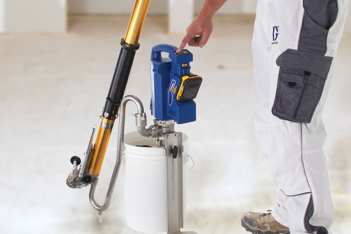
Finish every job more quickly and eliminate the need to hand pump again. Graco Cordless Drywall Mud Pumps let you fill all of your taping tools with the push of a button. With Standard Series or Pro Series pumps, there is a PowerFill for every business.
Before you start, make sure your wall is clean by removing bits of existing plaster, dust or wallpaper as you go and check the suction of your wall to make sure it isn’t too porous. If this is the case, it will suck the moisture out of the plaster so fast that it won’t have a chance to work before it dries. So, control the suction of your wall with water or PVA, which should satisfy the thirst of the wall, stopping it from stealing the moisture from your plaster too quick.
TIP – When plastering a room, try not to do two walls that are touching each other as you risk damaging one wall while plastering the other. Turn all radiators off in the room too, to stop the plaster drying too quick. Beginners should start on a small area first to ensure they’re getting the technique right, so start with an area which only takes 30 mins or less for the first coat.
It could be the case (especially if it’s your first time) that you haven’t gradually decreased the angle of your trowel as you moved along the wall, perhaps you flattened the trowel to the wall too soon or overcompensated and things got quite messy. If this is the case and you have ended up with lots of levels of thickness you can go over it again with a fairly flat trowel angled at about 10mm to flatten out where you’ve been. Combine the flatness of the trowel with firm pressure all the way through to flatten and fill in any holes.
If you’re going too quick and not flattening the trowel quickly enough, you may get the scraping effect which means the top edge of the trowel is coming away from the wall, so it needs to come in a bit. The secret here is to go slowly and keep an eye on the gap between the trowel and the wall, using a firm pressure as you go.
Also, when you plaster a wall, remember to try and remove annoying bits of grit straight away and make sure you keep everything clean. The next stage is to flatten the first coat off and give your trowel a quick clean. The sole purpose of this stage is to get your wall flat and knock the ridges back because if you don’t at this stage, you are just plastering over an already uneven wall once it has dried and this can only lead to an even more uneven, bumpy wall further down the line.
Perhaps try putting a small amount of plaster on a piece of off cut and work out how quickly it dries before you attempt a large section of your wall – after all, it’s when the wall has gone tacky (firm, but not hard) that the imperfections can be removed using a trowel. If the plaster has dried completely, only sanding the wall will remove the holes and ridges and this can be a painful and laborious task.
Any brush marks left in the corner can be lightly trowelled out – but again if it is really wet it may be better to leave until the next stage. You can use water at this point to get a good clean, but don’t flick too much water on your walls unless you need it, or you can end up with a slurry effect on the plaster. Pass the trowel over sections of the wall and look for hollow areas or holes, then work the plaster into them. Moving from left to right, cover the whole area, working the plaster around the wall to keep it flat and fill hollow areas.
Try these following steps to help you along… Use a trowel or scraper to fill the corner gap between the plaster walls with the first coat, making sure to scrape off any excess. Once the first coat is dry, use the trowel or scraper blade to take off any small ridges. Then, cut a piece of paper tape to the height of your wall. Fold the tape in half so there is a crease running down the centre of it. You can then apply a thin coat of plaster base coat to both sides of the internal corner and press the tape over the top.

It features a specially shaped flat nozzle end that fits the mouths of Flat Boxes for fast filling – and the best part? It rinses clean in just seconds.


 8613371530291