
positive displacement mud pump free sample

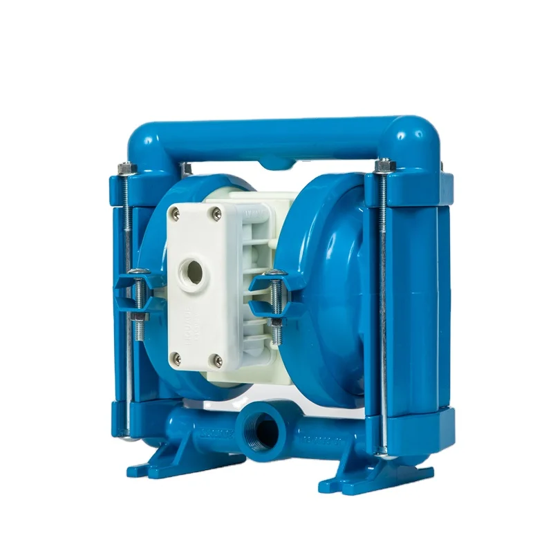
The 2,200-hp mud pump for offshore applications is a single-acting reciprocating triplex mud pump designed for high fluid flow rates, even at low operating speeds, and with a long stroke design. These features reduce the number of load reversals in critical components and increase the life of fluid end parts.
The pump’s critical components are strategically placed to make maintenance and inspection far easier and safer. The two-piece, quick-release piston rod lets you remove the piston without disturbing the liner, minimizing downtime when you’re replacing fluid parts.

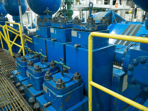
Positive displacements pumps are generally used on drilling rigs to pump high pressure and high volume of drilling fluids throughout a drilling system. There are several reasons why the positive displacement mud pumps are used on the rigs.
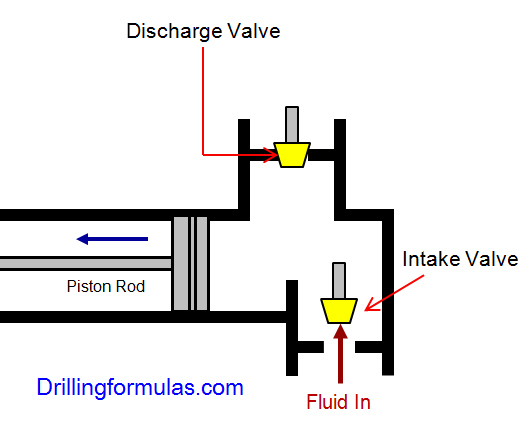
The duplex pumps (Figure 1) have two cylinders with double acting. It means that pistons move back and take in drilling mud through open intake valve and other sides of the same pistons, the pistons push mud out through the discharge valves.
When the piston rod is moved forward, one of intake valves is lift to allow fluid to come in and one of the discharge valve is pushed up therefore the drilling mud is pumped out of the pump (Figure 2).
On the other hand, when the piston rod is moved backward drilling fluid is still pumped. The other intake and discharge valve will be opened (Figure 3).
The triplex pumps have three cylinders with single acting. The pistons are moved back and pull in drilling mud through open intake valves. When the pistons are moved forward and the drilling fluid is pushed out through open discharge valves.
On the contrary when the piston rods are moved backward, the intake valve are opened allowing drilling fluid coming into the pump (Figure 6). This video below shows how a triplex mud pump works.
Because each pump has power rating limit as 1600 hp, this will limit capability of pump. It means that you cannot pump at high rate and high pressure over what the pump can do. Use of a small liner will increase discharge pressure however the flow rate is reduces. Conversely, if a bigger liner is used to deliver more flow rate, maximum pump pressure will decrease.
As you can see, you can have 7500 psi with 4.5” liner but the maximum flow rate is only 297 GPM. If the biggest size of liner (7.25”) is used, the pump pressure is only 3200 psi.
Finally, we hope that this article would give you more understanding about the general idea of drilling mud pumps. Please feel free to add more comments.

I’ve run into several instances of insufficient suction stabilization on rigs where a “standpipe” is installed off the suction manifold. The thought behind this design was to create a gas-over-fluid column for the reciprocating pump and eliminate cavitation.
When the standpipe is installed on the suction manifold’s deadhead side, there’s little opportunity to get fluid into all the cylinders to prevent cavitation. Also, the reciprocating pump and charge pump are not isolated.
The suction stabilizer’s compressible feature is designed to absorb the negative energies and promote smooth fluid flow. As a result, pump isolation is achieved between the charge pump and the reciprocating pump.
The isolation eliminates pump chatter, and because the reciprocating pump’s negative energies never reach the charge pump, the pump’s expendable life is extended.
Investing in suction stabilizers will ensure your pumps operate consistently and efficiently. They can also prevent most challenges related to pressure surges or pulsations in the most difficult piping environments.

A well-placed suction stabilizer can also prevent pump chatter. Pump chatter occurs when energy is exchanged between the quick opening and closing of the reciprocating pump’s valves and the hammer effect from the centrifugal pump. Pump isolation with suction stabilizers is achieved when the charge pumps are isolated from reciprocating pumps and vice versa. The results are a smooth flow of pumped media devoid of agitating energies present in the pumped fluid.

Look Inside Positive Displacement Motor: A comprehensive and valuable book written by a team of outstanding experts in this tool and published through SigmaQuadrant publishing. The Positive Displacement Motors covers the full spectrum of topics in terms of analysis and design of the downhole mud motor that serves the workhorse of the downhole drilling system for several decades. This book presents functional, operational and technical aspects of positive displacement motor. It provides a platform ideal to seasoned engineer, experienced researcher and other professionals involved in the drilling operations as it offers real insight into this simple but complex machine. It highlights the background and development of this tool
In 1990s, the trend of introducing new technologies for drilling high angle and horizontal wells and sidetracks continued. The introduction of these technologies, where PDM is one of the main elements of multifunctional complex technical, gained progress in oil and gas industry. In the last 10 years, new generation motors with improved technical and operational characteristics were introduced. Dr. Rene Moineau, a French engineer first invented and obtained several modified patents for a rotary type pump between 1930 and 1948.
The pumps he developed were extensively used in the world war planes as superchargers. In fact, Archimedes invented a pump that consisted of a spiral shaft which when turned by hand lifted water from lake. Moineau basically developed further Archimedean screw pump idea. The first commercial PDM was introduced to the petroleum industry in the late 1950s. Their use increased in the late 1960s for the directional drilling application. However, their use has accelerated greatly with the present coiled tubing drilling.

The Adtech Downhole Drilling Motor is a positive displacement hydraulic motor/pump powered by drilling rig mud or water. When the fluid is pumped through the tool the bit is turned at a speed proportional to the flow and remains relatively constant regardless of the load or developed horsepower. As weight is added to the motor and the bit start drilling the standpipe pressure will increase in direct proportion to the torque generated. This serves as a built-in indicator as to how the motor is performing, even if wall drag prevents an accurate response of the rig weight indicator.
Design: All housings of the Adtech motor are tightened with controlled torque (breakout machines) and are locked to minimize accidental backoffs. Prior to shipment out to the field, each tool is thoroughly inspected and tested on our mud pump testing station to guarantee long, trouble-free operation.
Is the motor sanded-up? An especially dirty hole of faulty float valve could have allowed solids to settle within the motor causing the drilling fluid to channel rather than turn the motor. Continuous pumping (15 minutes maximum) will sometimes correct such a condition. Also during this time slow rotation of the pipe (to the right) while gently tagging bottom will sometimes free the motor.
If none of the above (or other) corrective actions prove unsuccessful, it will be necessary to trip the tool from the hole. While tripping check for drill pipe and drill collar for washouts to be sure calculated flow was actually getting to the tool. Surface check the tool by pumping through at normal flow rates and watch for normal rotation. If the tool does not rotate pump through for 15 minutes to see if it clears itself. If the motor turns at about half its normal speed check the bypass valve again to be sure that it is actuating freely. Check for anything unusual, as for example, pieces of metal or rubber trapped in the bit, a bent bit sub, etc.
The Adtech motor, being a positive displacement motor, will run at a specific speed (RPM) for a specific volume (gal/min.) throughout. The required circulation rate as discussed under Specifications should be established prior to drilling and maintained throughout the drilling program for optimum tool performance. For duplex and triplex piston pumps, the flow rate depends on the length of the pump stroke, liner size, number of strokes per minute, and efficiency. For easy reference, the circulation rate for various sizes of pumps is shown in Appendixes F and G. For duplex pumps, these tables were prepared using 95% efficiency for under 40 strokes per minute and 90% efficiency for over 40 strokes per minute. The triplex pump information is shown at 100% efficiency.
The Adtech motor is designed to effectively handle most drilling fluids including lost circulation material. However, since the long term performance of the motor depends so heavily on the mud as its source of power more attention will be given to it here. Regular and complete testing of the mud is important not only to the prevention of damage to the motor but also to the success of drilling and maintaining the hole condition as well.
Particular attention should be given to the following items: Lost Circulation Material As a general rule anything the rig pump can handle can also be handled by the drilling motor. Care should be exercised however in adding these materials to the mud system so that the system is not slugged with large quantities at one time. These could become lodged within the motor or bit passageways. Also it is advisable to run the rig pumps with screens to avoid extra large debris from entering the system. Rags and tools accidentally dropped down the circulating system will severely plug and damage drilling motor.
Just like sand and abrasive solids will damage the rig surface equipment the drilling motor will likewise be adversely affected. If possible, desanders should always be used and kept working correctly. Maximum sand content should be no more than 2% by volume with a preferred content of less than 1%. It should be noted that the standard API measurement for sand considers particles only greater than 200 mesh in size. However, smaller particles, depending on their hardness and shape will remove approximately as much material as the courser sand. These finer particles will be found in the solids content of the mud and will have to be removed if present.
A mud motor (or drilling motor) is a progressive cavity positive displacement pump (PCPD) placed in the drill string to provide additional power to the bit while drilling. The PCPD pump uses drilling fluid (commonly referred to as drilling mud, or just mud) to create eccentric motion in the power section of the motor which is transferred as concentric power to the drill bit. The mud motor uses different rotor and stator configurations to provide optimum performance for the desired drilling operation, typically increasing the number of lobes and length of power assembly for greater horsepower. In certain applications, compressed air, or other gas, can be used for mud motor input power. Normal rotation of the bit while using a mud motor can be from 60 rpm to over 100 rpm.
Normal mud motor construction consists of a top sub, which connects the mud motor to the drill string; the power section, which consists of the rotor and stator; the transmission section, where the eccentric power from the rotor is transmitted as concentric power to the bit using a constant-velocity joint; the bearing assembly which protects the tool from off bottom and on bottom pressures; and the bottom sub which connects the mud motor to the bit.
A mud motor is described in terms of its number of stages, lobe ratio and external diameter. Stages are the number of full twists that the stator makes from one end to the other and the lobe ratio is the number of lobes on the stator, to the number of lobes on the rotor (the stator always has one more lobe than the rotor). A higher number of stages indicates a more powerful motor. A higher number of lobes indicates a higher torque output (for a given differential pressure), a lower number of lobes indicates a reduction in the torque produced but a faster bit rotation speed.
The use of mud motors is greatly dependent on financial efficiency. In straight vertical holes, the mud motor may be used solely for increased rate of penetration (ROP), or to minimize erosion and wear on the drill string, since the drill string does not need to be turned as fast.
The majority of mud motor use is in the drilling of directional holes. Although other methods may be used to steer the bit to the desired target zone, they are more time-consuming, which adds to the cost of the well. Mud motors can be configured to have a bend in them using different settings on the motor itself. Typical mud motors can be modified from 0 degrees to 4 degrees with approximately six increments in deviation per degree of bend. The amount of bend is determined by rate of climb needed to reach the target zone. By using a measurement while drilling (MWD) tool, a directional driller can steer the bit to the desired target zone.
The PCPD stator, which is a major component of the pump, is usually lined with an elastomer. Most of PCPD pump failures are due to this elastomer part. However, the operating conditions
The mud motor may be sensitive to fouling agents. This means that certain types of drilling fluids or additives may ruin the motor or lower its performance. One particular example, as mentioned above, would be the use of oil based mud with the mud motor. Over time the oil degrades the elastomers and the seals in the motor.

A plunger pump is a type of positive displacement pump where the high-pressure seal is stationary and a smooth cylindrical plunger slides through the seal. This makes them different from piston pumps and allows them to be used at higher pressures. This type of pump is often used to transfer municipal and industrial sewage.
Piston pumps and plunger pumps are positive displacement pumps that use a plunger or piston to move media through a cylindrical chamber. The plunger or piston is actuated by a steam powered, pneumatic, hydraulic, or electric drive.
Rotary piston and plunger pumps use a crank mechanism to create a reciprocating motion along an axis, which then builds pressure in a cylinder or working barrel to force gas or fluid through the pump. The pressure in the chamber actuates the valves at both the suction and discharge points. Plunger pumps are used in applications that could range from 70 to 2,070 bar (1,000 to 30,000 psi). Piston pumps are used in lower pressure applications. The volume of the fluid discharged is equal to the area of the plunger or piston, multiplied by its stroke length. The overall capacity of the piston pumps and plunger pumps can be calculated with the area of the piston or plunger, the stroke length, the number of pistons or plungers and the speed of the drive. The power needed from the drive is proportional to the pressure and capacity of the pump.
Seals are an integral part of piston pumps and plunger pumps to separate the power fluid from the medium that is being pumped. A stuffing box or packing is used to seal the joint between the vessel where the medium is transferred and the plunger or piston. A stuffing box may be composed of bushings, packing or seal rings, and a gland.
Plunger pumps" component materials are chosen for wear and contact with the type of medium. Component materials include bronze, brass, steel, stainless steel, iron, nickel alloy, or other material. For example, plunger pumps that function in general service or oil service applications often have an iron cylinder and plunger. The plunger, discharge valves, and suction valves come in contact with the transferred medium, and material choices are based on the fluid transferred. In power applications where continuous duty plunger pumps are needed, solid ceramic plungers may be used when in contact with water and oil, but may not be compatible for use with highly acidic media types.
Centrifugal pumps basically consist of a stationary pump casing and an impeller mounted on a rotating shaft. The pump casing provides a pressure boundary for the pump and contains channels to properly direct the suction and discharge flow. The pump casing has suction and discharge penetrations for the main flow path of the pump and normally has small drain and vent fittings to remove gases trapped in the pump casing or to drain the pump casing for maintenance.
Some centrifugal pumps contain diffusers. A diffuser is a set of stationary vanes that surround the impeller. The purpose of the diffuser is to increase the efficiency of the centrifugal pump by allowing a more gradual expansion and less turbulent area for the liquid to reduce in velocity. The diffuser vanes are designed in a manner that the liquid exiting the impeller will encounter an everincreasing flow area as it passes through the diffuser. This increase in flow area causes a reduction in flow velocity, converting kinetic energy into flow pressure.
Impellers of pumps are classified based on the number of points that the liquid can enter the impeller and also on the amount of webbing between the impeller blades.
Centrifugal pumps can be classified based on the manner in which fluid flows through the pump. The manner in which fluid flows through the pump is determined by the design of the pump casing and the impeller. The three types of flow through a centrifugal pump are radial flow, axial flow, and mixed flow.
A centrifugal pump with a single impeller that can develop a differential pressure of more than 150 psid between the suction and the discharge is difficult and costly to design and construct. A more economical approach to developing high pressures with a single centrifugal pump is to include multiple impellers on a common shaft within the same pump casing. Internal channels in the pump casing route the discharge of one impeller to the suction of another impeller. Figure 9 shows a diagram of the arrangement of the impellers of a four-stage pump. The water enters the pump from the top left and passes through each of the four impellers in series, going from left to right. The water goes from the volute surrounding the discharge of one impeller to the suction of the next impeller.
Centrifugal pumps vary in design and construction from simple pumps with relatively few parts to extremely complicated pumps with hundreds of individual parts. Some of the most common components found in centrifugal pumps are wearing rings, stuffing boxes, packing, and lantern rings. These components are shown in Figure 10 and described on the following pages.
Some wear or erosion will occur at the point where the impeller and the pump casing nearly come into contact. This wear is due to the erosion caused by liquid leaking through this tight clearance and other causes. As wear occurs, the clearances become larger and the rate of leakage increases. Eventually, the leakage could become unacceptably large and maintenance would be required on the pump.
To minimize the cost of pump maintenance, many centrifugal pumps are designed with wearing rings. Wearing rings are replaceable rings that are attached to the impeller and/or the pump casing to allow a small running clearance between the impeller and the pump casing without causing wear of the actual impeller or pump casing material. These wearing rings are designed to be replaced periodically during the life of a pump and prevent the more costly replacement of the impeller or the casing.
In almost all centrifugal pumps, the rotating shaft that drives the impeller penetrates the pressure boundary of the pump casing. It is important that the pump is designed properly to control the amount of liquid that leaks along the shaft at the point that the shaft penetrates the pump casing. There are many different methods of sealing the shaft penetration of the pump casing. Factors considered when choosing a method include the pressure and temperature of the fluid being pumped, the size of the pump, and the chemical and physical characteristics of the fluid being pumped.
One of the simplest types of shaft seal is the stuffing box. The stuffing box is a cylindrical space in the pump casing surrounding the shaft. Rings of packing material are placed in this space. Packing is material in the form of rings or strands that is placed in the stuffing box to form a seal to control the rate of leakage along the shaft. The packing rings are held in place by a gland. The gland is, in turn, held in place by studs with adjusting nuts. As the adjusting nuts are tightened, they move the gland in and compress the packing. This axial compression causes the packing to expand radially, forming a tight seal between the rotating shaft and the inside wall of the stuffing box.
The high speed rotation of the shaft generates a significant amount of heat as it rubs against the packing rings. If no lubrication and cooling are provided to the packing, the temperature of the packing increases to the point where damage occurs to the packing, the pump shaft, and possibly nearby pump bearings. Stuffing boxes are normally designed to allow a small amount of controlled leakage along the shaft to provide lubrication and cooling to the packing. The leakage rate can be adjusted by tightening and loosening the packing gland.
It is not always possible to use a standard stuffing box to seal the shaft of a centrifugal pump. The pump suction may be under a vacuum so that outward leakage is impossible or the fluid may be too hot to provide adequate cooling of the packing. These conditions require a modification to the standard stuffing box.
One method of adequately cooling the packing under these conditions is to include a lantern ring. A lantern ring is a perforated hollow ring located near the center of the packing box that receives relatively cool, clean liquid from either the discharge of the pump or from an external source and distributes the liquid uniformly around the shaft to provide lubrication and cooling. The fluid entering the lantern ring can cool the shaft and packing, lubricate the packing, or seal the joint between the shaft and packing against leakage of air into the pump in the event the pump suction pressure is less than that of the atmosphere.
In some situations, packing material is not adequate for sealing the shaft. One common alternative method for sealing the shaft is with mechanical seals. Mechanical seals consist of two basic parts, a rotating element attached to the pump shaft and a stationary element attached to the pump casing. Each of these elements has a highly polished sealing surface. The polished faces of the rotating and stationary elements come into contact with each other to form a seal that prevents leakage along the shaft.
A diffuser increases the efficiency of a centrifugal pump by allowing a more gradual expansion and less turbulent area for the liquid to slow as the flow area expands.
Wearing rings are replaceable rings that are attached to the impeller and/or the pump casing to allow a small running clearance between the impeller and pump casing without causing wear of the actual impeller or pump casing material.
Many centrifugal pumps are designed in a manner that allows the pump to operate continuously for months or even years. These centrifugal pumps often rely on the liquid that they are pumping to provide cooling and lubrication to the pump bearings and other internal components of the pump. If flow through the pump is stopped while the pump is still operating, the pump will no longer be adequately cooled and the pump can quickly become damaged. Pump damage can also result from pumping a liquid whose temperature is close to saturated conditions.
The flow area at the eye of the pump impeller is usually smaller than either the flow area of the pump suction piping or the flow area through the impeller vanes. When the liquid being pumped enters the eye of a centrifugal pump, the decrease in flow area results in an increase in flow velocity accompanied by a decrease in pressure. The greater the pump flow rate, the greater the pressure drop between the pump suction and the eye of the impeller. If the pressure drop is large enough, or if the temperature is high enough, the pressure drop may be sufficient to cause the liquid to flash to vapor when the local pressure falls below the saturation pressure for the fluid being pumped. Any vapor bubbles formed by the pressure drop at the eye of the impeller are swept along the impeller vanes by the flow of the fluid. When the bubbles enter a region where local pressure is greater than saturation pressure farther out the impeller vane, the vapor bubbles abruptly collapse. This process of the formation and subsequent collapse of vapor bubbles in a pump is called cavitation.
Cavitation in a centrifugal pump has a significant effect on pump performance. Cavitation degrades the performance of a pump, resulting in a fluctuating flow rate and discharge pressure. Cavitation can also be destructive to pumps internal components. When a pump cavitates, vapor bubbles form in the low pressure region directly behind the rotating impeller vanes. These vapor bubbles then move toward the oncoming impeller vane, where they collapse and cause a physical shock to the leading edge of the impeller vane. This physical shock creates small pits on the leading edge of the impeller vane. Each individual pit is microscopic in size, but the cumulative effect of millions of these pits formed over a period of hours or days can literally destroy a pump impeller. Cavitation can also cause excessive pump vibration, which could damage pump bearings, wearing rings, and seals.
A small number of centrifugal pumps are designed to operate under conditions where cavitation is unavoidable. These pumps must be specially designed and maintained to withstand the small amount of cavitation that occurs during their operation. Most centrifugal pumps are not designed to withstand sustained cavitation.
Noise is one of the indications that a centrifugal pump is cavitating. A cavitating pump can sound like a can of marbles being shaken. Other indications that can be observed from a remote operating station are fluctuating discharge pressure, flow rate, and pump motor current. Methods to stop or prevent cavitation are presented in the following paragraphs.
To avoid cavitation in centrifugal pumps, the pressure of the fluid at all points within the pump must remain above saturation pressure. The quantity used to determine if the pressure of the liquid being pumped is adequate to avoid cavitation is the net positive suction head (NPSH). The net positive suction head available (NPSHA) is the difference between the pressure at the suction of the pump and the saturation pressure for the liquid being pumped. The net positive suction head required (NPSHR) is the minimum net positive suction head necessary to avoid cavitation.
The condition that must exist to avoid cavitation is that the net positive suction head available must be greater than or equal to the net positive suction head required. This requirement can be stated mathematically as shown below.
When a centrifugal pump is taking suction from a tank or other reservoir, the pressure at the suction of the pump is the sum of the absolute pressure at the surface of the liquid in the tank plus the pressure due to the elevation difference between the surface of liquid in the tank and the pump suction less the head losses due to friction in the suction line from the tank to the pump.
If a centrifugal pump is cavitating, several changes in the system design or operation may be necessary to increase the NPSHA above the NPSHR and stop the cavitation. One method for increasing the NPSHA is to increase the pressure at the suction of the pump. For example, if a pump is taking suction from an enclosed tank, either raising the level of the liquid in the tank or increasing the pressure in the space above the liquid increases suction pressure.
It is also possible to increase the NPSHA by decreasing the temperature of the liquid being pumped. Decreasing the temperature of the liquid decreases the saturation pressure, causing NPSHA to increase. Recall from the previous module on heat exchangers that large steam condensers usually subcool the condensate to less than the saturation temperature, called condensate depression, to prevent cavitation in the condensate pumps.
If the head losses in the pump suction piping can be reduced, the NPSHA will be increased. Various methods for reducing head losses include increasing the pipe diameter, reducing the number of elbows, valves, and fittings in the pipe, and decreasing the length of the pipe.
It may also be possible to stop cavitation by reducing the NPSHR for the pump. The NPSHR is not a constant for a given pump under all conditions, but depends on certain factors. Typically, the NPSHR of a pump increases significantly as flow rate through the pump increases. Therefore, reducing the flow rate through a pump by throttling a discharge valve decreases NPSHR. NPSHR is also dependent upon pump speed. The faster the impeller of a pump rotates, the greater the NPSHR. Therefore, if the speed of a variable speed centrifugal pump is reduced, the NPSHR of the pump decreases. However, since a pump’s flow rate is most often dictated by the needs of the system on which it is connected, only limited adjustments can be made without starting additional parallel pumps, if available.
The net positive suction head required to prevent cavitation is determined through testing by the pump manufacturer and depends upon factors including type of impeller inlet, impeller design, pump flow rate, impeller rotational speed, and the type of liquid being pumped. The manufacturer typically supplies curves of NPSHR as a function of pump flow rate for a particular liquid (usually water) in the vendor manual for the pump.
For a given centrifugal pump operating at a constant speed, the flow rate through the pump is Figure 11 Centrifugal Pump Characteristic Curve dependent upon the differential pressure or head developed by the pump. The lower the pump head, the higher the flow rate. A vendor manual for a specific pump usually contains a curve of pump flow rate versus pump head called a pump characteristic curve. After a pump is installed in a system, it is usually tested to ensure that the flow rate and head of the pump are within the required specifications. A typical centrifugal pump characteristic curve is shown in Figure 11.
A centrifugal pump is dead-headed when it is operated with no flow through it, for example, with a closed discharge valve or against a seated check valve. If the discharge valve is closed and there is no other flow path available to the pump, the impeller will churn the same volume of water as it rotates in the pump casing. This will increase the temperature of the liquid (due to friction) in the pump casing to the point that it will flash to vapor. The vapor can interrupt the cooling flow to the pump’s packing and bearings, causing excessive wear and heat. If the pump is run in this condition for a significant amount of time, it will become damaged.
When a centrifugal pump is installed in a system such that it may be subjected to periodic shutoff head conditions, it is necessary to provide some means of pump protection. One method for protecting the pump from running dead-headed is to provide a recirculation line from the pump discharge line upstream of the discharge valve, back to the pump’s supply source. The recirculation line should be sized to allow enough flow through the pump to prevent overheating and damage to the pump. Protection may also be accomplished by use of an automatic flow control device.
Centrifugal pumps must also be protected from runout. Runout can lead to cavitation and can also cause overheating of the pump’s motor due to excessive currents. One method for ensuring that there is always adequate flow resistance at the pump discharge to prevent excessive flow through the pump is to place an orifice or a throttle valve immediately downstream of the pump discharge. Properly designed piping systems are very important to protect from runout.
Gas binding of a centrifugal pump is a condition where the pump casing is filled with gases or vapors to the point where the impeller is no longer able to contact enough fluid to function correctly. The impeller spins in the gas bubble, but is unable to force liquid through the pump. This can lead to cooling problems for the pump’s packing and bearings.
Centrifugal pumps are designed so that their pump casings are completely filled with liquid during pump operation. Most centrifugal pumps can still operate when a small amount of gas accumulates in the pump casing, but pumps in systems containing dissolved gases that are not designed to be self-venting should be periodically vented manually to ensure that gases do not build up in the pump casing.
Most centrifugal pumps are not self-priming. In other words, the pump casing must be filled with liquid before the pump is started, or the pump will not be able to function. If the pump casing becomes filled with vapors or gases, the pump impeller becomes gas-bound and incapable of pumping. To ensure that a centrifugal pump remains primed and does not become gas-bound, most centrifugal pumps are located below the level of the source from which the pump is to take its suction. The same effect can be gained by supplying liquid to the pump suction under pressure supplied by another pump placed in the suction line.
Damage to pump impeller, bearings, wearing rings, and sealsTo avoid pump cavitation, the net positive suction head available must be greater than the net positive suction head required.
Gas binding of a centrifugal pump is a condition where the pump casing is filled with gases or vapors to the point where the impeller is no longer able to contact enough fluid to function correctly.
Centrifugal pumps are protected from runout by placing an orifice or throttle valve immediately downstream of the pump discharge and through proper piping system design.
A positive displacement pump is one in which a definite volume of liquid is delivered for each cycle of pump operation. This volume is constant regardless of the resistance to flow offered by the system the pump is in, provided the capacity of the power unit driving the pump or pump component strength limits are not exceeded. The positive displacement pump delivers liquid in separate volumes with no delivery in between, although a pump having several chambers may have an overlapping delivery among individual chambers, which minimizes this effect. The positive displacement pump differs from centrifugal pumps, which deliver a continuous flow for any given pump speed and discharge resistance.
Positive displacement pumps can be grouped into three basic categories based on their design and operation. The three groups are reciprocating pumps, rotary pumps, and diaphragm pumps.
During the suction stroke, the piston moves to the left, causing the check valve in the suction Figure 12 Reciprocating Positive Displacement Pump Operation line between the reservoir and the pump cylinder to open and admit water from the reservoir. During the discharge stroke, the piston moves to the right, seating the check valve in the suction line and opening the check valve in the discharge line. The volume of liquid moved by the pump in one cycle (one suction stroke and one discharge stroke) is equal to the change in the liquid volume of the cylinder as the piston moves from its farthest left position to its farthest right position.
Reciprocating positive displacement pumps are generally categorized in four ways: direct-acting or indirect-acting; simplex or duplex; single-acting or double-acting; and power pumps.
Some reciprocating pumps are powered by prime movers that also have reciprocating motion, such as a reciprocating pump powered by a reciprocating steam piston. The piston rod of the steam piston may be directly connected to the liquid piston of the pump or it may be indirectly connected with a beam or linkage. Direct-acting pumps have a plunger on the liquid (pump) end that is directly driven by the pump rod (also the piston rod or extension thereof) and carries the piston of the power end. Indirect-acting pumps are driven by means of a beam or linkage connected to and actuated by the power piston rod of a separate reciprocating engine.
A simplex pump, sometimes referred to as a single pump, is a pump having a single liquid (pump) cylinder. A duplex pump is the equivalent of two simplex pumps placed side by side on the same foundation.
The driving of the pistons of a duplex pump is arranged in such a manner that when one piston is on its upstroke the other piston is on its downstroke, and vice versa. This arrangement doubles the capacity of the duplex pump compared to a simplex pump of comparable design.
A single-acting pump is one that takes a suction, filling the pump cylinder on the stroke in only one direction, called the suction stroke, and then forces the liquid out of the cylinder on the return stroke, called the discharge stroke. A double-acting pump is one that, as it fills one end of the liquid cylinder, is discharging liquid from the other end of the cylinder. On the return stroke, the end of the cylinder just emptied is filled, and the end just filled is emptied. One possible arrangement for single-acting and double-acting pumps is shown in Figure 13.
Power pumps typically have high efficiency and are capable of developing very high pressures. Figure 13 Single-Acting and Double-Acting Pumps They can be driven by either electric motors or turbines. They are relatively expensive pumps and can rarely be justified on the basis of efficiency over centrifugal pumps. However, they are frequently justified over steam reciprocating pumps where continuous duty service is needed due to the high steam requirements of direct-acting steam pumps.
In general, the effective flow rate of reciprocating pumps decreases as the viscosity of the fluid being pumped increases because the speed of the pump must be reduced. In contrast to centrifugal pumps, the differential pressure generated by reciprocating pumps is independent of fluid density. It is dependent entirely on the amount of force exerted on the piston. For more information on viscosity, density, and positive displacement pump theory, refer to the handbook on Thermodynamics, Heat Transfer, and Fluid Flow.
Rotary pumps operate on the principle that a rotating vane, screw, or gear traps the liquid in the suction side of the pump casing and forces it to the discharge side of the casing. These pumps are essentially self-priming due to their capability of removing air from suction lines and producing a high suction lift. In pumps designed for systems requiring high suction lift and selfpriming features, it is essential that all clearances between rotating parts, and between rotating and stationary parts, be kept to a minimum in order to reduce slippage. Slippage is leakage of fluid from the discharge of the pump back to its suction.
Due to the close clearances in rotary pumps, it is necessary to operate these pumps at relatively low speed in order to secure reliable operation and maintain pump capacity over an extended period of time. Otherwise, the erosive action due to the high velocities of the liquid passing through the narrow clearance spaces would soon cause excessive wear and increased clearances, resulting in slippage.
There are many types of positive displacement rotary pumps, and they are normally grouped into three basic categories that include gear pumps, screw pumps, and moving vane pumps.
There are several variations of gear pumps. The simple gear pump shown in Figure 14 consists of two spur gears meshing together and revolving in opposite directions within a casing. Only a few thousandths of an inch clearance exists between the case and the gear faces and teeth extremities. Any liquid that fills the space bounded by two successive gear teeth and the case must follow along with the teeth as they revolve. When the gear teeth mesh with the teeth of the other gear, the space between the teeth is reduced, and the entrapped liquid is forced out the pump discharge pipe. As the gears revolve and the teeth disengage, the space again opens on the suction side of the pump, trapping new quantities of liquid and carrying it around the pump case to the discharge. As liquid is carried away from the suction side, a lower pressure is created, which draws liquid in through the suction line.
With the large number of teeth usually employed on the gears, the discharge is relatively smooth and continuous, with small quantities of liquid being delivered to the discharge line in rapid succession. If designed with fewer teeth, the space between the teeth is greater and the capacity increases for a given speed; however, the tendency toward a pulsating discharge increases. In all simple gear pumps, power is applied to the shaft of one of the gears, which transmits power to the driven gear through their meshing teeth.
There are no valves in the gear pump to cause friction losses as in the reciprocating pump. The high impeller velocities, with resultant friction losses, are not required as in the centrifugal pump. Therefore, the gear pump is well suited for handling viscous fluids such as fuel and lubricating oils.
There are two types of gears used in gear pumps in addition to the simple spur gear. One type is the helical gear. A helix is the curve produced when a straight line moves up or down the surface of a cylinder. The other type is the herringbone gear. A herringbone gear is composed of two helixes spiraling in different directions from the center of the gear. Spur, helical, and herringbone gears are shown in Figure 15.
The helical gear pump has advantages over the simple spur gear. In a spur gear, the entire length of the gear tooth engages at the same time. In a helical gear, the point of engagement moves along the length of the gear tooth as the gear rotates. This makes the helical gear operate with a steadier discharge pressure and fewer pulsations than a spur gear pump.
The herringbone gear pump is also a modification of the simple gear pump. Its principal difference in operation from the simple spur gear pump is that the pointed center section of the space between two teeth begins discharging before the divergent outer ends of the preceding space complete discharging. This overlapping tends to provide a steadier discharge pressure. The power transmission from the driving to the driven gear is also smoother and quieter.
The lobe type pump shown in Figure 16 is another variation of the simple gear pump. It is considered as a simple gear pump having only two or three teeth per rotor; otherwise, its operation or the explanation of the function of its parts is no different. Some designs of lobe pumps are fitted with replaceable gibs, that is, thin plates carried in grooves at the extremity of each lobe where they make contact with the casing. The gib promotes tightness and absorbs radial wear.
There are many variations in the design of the screw type positive displacement, rotary pump. The primary differences consist of the number of intermeshing screws involved, the pitch of the screws, and the general direction of fluid flow. Two common designs are the two-screw, low-pitch, double-flow pump and the three-screw, high-pitch, double-flow pump.
The complete assembly and the usual flow Figure 18 Three-Screw, High-Pitch, Screw Pump path are shown in Figure 17. Liquid is trapped at the outer end of each pair of screws. As the first space between the screw threads rotates away from the opposite screw, a one-turn, spiral-shaped quantity of liquid is enclosed when the end of the screw again meshes with the opposite screw. As the screw continues to rotate, the entrapped spiral turns of liquid slide along the cylinder toward the center discharge space while the next slug is being entrapped. Each screw functions similarly, and each pair of screws discharges an equal quantity of liquid in opposed streams toward the center, thus eliminating hydraulic thrust. The removal of liquid from the suction end by the screws produces a reduction in pressure, which draws liquid through the suction line.
The three-screw, high-pitch, screw pump, shown in Figure 18, has many of the same elements as the two-screw, low-pitch, screw pump, and their operations are similar. Three screws, oppositely threaded on each end, are employed. They rotate in a triple cylinder, the two outer bores of which overlap the center bore. The pitch of the screws is much higher than in the low pitch screw pump; therefore, the center screw, or power rotor, is used to drive the two outer idler rotors directly without external timing gears. Pedestal bearings at the base support the weight of the rotors and maintain their axial position. The liquid being pumped enters the suction opening, flows through passages around the rotor housing, and through the screws from each end, in opposed streams, toward the center discharge. This eliminates unbalanced hydraulic thrust. The screw pump is used for pumping viscous fluids, usually lubricating, hydraulic, or fuel oil.
Positive displacement pumps deliver a definite volume of Positive Displacement Pump Characteristic Curve liquid for each cycle of pump operation. Therefore, the only factor that effects flow rate in an ideal positive displacement pump is the speed at which it operates. The flow resistance of the system in which the pump is operating will not effect the flow rate through the pump. Figure 21 shows the characteristic curve for a positive displacement pump.
The dashed line in Figure 21 shows actual positive displacement pump performance. This line reflects the fact that as the discharge pressure of the pump increases, some amount of liquid will leak from the discharge of the pump back to the pump suction, reducing the effective flow rate of the pump. The rate at which liquid leaks from the pump discharge to its suction is called slippage.
Positive displacement pumps are normally fitted with relief valves on the upstream side of their discharge valves to protect the pump and its discharge piping from overpressurization. Positive displacement pumps will discharge at the pressure required by the system they are supplying. The relief valve prevents system and pump damage if the pump discharge valve is shut during pump operation or if any other occurrence such as a clogged strainer blocks system flow.
The important information in this chapter is summarized below.The flow delivered by a centrifugal pump during one revolution of the impeller depends upon the head against which the pump is operating. The positive displacement pump delivers a definite volume of fluid for each cycle of pump operation regardless of the head against which the pump is operating.
Moving vane pump Diaphragm pumpAs the viscosity of a liquid increases, the maximum speed at which a reciprocating positive displacement pump can properly operate decreases. Therefore, as viscosity increases, the maximum flow rate through the pump decreases.
A ship consists of various types of fluids moving inside different machinery and systems for the purpose of cooling, heating, lubrication, and as fuels. These liquids are circulated by different types of pumps, which can be independently driven by ship power supply or attached to the machinery itself. All the systems on board ship require proper operational and compatible pump and pumping system so that ship can run on its voyage smoothly.
The selection of a type of pump for a system depends on the characteristics of the fluid to be pumped or circulated. Characteristics such as viscosity, density, surface tension and compressibility, along with characteristics of the system such as require rate of fluid, head to which the fluid is to be pumped, temperature encountered in the system, and pressure tackled by the fluid in the system, are taken into account.

The mud motor is a progressive cavity positive displacement pump used in oil and gas drilling operations, fishing, etc. The global mud motor market is expected to reach USD 2028.46 million by 2026. The demand for mud motors is expected to grow due to increased fishing activities, demand for boating, and rising oil and drilling operations. In addition, demand for Horizontal Directional Drilling (HDD) and the development of unconventional hydrocarbons resources is expected to bolster the mud motor market.
A mud motor or a drilling motor is a positive displacement drilling motor that uses the drilling fluid’s hydraulic horsepower to drive the drill bit. Mud motors find extensive applications to reduce bearing load and provide an adjustable penetration rate, among other advantages.
It is expected that the global mud motor market will reach USD 2028.46 million by 2026. It is anticipated to register a CAGR of 4.7% during the forecast period (2021–2026).
Positive displacement and turbine are the two key motor types used in mud motors. Positive displacement motors (PDMs) find application in directional drilling projects and are primary components in bottom-hole drilling assemblies. Thus, the positive displacement segment is expected to register growth during the forecast period. Selection of the correct downhole motor is crucial in designing the buttonhole assembly (BHA) with mud motors to overcome cost-intensive challenges such as wellbore crookedness, string failures, and improper build rate. Technologically- and mechanically-advanced PDMs provide enhanced performance; for instance, a reduced-length positive displacement motor with an equidistant power section stator can provide superior motor performance and reliability at high operating temperatures.
Mud motors are available in several diameters; for the sake of this study, we have classified them as <100mm, 100mm–200mm, and >200mm. A motor’s power is inversely proportional to the square of its diameter also its torque is directly proportional to the cube of its diameter. Thus, the diameter is an important aspect in mud motor selection as it affects the motor’s torque and power.
Mud motors are classified into drilling and vertical. Lateral, curve, RSS, and air applications are included under the umbrella of vertical applications. With the applications of mud motors in metalworking, woodworking, and construction, the drilling segment is expected to gain significant traction and register a CAGR of 4.9% during the forecast period. According to Reports Monitor, the drilling segment was valued at USD 1,169.07 million in 2018, which is projected to grow to a value of USD 1,710.49 million by 2026.
Oil, natural gas, boating, and fishing are the key end-use sectors considered in this study on the mud motors market. Mud motors are used in drilling oil and natural gas wells. Thus, the demand for mud motors is expected to trail the growth of the oil and gas industry. According to the Organization of the Petroleum Exporting Countries (OPEC) global oil demand was pegged at 95.4 mb/d in 2016 and is projected to reach 102.3 mb/d by 2022. These figures underscore the potential that mud motors possess in the oil industry.
To better assess the global mud motors market, we have studied it across four key regions, namely North America, Europe, Asia Pacific, and Latin America, and the Middle East & Africa (LAMEA)
It signals the region’s vast potential in the mud motors market expected to remain strong in the coming years. The mud motors market was valued at USD 173.37 million in 20XX and is expected to grow to USD 279.50 million by 2026 with an anticipated CAGR of 5.1% during the forecast period.
Consolidation and restructuring of South-East Asia’s oil and gas industry, alongside increasing expenditure on upstream activities will accrue a substantial share for the region’s mud motors market. For instance, in Malaysia, Petroleum Nasional Berhad (Petronas), a state-owned corporation, has allocated USD 6.6 billion for upstream expenditure.
The Latin American mud pumps market is expected to witness significant growth in the coming years as the region possesses ultra-deepwater salt formations and undiscovered oil resources. For instance, it is estimated that over 100 exploration wells are anticipated to drill in Latin America outside Brazil in the next five years due to potential undiscovered oilfields in Guyana, Trinidad, and Colombia.
National Oilwell Varco, SlimDril International, Whole Solutions Inc., Downhole Drilling Services, LLC, Enteq Upstream, Newsco International Energy Services Inc., LORD Corporation, SOKOL, Beaver Dam Mud Runners, COPPERHEAD MUD MOTORS, and TomaHawk Downhole, LLC are among the key players operating in the mud motors market.
National Oilwell Varco, SlimDril International, Whole Solutions Inc., Downhole Drilling Services, LLC, Enteq Upstream, Newsco International Energy Services Inc., LORD Corporation, SOKOL, Beaver Dam Mud Runners, COPPERHEAD MUD MOTORS, and TomaHawk Downhole, LLC are among the operating in the mud motors market.,


 8613371530291