
positive displacement mud pump pricelist

Mud pump, refers to the drilling process to the drilling mud or water and other washing liquid machinery. The main components are volute, impeller, pump seat, pump case, support cylinder, motor seat, motor and other components. Impeller nut is cast iron, so corrosion resistance is good, and convenient processing technology. Pump seat is equipped with four skeleton oil seal and shaft sleeve, prevent shaft wear, prolong the service life of the shaft.
High quality vertical mud pumps with thick, solid shaft and copper motor can be provided in ATO shop. Various models are available, such as 2 inch mud pump, 3 inch mud pump, 4 inch mud pump and 6 inch mud pump. Here is the price list of vertical mud pump.
Sewage mud pump is used in mining, papermaking, printing and dyeing, environmental protection, ceramics, refining, petroleum, chemical industry, farm, dyeing, brewing, food, construction, gold mine, mud, quicksand, mud pond, sewage pond, turbid fluid to send suction thick liquid, loading and suspended matter sewage operation, can also be used for mine drainage and fluid containing mud blocks.
If the mud pump and high-pressure water pump, water gun with the composition of hydraulic mechanized earthwork unit, can be used for land leveling, river and pond dredging, digging and other small water conservancy projects, as well as urban air defense engineering, underground engineering.

There are three types of mud pumps, depending on the type of client and the size they want. For general, mud pumps, there are three basic types of mud pumps, depending on the type of client and budget. The piston pump is another compressed mud pump, which is a pushed electric compressor mud pumps and by compressed air.@@@@@
Electric mud pumps are largely divided into three categories, among them the electric mud pumps and the semi-trash mud pumps. The piston inflated mud pumps are also classified in terms of the type of mud pumps, among them are electric mud pumps and semi-trash mud pumps. In addition, the piston inflates mud and mud pumps will be inflated by the piston, which is inflated mud pumps.
The 2,200-hp mud pump for offshore applications is a single-acting reciprocating triplex mud pump designed for high fluid flow rates, even at low operating speeds, and with a long stroke design. These features reduce the number of load reversals in critical components and increase the life of fluid end parts.
The pump’s critical components are strategically placed to make maintenance and inspection far easier and safer. The two-piece, quick-release piston rod lets you remove the piston without disturbing the liner, minimizing downtime when you’re replacing fluid parts.

Positive displacements pumps are generally used on drilling rigs to pump high pressure and high volume of drilling fluids throughout a drilling system. There are several reasons why the positive displacement mud pumps are used on the rigs.
The duplex pumps (Figure 1) have two cylinders with double acting. It means that pistons move back and take in drilling mud through open intake valve and other sides of the same pistons, the pistons push mud out through the discharge valves.
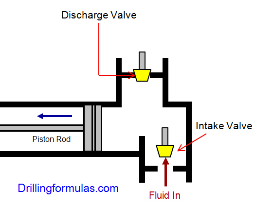
When the piston rod is moved forward, one of intake valves is lift to allow fluid to come in and one of the discharge valve is pushed up therefore the drilling mud is pumped out of the pump (Figure 2).
On the other hand, when the piston rod is moved backward drilling fluid is still pumped. The other intake and discharge valve will be opened (Figure 3).
The triplex pumps have three cylinders with single acting. The pistons are moved back and pull in drilling mud through open intake valves. When the pistons are moved forward and the drilling fluid is pushed out through open discharge valves.
On the contrary when the piston rods are moved backward, the intake valve are opened allowing drilling fluid coming into the pump (Figure 6). This video below shows how a triplex mud pump works.
Because each pump has power rating limit as 1600 hp, this will limit capability of pump. It means that you cannot pump at high rate and high pressure over what the pump can do. Use of a small liner will increase discharge pressure however the flow rate is reduces. Conversely, if a bigger liner is used to deliver more flow rate, maximum pump pressure will decrease.
As you can see, you can have 7500 psi with 4.5” liner but the maximum flow rate is only 297 GPM. If the biggest size of liner (7.25”) is used, the pump pressure is only 3200 psi.
Finally, we hope that this article would give you more understanding about the general idea of drilling mud pumps. Please feel free to add more comments.
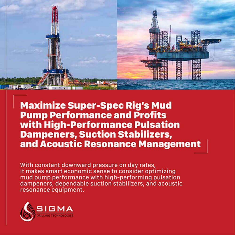
A well-placed suction stabilizer can also prevent pump chatter. Pump chatter occurs when energy is exchanged between the quick opening and closing of the reciprocating pump’s valves and the hammer effect from the centrifugal pump. Pump isolation with suction stabilizers is achieved when the charge pumps are isolated from reciprocating pumps and vice versa. The results are a smooth flow of pumped media devoid of agitating energies present in the pumped fluid.

Gear pumps are one of the most common types of positive displacement pumps. They provide a constant volume of fluid that passes between the teeth of two meshing gears and the casing. The rotating gears and separation of teeth create a suction that pulls fluid in through the inlet. The gears then trap the liquid and move it around the casing to the discharge or outlet. Each revolution creates consistency in the flow of fluid.
There are two main types of rotary gear pumps, internal and external. Both types use similar principles for pumping fluids. Two gears are inside a casing in a way that the teeth lock together. As a motor turns one of the gears the locking teeth turn the other. The difference in the two designs is that an external gear pump uses side-by-side gears (typically the same size), so when the motor turns one gear, the other rotates in the opposite direction. The internal gear pump design uses two different size gears. A motor turns the small gear, which is inside the larger gear, rotating it in the same direction.
DAE Pumps offers economical rotary gear pumps of both types in a variety of sizes. No other gear pumps can match the performance and durability of our pumps. Because of the close tolerance between the gears and casing, most gear pumps are highly susceptible to wear, but DAE Pumps gear pumps outperform all others. Our pumps process a wide range of viscosities and are ideal for handling fluids at high pressures and low flow rates. DAE Pumps rotary gear pumps are widely used in chemical installations to pump high viscosity fluids. They are one of the most common types of pumps for moving corrosive liquids and hydraulic fluid power applications.
DAE pumps gear pumps provide consistency in moving a variety of slurry materials and are suitable for several industries like paints, food processing, chemicals, oil & gas, and others. Our rotary gear pumps are available in duplex steel, cast steel, and cast iron, among other materials. Contact DAE Pumps to customize a pump to your specific needs.

When choosing a size and type of mud pump for your drilling project, there are several factors to consider. These would include not only cost and size of pump that best fits your drilling rig, but also the diameter, depth and hole conditions you are drilling through. I know that this sounds like a lot to consider, but if you are set up the right way before the job starts, you will thank me later.
Recommended practice is to maintain a minimum of 100 to 150 feet per minute of uphole velocity for drill cuttings. Larger diameter wells for irrigation, agriculture or municipalities may violate this rule, because it may not be economically feasible to pump this much mud for the job. Uphole velocity is determined by the flow rate of the mud system, diameter of the borehole and the diameter of the drill pipe. There are many tools, including handbooks, rule of thumb, slide rule calculators and now apps on your handheld device, to calculate velocity. It is always good to remember the time it takes to get the cuttings off the bottom of the well. If you are drilling at 200 feet, then a 100-foot-per-minute velocity means that it would take two minutes to get the cuttings out of the hole. This is always a good reminder of what you are drilling through and how long ago it was that you drilled it. Ground conditions and rock formations are ever changing as you go deeper. Wouldn’t it be nice if they all remained the same?
Centrifugal-style mud pumps are very popular in our industry due to their size and weight, as well as flow rate capacity for an affordable price. There are many models and brands out there, and most of them are very good value. How does a centrifugal mud pump work? The rotation of the impeller accelerates the fluid into the volute or diffuser chamber. The added energy from the acceleration increases the velocity and pressure of the fluid. These pumps are known to be very inefficient. This means that it takes more energy to increase the flow and pressure of the fluid when compared to a piston-style pump. However, you have a significant advantage in flow rates from a centrifugal pump versus a piston pump. If you are drilling deeper wells with heavier cuttings, you will be forced at some point to use a piston-style mud pump. They have much higher efficiencies in transferring the input energy into flow and pressure, therefore resulting in much higher pressure capabilities.
Piston-style mud pumps utilize a piston or plunger that travels back and forth in a chamber known as a cylinder. These pumps are also called “positive displacement” pumps because they literally push the fluid forward. This fluid builds up pressure and forces a spring-loaded valve to open and allow the fluid to escape into the discharge piping of the pump and then down the borehole. Since the expansion process is much smaller (almost insignificant) compared to a centrifugal pump, there is much lower energy loss. Plunger-style pumps can develop upwards of 15,000 psi for well treatments and hydraulic fracturing. Centrifugal pumps, in comparison, usually operate below 300 psi. If you are comparing most drilling pumps, centrifugal pumps operate from 60 to 125 psi and piston pumps operate around 150 to 300 psi. There are many exceptions and special applications for drilling, but these numbers should cover 80 percent of all equipment operating out there.
The restriction of putting a piston-style mud pump onto drilling rigs has always been the physical size and weight to provide adequate flow and pressure to your drilling fluid. Because of this, the industry needed a new solution to this age-old issue.
As the senior design engineer for Ingersoll-Rand’s Deephole Drilling Business Unit, I had the distinct pleasure of working with him and incorporating his Centerline Mud Pump into our drilling rig platforms.
In the late ’90s — and perhaps even earlier — Ingersoll-Rand had tried several times to develop a hydraulic-driven mud pump that would last an acceptable life- and duty-cycle for a well drilling contractor. With all of our resources and design wisdom, we were unable to solve this problem. Not only did Miller provide a solution, thus saving the size and weight of a typical gear-driven mud pump, he also provided a new offering — a mono-cylinder mud pump. This double-acting piston pump provided as much mud flow and pressure as a standard 5 X 6 duplex pump with incredible size and weight savings.
The true innovation was providing the well driller a solution for their mud pump requirements that was the right size and weight to integrate into both existing and new drilling rigs. Regardless of drill rig manufacturer and hydraulic system design, Centerline has provided a mud pump integration on hundreds of customer’s drilling rigs. Both mono-cylinder and duplex-cylinder pumps can fit nicely on the deck, across the frame or even be configured for under-deck mounting. This would not be possible with conventional mud pump designs.
The second generation design for the Centerline Mud Pump is expected later this year, and I believe it will be a true game changer for this industry. It also will open up the application to many other industries that require a heavier-duty cycle for a piston pump application.
Rene Moineau, a French engineer first invented and obtained several modified patents for a rotary type pump between 1930 and 1948. The pumps he developed were extensively used in the world war planes as superchargers. The first commercial PDM was introduced to the petroleum industry in the late 1950s. Their use increased in the late 1960s for the directional drilling application. However, their use has accelerated greatly with the present coiled tubing drilling.
The basic parts of a Moineau type motor involve a stator housing and a shaft enclosed in a casing. The center shaft has a wavy shaped cross section and each wave corresponds to a lobe. The housing which is contained in a casing accommodates the wavy shaped rotor, whose cross section is also wave shaped but the number of lobes is one more than in the shaft. When the shaft is inserted in the housing, the difference in their respective pitches creates a series of cavities. Drilling fluid pumped travels in a helical path between the shaft and the housing. In this process the drilling fluid displaces the shaft, forcing it to rotate clockwise as the mud continues to flow through the helical path.

Look Inside Positive Displacement Motor: A comprehensive and valuable book written by a team of outstanding experts in this tool and published through SigmaQuadrant publishing. The Positive Displacement Motors covers the full spectrum of topics in terms of analysis and design of the downhole mud motor that serves the workhorse of the downhole drilling system for several decades. This book presents functional, operational and technical aspects of positive displacement motor. It provides a platform ideal to seasoned engineer, experienced researcher and other professionals involved in the drilling operations as it offers real insight into this simple but complex machine. It highlights the background and development of this tool
In 1990s, the trend of introducing new technologies for drilling high angle and horizontal wells and sidetracks continued. The introduction of these technologies, where PDM is one of the main elements of multifunctional complex technical, gained progress in oil and gas industry. In the last 10 years, new generation motors with improved technical and operational characteristics were introduced. Dr. Rene Moineau, a French engineer first invented and obtained several modified patents for a rotary type pump between 1930 and 1948.
The pumps he developed were extensively used in the world war planes as superchargers. In fact, Archimedes invented a pump that consisted of a spiral shaft which when turned by hand lifted water from lake. Moineau basically developed further Archimedean screw pump idea. The first commercial PDM was introduced to the petroleum industry in the late 1950s. Their use increased in the late 1960s for the directional drilling application. However, their use has accelerated greatly with the present coiled tubing drilling.

Positive displacement pumps operate much differently than centrifugal pumps. Positive displacement pumps do not use impellers to pump liquids. Instead, they utilize rotating or reciprocating parts to push and transport the liquid into an enclosed volume. This design creates pressure, which drives the liquid to its destination, albeit at a much slower rate than what a centrifugal pump can accomplish. A positive displacement pump is ideal for higher viscosity liquids that are transported at low flow rates but a higher pressure.
Positive displacement pumps are categorized based on their mechanics, one category being rotary pumps and the other being reciprocating pumps. Reciprocating pumps work on the principle of a chamber expanding and contracting to change the pressure within the pump to draw fluids in, and then direct it out the discharge. Rotary pumps operate by utilizing a rotating or moving chamber that traps fluid between grooves and moves it from the suction to the discharge side of the pump.

Pumps are categorised into one of three main families; rotary positive displacement, reciprocating positive displacement, and centrifugal. Which pump technology is chosen for an application depends on a variety of reasons: the viscosity of the fluid, type of liquid being pumped, its abrasiveness, temperature and duty point required.
This article will provide an overview on what are rotary pumps and reciprocating positive displacement pumps, also known as PD. We"ll also dive into why they are important, when a certain type or design is most appropriate for an application, and finally, 8 Reasons to select a positive displacement pump for your application.
Positive displacement (PD) pumps are designed to ensure that any pumping action is forward (positive). Its internal design ensures and prevents fluid from recirculating back towards the pump inlet, or within its casing.
PD pumps can be of rotary or reciprocating positive displacement design. With differing internal parts, and designs to accommodate a variety of fluid characteristics.
There are more than 10 different types of positive displacement pumps. To explain their operation in simplistic form, PD pumps function by fluid being drawn into a chamber, or cavity by creating a vacuum.
Once the chamber is filled, the pump cycles causing the fluid present within the pump head to increase in pressure. This then causes it to be discharged via the discharge port into the pipework.
There are two families of PD pumps which are rotary and reciprocating positive displacement, they can be electrically, hydraulically or engine driven, and manufactured in almost any material to enable use across a variety of industries and applications.Rotary Positive Displacement Pumps
Rotary positive displacement pump types of function by a rotary action producing flow and pressure. Examples of these pump designs include. Vane, internal & external gear, lobe, peristaltic, screw and progressing cavity.Reciprocating Positive Displacement Pumps
As opposed to reciprocating positive displacement pumps. These pumps operate by converting an attached motors rotary forces into reciprocating motion. Examples of these designs include piston, plunger, and air operated diaphragm pumps (AODD).
As chambers within such pump designs contain a fixed volume - flow is proportional to speed. Calculations can be made with a high degree of accuracy of the flow produced per revolution. This enables estimates for the expected output or flow of the pump over a period of time.
These designs are unaffected by viscosity, meaning should the viscosity increase with temperature, equipment used with a variety of differing fluids, or the liquid being pumped, behave as a non-Newtonian fluid.
These types of units provide a constant pressure at pressures up to several bar higher than the required duty point. Compared to centrifugal pumps where a particular pressure and flow is only produced at a single duty point.
PD pumps operate at reduced speeds when compared to centrifugal pumps. This lower speed enables the handling of abrasive or solid laden liquids which would wear parts in a centrifugal pump.
This reduces wear and ensures that the liquid remains unaffected by the pumping motion, preserving its characteristics. This is especially important with liquids which are shear thickening, such as milks, creams, polymers, and gels.
All pumps have a minimum and maximum viscosity level, which is the viscosity limit they are engineered and designed to handle. If fluids are heated causing their viscosity to reduce to a level less than that designed limit, then pump will be unable to handle it and slip will occur.
Pump slip is where fluid recirculates within the pump head, causing a reduction in flow and pressure generated by the pump. This means fluid can continue to recirculate within the pump head and if left undetected can overheat causing the mechanical seal to fail.
Non-slip designs of positive displacement pumps are available. These designs ensure whatever a fluids viscosity, pump slip will not occur – like in this case study.
Flow is restricted due to its internal design on some pumps, meaning flow will be less than a centrifugal pump for low viscosity fluids. Some designs of positive displacement pumps are completely ruled out for certain applications. This is due to the flow not meeting the needed requirements for an intended application.
It"s common for two or more personnel being required for positive displacement pump maintenance, meaning more labour is required to service such designs of pump.
Such units are not usually cost effective for low viscosity fluids, or fluids which need transferring at low to medium flows where a centrifugal Pump could be used.
If left unrestrained, Positive displacement pumps will continue to build pressure in outlet pipework, until something gives relieving the pressure. This can be a valve, the pump itself or pipework, which is why quite often units are supplied complete with integrated relief valve.
Some designs of pumps such as AOD will stall or pause when outlet pressure reaches its maximum output. Other designs such as piston, need relief valves to reduce pressure or a pressure regulating valve to control the pressure to a set value.
A positive displacement pump curve differs to that of a centrifugal pump curve as the performance does not peak and then reduce as on a centrifugal pump performance curve - which shape resembles that of a bell.
In-fact positive displacement pump curves usually consist of several straight lines as in the image below, with a line per set pressure detailing the performance at that pressure against the speed the unit is operated at.
The curve differs to a centrifugal pump as it details the flow by pump speed. As opposed to a centrifugal pump where the speed is fixed, with the maximum flow and pressure available from the unit on the right of the performance chart.
Using positive displacement pumps ensures tankers can be stripped (completely emptied), with dry run designs ensuring pump damage does not occur. They are very effective at priming and ensure siphoning doesn’t occur where once the pump is stopped as in centrifugal designs.
Precise repeated delivery of fluids into a process means any pump selected must provide a set volume per revolution. This rules out centrifugal designs where it is possible for fluid to vary in flow or recirculate within a pump head.
Fluids used in these processes can vary by application but can include chemicals such as flocculants, coagulants in wastewater treatment, chemicals, flavourings, fuel, dyes, or paint. PD Pumps are known for their accuracy enabling dosing accuracies > 99% to be achieved.
To handle solids present within fluids, either suspended within the liquid or, in concentrated form and need reducing in size, or breaking apart or separating to be pumped.
This could be milks and creams that can become thicker if pumped at too high speed, or for preserving cell culture by using designs of pumps with a high solid passage or gentle pumping motion. Such designs ensure that the liquid transferred is consistent with each batch.
A centrifugal pump is sensitive to fluid viscosity. Risk comes from the fluid being more viscous than expected, changes with temperature or a variety of fluids used with the same pump. This could affect the output and duty performed by the pump being less than expected.
This is because as fluids become more viscous, they become harder to pump. The energy required for them to flow through pipework increases. Furthermore, as viscosity increases the efficiency of centrifugal pumps decreases leading to recirculation within the pump head.
For a variety of flow combinations. These could be high pressure with low flow requirements, or low flow and low pressure demands. PD pumps range in pressure generation capabilities from a few bar to thousands often in more compact designs.
There are many different internal parts to positive displacement pumps. There main parts are listed below grouped by pump designs, with common parts listed at the end.
The air side is the side of the diaphragm which expands and contracts being closest to the central air valve. The fluid side meets the fluid, filling and contracting with fluid as the pump cycles.
These are manufactured in a variety of plastics and metals depending on the fluid being pumped. They act as valves above and below each side of the diaphragms, below the top manifold and above the bottom manifold. They are responsible for maintaining pump efficiency and ensuring the pump can operate.
The balls located above and below the pump diaphragms are housed in cages. This to prevent the balls from damaging the tops of the manifolds and to stop them sticking to the top of the pump.
The air valve is located in the central manifold of the pump. Its purpose is to convert air flow and pressure into reciprocating movement. This drives a piston to compress one diaphragm then another.
Manifolds are located at the top and bottom of AOD Pumps. The suction manifold is designed to keep the pump diaphragms flooded with fluid. They act as a single delivery pipe on the pump discharge
This regulates how far the piston compresses the diaphragm via a dial at the rear of the pump. This is usually a setting between 0 – 100% of displacement.
This is driven via a gearbox and moves in a reciprocating motion compressing the diaphragm. When the diaphragm is compressed, fluid exits the pump head via the discharge valve. When the piston draws back the diaphragm expands drawing fluid into the pump head via the suction valve.
Responsible for sealing the pump head, ensuring that fluid drawn into the pump head and does not leak out. Also, that displacement is always via the discharge valves.
This is a rubber impeller which sits inside the pump casing. When inside the casing, several of the vanes are bent over forming a tight seal within the casing.
These maintain the liquid temperature within the pump head preventing solidification. This ensures the liquids viscosity remains within the handling capabilities of the pump.
The idler gear rotates within the rotary gear, driven by the pump shaft drawing fluid into the pump head. This builds pressure before its discharged via the outlet of the pump.
These are two interlocking gears mounted on separate shafts working in unison. They draw fluid around the outside of the pump casing. This fills the pump head before liquid builds in pressure and is discharged via the outlet.
These elements compress the hose, enabling pressures up to 8 bar to be generated. Their use extends hose life as well as using 30% less energy, enabling the pump to start from 1Hz. This allows for a greater flow range capability, and lower amounts of hosing lubricant.
There are often several plungers located within one pump head. In a triplex plunger pump, there are 3 plunger rods present. Flow and pressure are controlled by driving the plungers at different speeds and force.
All pumps have sets of valves ranging from non-return, to flow valves. Guided valves are used on some models and run within a sleeve during operation.
Driven by the output shaft of the gearbox, this rotates in a rotary manner within the stator pushing fluid that enters the inlet towards the outlet of the pump. They can be made in a variety of metals and hard chrome plated to suit a variety of liquids and applications.
The stator is held in place within the pump housing and made from a variety of rubbers such as EPDM, NBR and Viton. They can be assembled in a single piece with a rotor for pressures up to 24 bar. They can also be doubled up, enabling pumps to reach pressures of up to 48 bar. The stator forms much of the body in a progressing cavity pump.
Lobes rotate with the pump head generating the flow and pressure required. Rubber lobed pumps are usually self-priming, whereas metal lobed pumps need a flooded suction.
The piston drives back and forth within the rotor. This happens as the rotor rotates causing liquid to be drawn into the pump and expelled via the outlet.
A twin set of screws located side-by-side. These screws rotate within the pump casing causing fluid to be drawn towards the inlet. The fluid increases in pressure and is directed towards the outlet of the pump casing.
It is possible for screws to be mounted in pairs meaning up to 4 screws are in one pump. All screws mesh, ensuring fluid is directed from the inlet towards the outlet.
A driving screw is the main part responsible for producing flow and pressure within a triple screw pump. It intermeshes with two idler screws to increase fluid pressure with fluid then discharged from the casing. It"s driven either by the motor at full speed, or the output shaft of a gearbox at reduced speed for higher viscosity liquids or lower flow rates.
The rotor houses the various vanes within the pump. Vanes are slotted within rotor slots, and as it spins, vanes are pushed outwards against the pump casing.
Vanes sit within rotor slots. They are responsible for producing the flow and pressure within the pump head. Their material is changed depending on the fluid being pumped.
These are ports located on the pump to allow easy cleaning without disassembly of the pump. There is usually an inlet and outlet port that is used to automatically clean pumps. A mixture of chemicals and hot water are used for thorough cleaning between batches or between mixture changes.
Depending on the required fluid to be pumped, gearboxes are used to reduce the motor speed, usually operating at 2800rpm or 1400rpm at 50Hz to much lower speeds.
High viscosity fluids or pumps operating 24/7 usually need a low pump operating speed for pump longevity. This is to allow enough time for viscous fluids to flow into the pump head, or to reduce abrasion within the pump by reducing fluid velocity.
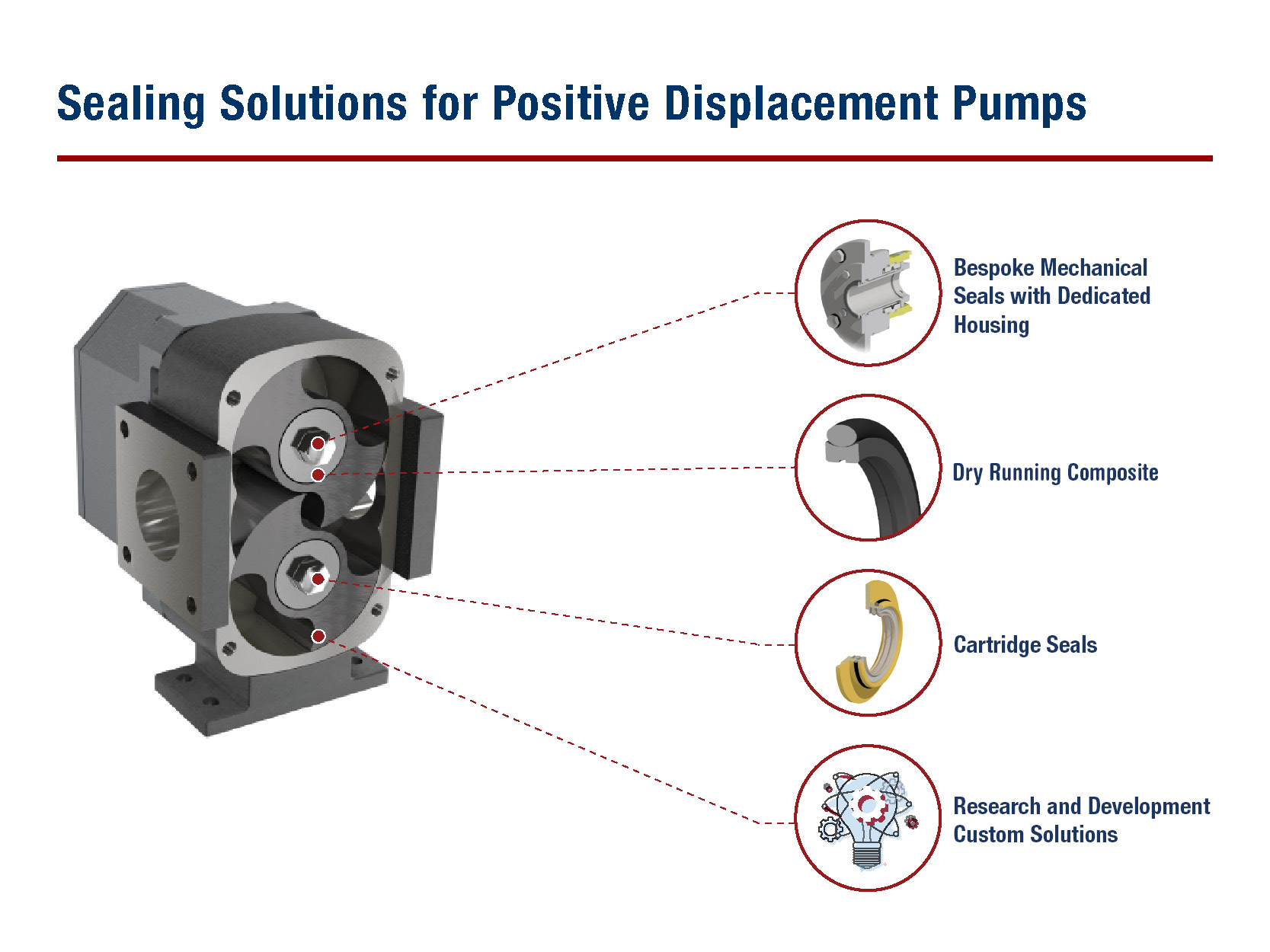
Pump heads are sealed using a mechanical seal or packed gland. A mechanical seal, seals around the shaft and pump casing. This seal consists of two faces and a spring. The faces and spring press against each other forming a seal that"s cooled by the pumped fluid. Dangerous or volatile chemicals may require a dual mechanical seal, or cartridge seal design.
O rings are used to seal around metal parts, such as within the pump casing, or around drainage ports. Metal itself is unable to create a seal without an elastomer, silicone, or plastic, acting as a barrier. O rings are placed into grooves where they are compressed between mating surfaces sealing the leak path.
Packed glands are a set of segmented rings. They are wound around the shaft and need the pumped liquid to lubricate the packing and keep it cool. If there is insufficient cooling the packing will burn. It is reliant on liquid leaking from the pump head for its correct function. The packing is tightened against the shaft using the packing press.
PD pumps continue to build pressure within the pump head and any connected pipework. If the pressure is not relieved in anyway, it will continue to build. If not addressed, it can lead to damage to the pump head and internal parts or failure in connected pipework.
They are also used in miniature designs of diaphragm pumps to ensure balls return to their original position. Mechanical seals need a spring to supply the pressure required to keep the stationary and rotating seal faces together.


 8613371530291