
pz11 mud pump gardner denver free sample

Mud Line ConnectionNote the extremely large nut and extended neck This is a 1003 mis-aligning union. It makes a more Stable connection when pipe is not lined up perfectly
MUD PUMP PERFORMANCE CHARTPUMP MODEL PZ-11 MAX I.H.P. 1600 MAX S.P.M. 115 STROKE LENGTH 11 MAX-P.S.I. G.P.R. 4 5000 1.80 4 5000 2.27 5 5000 2.80 5 5000 3.09 5 5000 3.39
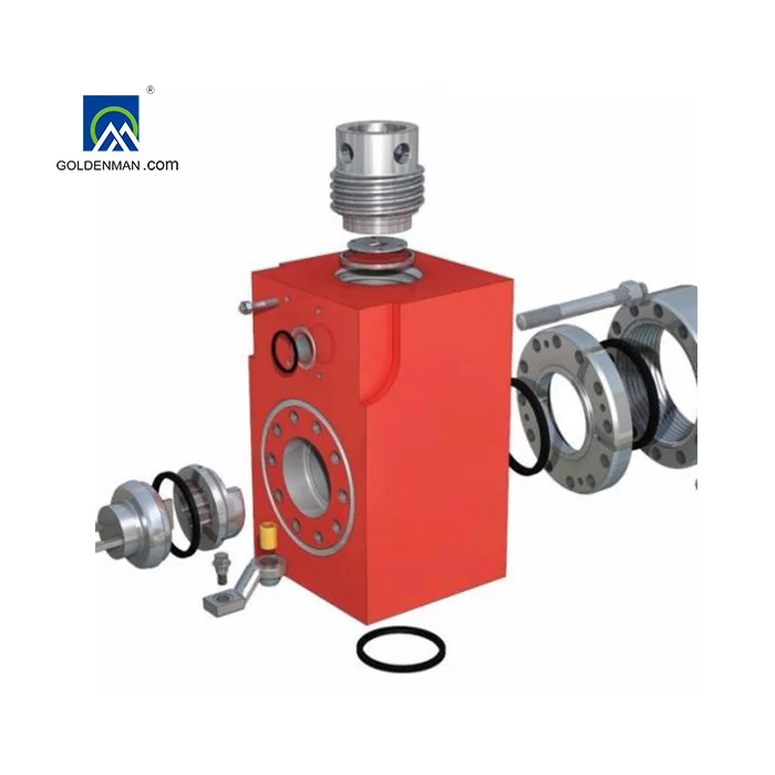
OEM GARDNER DENVERITEM NO. 1 2 3 4 5 5A 6 7 7A 8 9 9A 9B 9C 10 10A 11 12 13 14 15 16 17 18 19 20 21 22 23 24 PART NO. 1377YXX 2975SEE DETAILS FOR P.N.
LINER (REFER TO GUIDE TO ORDERING CHART FOR TYPE (Y) AND FOR SIZE (XX)) LINER SEAL WEARPLATE (8477-4 PART NUMBER SOUTHWEST MFG. FOR GARDNER DENVER OEM) GARDNER DENVER OEM 8477-53 WEARPLATE GASKET PISTON (REFER TO GUIDE TO ORDERING CHART FOR SIZE (XX) AND FOR TYPE (YY)) PISTON BUSHING (FROM 1-5/8 TO 1-1/2 STRAIGHT BORE) PISTON O-RING PISTON ROD (CLAMP TYPE WITH ELASTIC STOP NUT) PISTON ROD (SCREW TYPE WITH ELASTIC STOP NUT) PISTON ROD ELASTIC STOP NUT *FOR 2-PC. STUDDED PISTON ROD ASSEMBLY REFER TO GUIDE CHART FOR ORDERING ROD CLAMP (CONSIST OF 9A, 9B, 9C) HOSE (1/2 X 30 WITH 1/2 MALE X 3/8 MALE CONNECTIONS) SPRAY PIPE ROD CLAMP BOLT (5/8 X 5-1/2 GRADE 8 BOLT W/ LOCK NUT AND WASHER) PONY ROD (CLAMP TYPE) PONY ROD (SCREW TYPE) VALVE VALVE INSERT (IF REQUIRED) VALVE SPRING VALVE SEAT HYDRAULIC SEAT PULLER KIT COMPLETE (REFER TO TOOLS SECTION OF CATALOG FOR DETAILS) THREADED FLANGE SCREW GLAND PLUG (COMPLETE WITH VALVE GUIDE, SCREWS, AND BUSHING) HP VALVE COVER PLUG SEAL (P113U URETHANE AVAILABLE) VALVE GUIDE (COMPLETE WITH BUSHING #4700I) VALVE GUIDE BUSHING (4700IU URETHANE AVAILABLE) VALVE GUIDE SCREW VALVE COVER STUD (WITH SW PART# HHN1000-8 1-8 HEAVY HEX NUT) POWER END STUD (WITH SW PART# HHN1250-7 1-1/4 7 HEAVY HEX HUT) LINER RETAINER STUD (WITH SW PART# HHN1250-7 1-1/4 7 HEAVY HEX NUTS)
DESCRIPTION OEM DISCHARGE CROSS FOR PZ-11, PZ-10, PZ-9, PZ-8, PZ-7 GARDNER DENVER W/ 5" DISCHARGE LINE SPOOL FOR OEM PZ-11 DISCHARGE CROSS DISCHARGE STRAINER FOR OEM PZ-7 THRU PZ-11 PUMPS STUD FOR PZ-11 OEM DISCHARGE CROSS 5" 5000 PSI CONNECTION
TORQUE SPECIFICATIONS FOR OEM FLUID END ASSEMBLY GARDNER-DENVER PZ-11/PZ-10 5000 P.S.I. TORQUE TYPE (EXPRESSED IN FOOT-POUNDS) COPPERCOTE MOLY GREASE DRY (NOT RECOMMENDED)NO MORE FORCE THAN ONE MAN ON 3" WRENCH/CHEATER COMBINATION

MAINTAIN PUMP RELIABILITY AND PERFORMANCE WITHGENUINE GARDNER DENVERPARTS AND SUPPORT SERVICESGardner Denver and OPI genuine pump parts aremanufactured to original tolerances and designed foroptimum dependability. Design and material innovationsare the result of years of experience with hundredsof different pump applications. Reliability in materialsand quality assurance are incorporated in our genuinereplacement parts.Your authorized Gardner Denver and OPI distributoroffers all the backup you’ll need. A worldwide networkof authorized distributors provides the finest productsupport in the pump industry.Your local authorized distributor maintains a large inventoryof genuine parts and he is backed up for emergencyparts by direct access to the Gardner Denver MachineryInc. Master Distribution Center (MDC) in Memphis, Tennessee.Your authorized distributor can support your GardnerDenver and OPI pump needs with these services:1. Trained parts specialists to assist you in selectingthe correct replacement parts.2. Repair and maintenance kits designed with thenecessary parts to simplify servicing your pump.Authorized distributor service technicians are factory–trained and skilled in pump maintenance and repair.They are ready to respond and assist you by providingfast, expert maintenance and repair services.For the location of your local authorized Gardner Denver and OPI distributor refer to the yellow pages of yourphone directory or contact:Distribution Center:Factory:Gardner Denver Machinery Inc.Gardner Denver Machinery Inc.Master Distribution Center1800 Gardner Expressway5585 East Shelby Drive Quincy, IL 62301Memphis, TN 38141 Phone: (217) 222–5400Phone: (901) 542–6100 Fax: (217) 224–7814Fax: (901) 542–6159INSTRUCTIONS FOR ORDERING REPAIR PARTSWhen ordering parts, specify Pump MODEL andSERIAL NUMBER (see nameplate on unit). The SerialNumber is also stamped on top of the cylinder end of theframe (cradle area).All orders for Parts should be placed with the nearestauthorized distributor.Where NOT specified, quantity of parts required perpump or unit is one (1); where more than one is requiredper unit, quantity is indicated in parenthesis. SPECIFYEXACTLY THE NUMBER OF PARTS REQUIRED.DO NOT ORDER BY SETS OR GROUPS.To determine the Right Hand and Left Hand side of apump, stand at the power end and look toward the fluidend. Right Hand and Left Hand are indicated in parenthesisfollowing the part name, i.e. (RH) & (LH), whenappropriate.15–517 Page 1
Order by Part Number and Description. Reference Numbers are for your convenience only.D74881PISTON LUBRICATING PUMPRef.No. Name of Part Qty. Part No.PUMP ASSEMBLY, Includes All Parts Shown . . . . . . . . . . . . . . . . . . . . . . .CA1221 CASING . . . . . . . . . . . . . . . . . . . . . . . . . . . . . . . . . . . . . . . . . . . . . . . . . . . . . . . . 1 C1K2A12 PLUG–SqHd PIPE . . . . . . . . . . . . . . . . . . . . . . . . . . . . . . . . . . . . . . . . . . . . . . . 2 64AA63 COCK, Drain . . . . . . . . . . . . . . . . . . . . . . . . . . . . . . . . . . . . . . . . . . . . . . . . . . . . 1 90C314 IMPELLER ASSEMBLY, SHAFT & PIN . . . . . . . . . . . . . . . . . . . . . . . . . . . . . 1 C1K1A1A5 KEY . . . . . . . . . . . . . . . . . . . . . . . . . . . . . . . . . . . . . . . . . . . . . . . . . . . . . . . . . . . 1 35B46 SEAL . . . . . . . . . . . . . . . . . . . . . . . . . . . . . . . . . . . . . . . . . . . . . . . . . . . . . . . . . . 1 60BT118 GASKET . . . . . . . . . . . . . . . . . . . . . . . . . . . . . . . . . . . . . . . . . . . . . . . . . . . . . . . 1 25D2129 FRAME . . . . . . . . . . . . . . . . . . . . . . . . . . . . . . . . . . . . . . . . . . . . . . . . . . . . . . . . 1 C1H4A210 SCREW . . . . . . . . . . . . . . . . . . . . . . . . . . . . . . . . . . . . . . . . . . . . . . . . . . . . . . . . 8 75A13011 BEARING–BALL (Inner) Includes Retaining Ring . . . . . . . . . . . . . . . . . . . . 1 12AK312 BEARING–BALL (Outer) Includes Retaining Ring . . . . . . . . . . . . . . . . . . . 1 12AK315–517 Page 16
Order by Part Number and Description. Reference Numbers are for your convenience only.300PAH810(Ref. Drawing)OIL CIRCULATING PUMPRef.No. Name of Part Qty. Part No.OIL PUMP – COMPLETE . . . . . . . . . . . . . . . . . . . . . . . . . . . . . . . . . . . . . . . . . 1 201PAH1881 COVER . . . . . . . . . . . . . . . . . . . . . . . . . . . . . . . . . . . . . . . . . . . . . . . . . . . . . . . . . 1 20109872 WASHER . . . . . . . . . . . . . . . . . . . . . . . . . . . . . . . . . . . . . . . . . . . . . . . . . . . . . . . 1 20109923 BALL BEARING . . . . . . . . . . . . . . . . . . . . . . . . . . . . . . . . . . . . . . . . . . . . . . . . . 1 20109934 SHIM, Bearing . . . . . . . . . . . . . . . . . . . . . . . . . . . . . . . . . . . . . . . . . . . . . . . . . . . 1 20109945 ROTOR . . . . . . . . . . . . . . . . . . . . . . . . . . . . . . . . . . . . . . . . . . . . . . . . . . . . . . . . . 1 20109956 WASHER . . . . . . . . . . . . . . . . . . . . . . . . . . . . . . . . . . . . . . . . . . . . . . . . . . . . . . . 1 20109967 SEAL, Mechanical . . . . . . . . . . . . . . . . . . . . . . . . . . . . . . . . . . . . . . . . . . . . . . . . 1 21090038 O–RING . . . . . . . . . . . . . . . . . . . . . . . . . . . . . . . . . . . . . . . . . . . . . . . . . . . . . . . . 1 21090049 PLUG–HOUSING . . . . . . . . . . . . . . . . . . . . . . . . . . . . . . . . . . . . . . . . . . . . . . . . 1 201099710 HOUSING–BEARING . . . . . . . . . . . . . . . . . . . . . . . . . . . . . . . . . . . . . . . . . . . . 1 210900511 SEAL, Bearing Housing . . . . . . . . . . . . . . . . . . . . . . . . . . . . . . . . . . . . . . . . . . . 1 201099812 BEARING–ROLLER . . . . . . . . . . . . . . . . . . . . . . . . . . . . . . . . . . . . . . . . . . . . . . 1 2010999* VENT PLUG–SUCTION . . . . . . . . . . . . . . . . . . . . . . . . . . . . . . . . . . . . . . . . . . 1 2109000* VENT PLUG–DISCHARGE . . . . . . . . . . . . . . . . . . . . . . . . . . . . . . . . . . . . . . . . 1 2109001* WASHER, Vent Plug . . . . . . . . . . . . . . . . . . . . . . . . . . . . . . . . . . . . . . . . . . . . . . 2 2109002* Not shown.15–517 Page 17
Order by Part Number and Description. Reference Numbers are for your convenience only.OIL PUMP & PIPINGRef.No. Name of Part Qty. Part No.Ref.No. Name of Part Qty. Part No.15–517 Page 191 SCREEN–OIL . . . . . . . . . . . . . . . . . . . . . . . . . . . . . . . 1 3WAJ5112 ELBOW . . . . . . . . . . . . . . . . . . . . . . . . . . . . . . . . . . . . . 1 64C83 NIPPLE . . . . . . . . . . . . . . . . . . . . . . . . . . . . . . . . . . . . . 1 63U24X164 ELBOW . . . . . . . . . . . . . . . . . . . . . . . . . . . . . . . . . . . . . 1 64U49 PUMP–OIL** . . . . . . . . . . . . . . . . . . . . . . . . . . . . . . . . 1 201PAH18810 SCREW . . . . . . . . . . . . . . . . . . . . . . . . . . . . . . . . . . . . . 4 75A35N11 KEY . . . . . . . . . . . . . . . . . . . . . . . . . . . . . . . . . . . . . . . . 1 35D212 ADAPTOR, Oil Pump . . . . . . . . . . . . . . . . . . . . . . . . . 1 200PZL17013 PLATE, Oil Pump to Frame . . . . . . . . . . . . . . . . . . . . 1 PY52614 SCREW, Adaptor to Frame . . . . . . . . . . . . . . . . . . . . 4 655ED05D15 BUSHING–HUB, Gear . . . . . . . . . . . . . . . . . . . . . . . . 1 22F12SD16 GEAR–DRIVEN, Oil Pump . . . . . . . . . . . . . . . . . . . . 1 201PZL280* WIRE . . . . . . . . . . . . . . . . . . . . . . . . . . . . . . . . . . . . . . . 24” 97A29(Pump Discharge to Filter)20 ADAPTOR–HOSE . . . . . . . . . . . . . . . . . . . . . . . . . . . . 1 29Q1721 HYDRAULIC HOSE ASSEMBLY . . . . . . . . . . . . . . . 1 29R2122 TEE . . . . . . . . . . . . . . . . . . . . . . . . . . . . . . . . . . . . . . . . 1 64G723 VALVE–LIQUID RELIEF . . . . . . . . . . . . . . . . . . . . . . . 1 90Q6224 NIPPLE . . . . . . . . . . . . . . . . . . . . . . . . . . . . . . . . . . . . . 1 63U12X1625 UNION–STRAIGHT . . . . . . . . . . . . . . . . . . . . . . . . . . 1 64Z1026 NIPPLE . . . . . . . . . . . . . . . . . . . . . . . . . . . . . . . . . . . . . 1 63U12X3427 FILTER–OIL*** . . . . . . . . . . . . . . . . . . . . . . . . . . . . . . . 1 26C18(Filter to Crosshead Spray)28 NIPPLE . . . . . . . . . . . . . . . . . . . . . . . . . . . . . . . . . . . . . 1 63U12X1328A NIPPLE . . . . . . . . . . . . . . . . . . . . . . . . . . . . . . . . . . . . . 1 63U12X2229 ELBOW . . . . . . . . . . . . . . . . . . . . . . . . . . . . . . . . . . . . . 2 64C530 NIPPLE . . . . . . . . . . . . . . . . . . . . . . . . . . . . . . . . . . . . . 1 63U12X8031 TEE . . . . . . . . . . . . . . . . . . . . . . . . . . . . . . . . . . . . . . . . 1 64G732 REDUCER–PIPE . . . . . . . . . . . . . . . . . . . . . . . . . . . . . 1 64N2533 HYDRAULIC HOSE ASSEMBLY . . . . . . . . . . . . . . . 1 29Z2634 CLAMP, Hose . . . . . . . . . . . . . . . . . . . . . . . . . . . . . . . . 2 98H435 WASHER, Clamp . . . . . . . . . . . . . . . . . . . . . . . . . . . . 2 95B136 SCREW, Hose Clamp . . . . . . . . . . . . . . . . . . . . . . . . . 2 655EC03037 TEE . . . . . . . . . . . . . . . . . . . . . . . . . . . . . . . . . . . . . . . . 5 64G638 NIPPLE . . . . . . . . . . . . . . . . . . . . . . . . . . . . . . . . . . . . . 3 63F2139 ELBOW . . . . . . . . . . . . . . . . . . . . . . . . . . . . . . . . . . . . . 2 64C440 NIPPLE . . . . . . . . . . . . . . . . . . . . . . . . . . . . . . . . . . . . . 3 63N8X16041 BUSHING–PIPE . . . . . . . . . . . . . . . . . . . . . . . . . . . . . 6 64E2342 ELBOW . . . . . . . . . . . . . . . . . . . . . . . . . . . . . . . . . . . . . 6 64X143 NOZZLE . . . . . . . . . . . . . . . . . . . . . . . . . . . . . . . . . . . . 6 200998244 CLAMP . . . . . . . . . . . . . . . . . . . . . . . . . . . . . . . . . . . . . 2 200PZL65445 STUD . . . . . . . . . . . . . . . . . . . . . . . . . . . . . . . . . . . . . . . 2 79H146 NUT . . . . . . . . . . . . . . . . . . . . . . . . . . . . . . . . . . . . . . . . 2 50B547 LOCKNUT . . . . . . . . . . . . . . . . . . . . . . . . . . . . . . . . . . 2 50V44(Filter Tee to Trough)48 BUSHING–PIPE . . . . . . . . . . . . . . . . . . . . . . . . . . . . . 3 64E9549 NIPPLE . . . . . . . . . . . . . . . . . . . . . . . . . . . . . . . . . . . . . 1 63V8X1150 ADAPTOR–HOSE . . . . . . . . . . . . . . . . . . . . . . . . . . . . 2 29Q651 HYDRAULIC HOSE ASSEMBLY . . . . . . . . . . . . . . . 1 29Z8152 CLAMP, Hose to Frame . . . . . . . . . . . . . . . . . . . . . . . 5 PZ130153 SCREW, Clamp . . . . . . . . . . . . . . . . . . . . . . . . . . . . . . 1 655ED02054 ADAPTOR–HOSE . . . . . . . . . . . . . . . . . . . . . . . . . . . . 2 29Q1755 ELBOW . . . . . . . . . . . . . . . . . . . . . . . . . . . . . . . . . . . . . 1 64C5(Oil Trough to Main Bearing)56 TROUGH, Oil Feed . . . . . . . . . . . . . . . . . . . . . . . . . . . 1 201PZL12557 SCREW, Trough to Frame . . . . . . . . . . . . . . . . . . . . . 2 655EF04058 ADAPTOR–HOSE . . . . . . . . . . . . . . . . . . . . . . . . . . . . 2 29Q5459 HYDRAULIC HOSE ASSEMBLY . . . . . . . . . . . . . . . 2 29Z3560 NIPPLE, Trough to Jackshaft . . . . . . . . . . . . . . . . . . 2 63AJ6X13061 TROUGH, Jackshaft Bearing Oil . . . . . . . . . . . . . . . 2 202PZL12562 SCREW, Jackshaft Bearing Oil Trough . . . . . . . . . . 6 655EE03D* ELBOW, Hose to Bearing . . . . . . . . . . . . . . . . . . . . . . 2 64D4* WIRE . . . . . . . . . . . . . . . . . . . . . . . . . . . . . . . . . . . . . . . 96” 97A29* BUSHING–PIPE . . . . . . . . . . . . . . . . . . . . . . . . . . . . . 1 64E36* Not shown.** For Oil Pump and Component Parts See Page 17*** For Oil Filter and Component Parts See Page 25
Order by Part Number and Description. Reference Numbers are for your convenience only.PISTON LUBRICATING PIPING(General Service)Ref.No. Name of Part Qty. Part No.Ref.No. Name of Part Qty. Part No.15–517 Page 211 SCREEN–OIL . . . . . . . . . . . . . . . . . . . . . . . 1 2WAJ5112 NIPPLE . . . . . . . . . . . . . . . . . . . . . . . . . . . . 1 63H253 UNION–HAMMER, Wing . . . . . . . . . . . . . 1 64EB14 NIPPLE . . . . . . . . . . . . . . . . . . . . . . . . . . . . 1 63H255 VALVE . . . . . . . . . . . . . . . . . . . . . . . . . . . . . 1 90A366 NIPPLE . . . . . . . . . . . . . . . . . . . . . . . . . . . . 1 63H257 TEE . . . . . . . . . . . . . . . . . . . . . . . . . . . . . . . . 1 64G8G8 NIPPLE . . . . . . . . . . . . . . . . . . . . . . . . . . . . 1 63H259 VALVE . . . . . . . . . . . . . . . . . . . . . . . . . . . . . 1 90A3610 ADAPTOR–HOSE . . . . . . . . . . . . . . . . . . . 1 29Q911 HYDRAULIC HOSE ASSEMBLY . . . . . . . 1 29Z712 PUMP PISTON LUBRICATING,**Includes Reference Number 13 . . . . . . 1 CA12213 KEY . . . . . . . . . . . . . . . . . . . . . . . . . . . . . . . . 1 35B414 SCREW, Pump to Skid . . . . . . . . . . . . . . . 4 655ED04015 LOCKWASHER, Pump to Skid . . . . . . . . 4 95B316 WASHER, Pump to Skid . . . . . . . . . . . . . . 4 95A317 SHEAVE . . . . . . . . . . . . . . . . . . . . . . . . . . . . 1 73K1A3018 BUSHING–HUB . . . . . . . . . . . . . . . . . . . . . 1 22E16B19 BELT . . . . . . . . . . . . . . . . . . . . . . . . . . . . . . . 1 13C7920 AUXILIARY SHEAVE ASSEMBLY . . . . . 1 200PZL195A* SET SCREW, Sheave . . . . . . . . . . . . . . . . 2 76F30(Pump to Liner Group)21 ADAPTOR–HOSE . . . . . . . . . . . . . . . . . . . 1 29Q1022 HYDRAULIC HOSE ASSEMBLY . . . . . . . 1 200927023 ADAPTOR–HOSE . . . . . . . . . . . . . . . . . . . 1 29Q2724 REDUCER–PIPE . . . . . . . . . . . . . . . . . . . . 1 64N325 VALVE . . . . . . . . . . . . . . . . . . . . . . . . . . . . . 1 90A2526 ELBOW . . . . . . . . . . . . . . . . . . . . . . . . . . . . 1 64C527 NIPPLE . . . . . . . . . . . . . . . . . . . . . . . . . . . . 1 63G928 TEE . . . . . . . . . . . . . . . . . . . . . . . . . . . . . . . . 1 64P3929 CLAMP . . . . . . . . . . . . . . . . . . . . . . . . . . . . . 2 98H530 WASHER . . . . . . . . . . . . . . . . . . . . . . . . . . . 2 95B331 SCREW . . . . . . . . . . . . . . . . . . . . . . . . . . . . 2 75A6832 NIPPLE . . . . . . . . . . . . . . . . . . . . . . . . . . . . 1 63N12X18433 TEE . . . . . . . . . . . . . . . . . . . . . . . . . . . . . . . . 1 64P3934 NIPPLE . . . . . . . . . . . . . . . . . . . . . . . . . . . . 1 63N12X18435 TEE . . . . . . . . . . . . . . . . . . . . . . . . . . . . . . . . 1 64P3936 PLUG . . . . . . . . . . . . . . . . . . . . . . . . . . . . . . 1 64A537 HYDRAULIC HOSE ASSEMBLY . . . . . . . 3 29R3238 ADAPTOR–HOSE . . . . . . . . . . . . . . . . . . . 3 29Q8339 COUPLING–PIPE . . . . . . . . . . . . . . . . . . . 3 64BK340 BAFFLE . . . . . . . . . . . . . . . . . . . . . . . . . . . . 3 200PZL84041 NUT–ACORN . . . . . . . . . . . . . . . . . . . . . . . 6 50Q30(Frame to Lube Oil Tank Group)42 NIPPLE . . . . . . . . . . . . . . . . . . . . . . . . . . . . 1 63L2843 ELBOW . . . . . . . . . . . . . . . . . . . . . . . . . . . . 1 64C944 TANK–LUBE OIL . . . . . . . . . . . . . . . . . . . . 1 200PZL25045 PLUG . . . . . . . . . . . . . . . . . . . . . . . . . . . . . . 2 64A746 SCREW, Lube Tank to Skid . . . . . . . . . . . 4 655EE04047 WASHER . . . . . . . . . . . . . . . . . . . . . . . . . . . 4 95A548 PLUG . . . . . . . . . . . . . . . . . . . . . . . . . . . . . . 1 64A649 COVER–LUBE OIL TANK . . . . . . . . . . . . . 1 201265550 NUT–WING . . . . . . . . . . . . . . . . . . . . . . . . . 2 50H1* NIPPLE . . . . . . . . . . . . . . . . . . . . . . . . . . . . 1 63AJ32X60* Not shown.** For Piston Lubricating Pump and Components Parts See Page 16.
Order by Part Number and Description. Reference Numbers are for your convenience only.PISTON LUBRICATING PIPING(High Pressure Service)Ref.No. Name of Part Qty. Part No.Ref.No. Name of Part Qty. Part No.15–517 Page 231 SCREEN–OIL . . . . . . . . . . . . . . . . . . . . . . . . . . . . . . . 1 2WAJ5112 NIPPLE . . . . . . . . . . . . . . . . . . . . . . . . . . . . . . . . . . . . . 1 63H253 UNION–HAMMER, Wing . . . . . . . . . . . . . . . . . . . . . . 1 64EB14 NIPPLE . . . . . . . . . . . . . . . . . . . . . . . . . . . . . . . . . . . . . 1 63H255 VALVE . . . . . . . . . . . . . . . . . . . . . . . . . . . . . . . . . . . . . . 1 90A366 NIPPLE . . . . . . . . . . . . . . . . . . . . . . . . . . . . . . . . . . . . . 1 63H257 TEE . . . . . . . . . . . . . . . . . . . . . . . . . . . . . . . . . . . . . . . . 1 64G8G8 NIPPLE . . . . . . . . . . . . . . . . . . . . . . . . . . . . . . . . . . . . . 1 63H259 VALVE . . . . . . . . . . . . . . . . . . . . . . . . . . . . . . . . . . . . . . 1 90A3610 ADAPTOR–HOSE . . . . . . . . . . . . . . . . . . . . . . . . . . . . 1 29Q911 HYDRAULIC HOSE ASSEMBLY . . . . . . . . . . . . . . . 1 29Z712 PUMP PISTON LUBRICATING,** IncludesReference Number 13 . . . . . . . . . . . . . . . . . . . . . . 1 CA12213 KEY . . . . . . . . . . . . . . . . . . . . . . . . . . . . . . . . . . . . . . . . 1 35B414 SCREW, Pump to Skid . . . . . . . . . . . . . . . . . . . . . . . . 4 655ED04015 LOCKWASHER, Pump to Skid . . . . . . . . . . . . . . . . . 4 95B316 WASHER, Pump to Skid . . . . . . . . . . . . . . . . . . . . . . 4 95A317 SHEAVE . . . . . . . . . . . . . . . . . . . . . . . . . . . . . . . . . . . . 1 73K1A3018 BUSHING–HUB . . . . . . . . . . . . . . . . . . . . . . . . . . . . . . 1 22E16B19 BELT . . . . . . . . . . . . . . . . . . . . . . . . . . . . . . . . . . . . . . . 1 13C7920 AUXILIARY SHEAVE ASSEMBLY . . . . . . . . . . . . . . 1 200PZL195A* SET SCREW, Sheave . . . . . . . . . . . . . . . . . . . . . . . . 2 76F30(Pump to Liner Group)21 ADAPTOR–HOSE . . . . . . . . . . . . . . . . . . . . . . . . . . . . 1 29Q1022 HYDRAULIC HOSE ASSEMBLY . . . . . . . . . . . . . . . 1 200927023 ADAPTOR–HOSE . . . . . . . . . . . . . . . . . . . . . . . . . . . . 1 29Q2724 REDUCER–PIPE . . . . . . . . . . . . . . . . . . . . . . . . . . . . . 1 64N325 VALVE . . . . . . . . . . . . . . . . . . . . . . . . . . . . . . . . . . . . . . 1 90A2526 ELBOW . . . . . . . . . . . . . . . . . . . . . . . . . . . . . . . . . . . . . 1 64C527 NIPPLE . . . . . . . . . . . . . . . . . . . . . . . . . . . . . . . . . . . . . 1 63N12X20028 TEE–PIPE . . . . . . . . . . . . . . . . . . . . . . . . . . . . . . . . . . 1 64P3929 NIPPLE . . . . . . . . . . . . . . . . . . . . . . . . . . . . . . . . . . . . . 1 63N12X19030 TEE–PIPE . . . . . . . . . . . . . . . . . . . . . . . . . . . . . . . . . . 1 64P3931 NIPPLE . . . . . . . . . . . . . . . . . . . . . . . . . . . . . . . . . . . . . 1 63N12X20032 NIPPLE . . . . . . . . . . . . . . . . . . . . . . . . . . . . . . . . . . . . . 1 63G1933 TEE . . . . . . . . . . . . . . . . . . . . . . . . . . . . . . . . . . . . . . . . 1 64P3934 CAP–PIPE . . . . . . . . . . . . . . . . . . . . . . . . . . . . . . . . . . 1 64AD535 ADAPTOR–HOSE . . . . . . . . . . . . . . . . . . . . . . . . . . . . 3 29Q636 HYDRAULIC HOSE ASSEMBLY . . . . . . . . . . . . . . . 3 29R2937 ELBOW . . . . . . . . . . . . . . . . . . . . . . . . . . . . . . . . . . . . . 3 64C438 NIPPLE . . . . . . . . . . . . . . . . . . . . . . . . . . . . . . . . . . . . . 3 63F639 ELBOW . . . . . . . . . . . . . . . . . . . . . . . . . . . . . . . . . . . . . 3 64C440 NIPPLE . . . . . . . . . . . . . . . . . . . . . . . . . . . . . . . . . . . . . 3 63F3341 BRACKET . . . . . . . . . . . . . . . . . . . . . . . . . . . . . . . . . . . 3 300PZL017(Frame to Lube Oil Tank Group)42 NIPPLE . . . . . . . . . . . . . . . . . . . . . . . . . . . . . . . . . . . . . 1 63L2843 ELBOW . . . . . . . . . . . . . . . . . . . . . . . . . . . . . . . . . . . . . 1 64C944 TANK–LUBE OIL . . . . . . . . . . . . . . . . . . . . . . . . . . . . . 1 200PZL25045 PLUG . . . . . . . . . . . . . . . . . . . . . . . . . . . . . . . . . . . . . . . 2 64A746 SCREW, Lube Tank to Skid . . . . . . . . . . . . . . . . . . . . 4 655EE04047 WASHER . . . . . . . . . . . . . . . . . . . . . . . . . . . . . . . . . . . 4 95A548 PLUG . . . . . . . . . . . . . . . . . . . . . . . . . . . . . . . . . . . . . . . 1 64A649 COVER–LUBE OIL TANK . . . . . . . . . . . . . . . . . . . . . 1 201265550 NUT–WING . . . . . . . . . . . . . . . . . . . . . . . . . . . . . . . . . 2 50H151 FITTING–TUBE . . . . . . . . . . . . . . . . . . . . . . . . . . . . . . 3 86M1852 TUBE–FORMED . . . . . . . . . . . . . . . . . . . . . . . . . . . . . 3 300PZL85753 CAP–BAFFLE . . . . . . . . . . . . . . . . . . . . . . . . . . . . . . . 3 300PZL23754 RING–WATER DISTRIBUTION . . . . . . . . . . . . . . . . 3 300PZL46155 U–BOLT . . . . . . . . . . . . . . . . . . . . . . . . . . . . . . . . . . . . 6 12368456 LOCKWASHER . . . . . . . . . . . . . . . . . . . . . . . . . . . . . . 4 95B357 NUT . . . . . . . . . . . . . . . . . . . . . . . . . . . . . . . . . . . . . . . . 4 50AQ358 SCREW . . . . . . . . . . . . . . . . . . . . . . . . . . . . . . . . . . . . . 6 655ED04059 LOCKWASHER . . . . . . . . . . . . . . . . . . . . . . . . . . . . . . 6 95B360 BRACKET–WASH PIPE . . . . . . . . . . . . . . . . . . . . . . . 2 301PZL01761 SCREW–FLANGE HEAD . . . . . . . . . . . . . . . . . . . . . 6 75LM150* NIPPLE . . . . . . . . . . . . . . . . . . . . . . . . . . . . . . . . . . . . 1 63AJ32X60* Not shown.** For Piston Lubricating Pump and Components Parts See Page 16.
Order by Part Number and Description. Reference Numbers are for your convenience only.VALVE SEAT PULLER(OPTIONAL EQUIPMENT)Center FullRef. Guided OpeningNo. Name of Part Qty. Part No. Part No.1 HEAD (Not Included with 100E12 Puller) . . . . . . . . . . . . . . 1 100E13 ** 300PZL219VALVE SEAT PULLER ASSEMBLY, Includes ReferenceNumbers 2 thru 11 . . . . . . . . . . . . . . . . . . . . . . . . . . . . . . . 1 100E12 100E122 HYDRAULIC JACK . . . . . . . . . . . . . . . . . . . . . . . . . . . . . . . . . 1 2116728 21167283 CENTER STEM . . . . . . . . . . . . . . . . . . . . . . . . . . . . . . . . . . . . 1 2117314 21173144 CENTER STEM NUT . . . . . . . . . . . . . . . . . . . . . . . . . . . . . . . 1 2117315 21173155 PULLER H BAR BASE . . . . . . . . . . . . . . . . . . . . . . . . . . . . . . 1 2116727 21167276 CENTER BUSHING . . . . . . . . . . . . . . . . . . . . . . . . . . . . . . . . 1 2117316 2117316* CENTER BUSHING . . . . . . . . . . . . . . . . . . . . . . . . . . . . . . . . 1 2117317 21173177 HYDRAULIC HOSE . . . . . . . . . . . . . . . . . . . . . . . . . . . . . . . . . 1 2117318 21173188 HYDRAULIC PUMP . . . . . . . . . . . . . . . . . . . . . . . . . . . . . . . . 1 2117319 21173199 GAUGE ADAPTOR . . . . . . . . . . . . . . . . . . . . . . . . . . . . . . . . . 1 2117320 211732010 GAUGE COUPLER . . . . . . . . . . . . . . . . . . . . . . . . . . . . . . . . . 1 2117321 2117321* GAUGE COUPLER . . . . . . . . . . . . . . . . . . . . . . . . . . . . . . . . . 1 2117322 211732211 GAUGE 170 TON . . . . . . . . . . . . . . . . . . . . . . . . . . . . . . . . . . 1 2117323 2117323* CARRYING CASE . . . . . . . . . . . . . . . . . . . . . . . . . . . . . . . . . . 1 2117055 2117055* Not shown.** Shown on Drawing.15–517 Page 26
GARDNER DENVER UNIT RECORDThe following unit identification plate is provided as a convenience to you, our valued GardnerDenver customer. Please take the time to copy all the information from the actual nameplate ofyour unit. The model number, date manufactured and serial number will be required whencontacting the company or your distributor for information or replacement parts.200OPA496(Ref. Drawing)
A wide variety of gardner denver pz 11 mud pump options are available to you, such as 1 year, not available.You can also choose from new, gardner denver pz 11 mud pump,As well as from energy & mining, construction works gardner denver pz 11 mud pump.And whether gardner denver pz 11 mud pump is unavailable, {2}, or {3}.

We export-orientated mud pump parts, including liners, pistons, piston inserts, valve inserts, oil seals, rod packing, fluid ends etc.. All of them meet or exceed DIN and API standards and have been exported to U.K., Germany, USA, Canada, Pakistan, Middle East, and so on.

Gardner Denver and OPI genuine pump parts are manufactured to original tolerances and designed for optimum dependability. Design and material innovations are the result of years of experience with hundreds of different pump applications. Reliability in materials and quality assurance are incorporated in our genuine replacement parts. Your authorized Gardner Denver and OPI distributor offers all the backup you’ll need. A worldwide network of authorized distributors provides the finest product support in the pump industry. Your local authorized distributor maintains a large in-
ventory of genuine parts and he is backed up for emergency parts by direct access to the Gardner Denver Machinery Inc. Master Distribution Center (MDC) in Memphis, Tennessee. Your authorized distributor can support your Gardner Denver and OPI pump needs with trained parts specialists to assist you in selecting the correct replacement parts. Authorized distributor service technicians are factory– trained and skilled in pump maintenance and repair. They are ready to respond and assist you by providing fast, expert maintenance and repair services.
For the location of your local authorized Gardner Denver and OPI distributor refer to the yellow pages of your phone directory or contact: Distribution Center: Gardner Denver Machinery Inc. Master Distribution Center 5585 East Shelby Drive Memphis, TN 38141 Phone: (901) 542–6100 Fax: (901) 542–6159
INSTRUCTIONS FOR ORDERING REPAIR PARTS When ordering parts, specify Pump MODEL and SERIAL NUMBER (see nameplate on unit). The Serial Number is also stamped on top of the cylinder end of the frame (cradle area). All orders for Parts should be placed with the nearest authorized distributor. Where NOT specified, quantity of parts required per pump or unit is one (1); where more than one is required
per unit, quantity is indicated in parenthesis. SPECIFY EXACTLY THE NUMBER OF PARTS REQUIRED. DO NOT ORDER BY SETS OR GROUPS. To determine the Right Hand and Left Hand side of a pump, stand at the power end. Right Hand and Left Hand are indicated in parenthesis following the part name, i.e. (RH) & (LH).
FOREWORD Gardner Denver and OPI pumps are the result of advanced engineering and skilled manufacturing. To be assured of receiving maximum service from this machine the owner must exercise care in its operation and maintenance. This book is written to give the operator and maintenance department essential information for day–to–day operation, maintenance and adjustment. Careful adherence to these instructions will result in economical operation and minimum downtime.
TABLE OF CONTENTS Maintain Pump Reliability and Performance . . . . . . . . . . . . . . . . . . . . . . . . . . . . . . . . . . . . . . . . . . . . . . . . . . . . . . . . . . . . i Instructions For Ordering Repair Parts . . . . . . . . . . . . . . . . . . . . . . . . . . . . . . . . . . . . . . . . . . . . . . . . . . . . . . . . . . . . . . . . i Foreword . . . . . . . . . . . . . . . . . . . . . . . . . . . . . . . . . . . . . . . . . . . . . . . . . . . . . . . . . . . . . . . . . . . . . . . . . . . . . . . . . . . . . . . . . ii Index . . . . . . . . . . . . . . . . . . . . . . . . . . . . . . . . . . . . . . . . . . . . . . . . . . . . . . . . . . . . . . . . . . . . . . . . . . . . . . . . . . . . . . . . . . . . iv SECTION 1, Danger Notices . . . . . . . . . . . . . . . . . . . . . . . . . . . . . . . . . . . . . . . . . . . . . . . . . . . . . . . . . . . . . . . . . . . . . . . . 1 SECTION 2, Installation & Operating Instructions . . . . . . . . . . . . . . . . . . . . . . . . . . . . . . . . . . . . . . . . . . . . . . . . . . . . . . 7 SECTION 3, Routine Maintenance & Service Instructions . . . . . . . . . . . . . . . . . . . . . . . . . . . . . . . . . . . . . . . . . . . . . 15 SECTION 4, Dimensions & Running Clearances . . . . . . . . . . . . . . . . . . . . . . . . . . . . . . . . . . . . . . . . . . . . . . . . . . . . . 30
PZ Pump Outline . . . . . . . . . . . . . . . . . . . . . . . . . . . . . . . . . . . . . . . . . . . . . . . . . . . . . . . . . . . . . . . . . . 33
Pump, Lube Oil . . . . . . . . . . . . . . . . . . . . . . . . . . . . . . 17 Push Rods . . . . . . . . . . . . . . . . . . . . . . . . . . . . . . . . . . 23
SECTION 1 DANGER NOTICES personnel to refresh their memories in safe procedures and practices. Please read the following DANGER NOTICES before moving or operating the pump or any pump package unit equipment. Reciprocating pumps are machines capable of producing high fluid pressures and flow rates and are designed to be used with proper care and caution by trained, experienced operators. TO AVOID PERSONAL INJURY, DEATH AND/OR EQUIPMENT DAMAGE, READ AND THOROUGHLY UNDERSTAND THE FOLLOWING DANGER NOTICES PLUS THE ENTIRE OPERATING AND SERVICE MANUAL BEFORE ATTEMPTING TO MOVE OR OPERATE THE PUMP. Contact a Gardner Denver Machinery service representative if you are unable to comply with any of the danger notices or procedures described in these documents. Closely examine the data plate upon pump delivery to become thoroughly familiar with the operating limits for this pump model. The pump must never be operated at speeds, pressures or horsepower exceeding the maximum values shown on the data plate or at speeds below the minimum shown. Failure to observe the operating limits shown on the data plate could result in personal injury, death, and/or equipment damage and will void the warranty. Alterations to the pump, or application of the pump outside the data plate limits, must not be made without Gardner Denver Machinery written approval together with a new data plate, as dangerous operating conditions could result. THE DANGER NOTICE AND DATA PLATES PROVIDED ON THE EQUIPMENT MUST NOT BE REMOVED, PAINTED OVER, HIDDEN OR DEFACED. They must be replaced if they become damaged or unreadable. Provisions should be made to have the following written danger notices plus the pump operating and service manual readily available to operators and maintenance personnel. In addition, copies of all pump system accessory component (e.g. pressure relief valve, pulsation dampener, suction stabilizer, engine, electric motor, etc.) operating and service manuals should be readily available for operator and maintenance personnel use. Read and follow all the precautions and instructions contained in these manuals. If any of these documents are lost or become illegible they must be replaced immediately. The danger notices plus the operating and service manuals should be reread periodically by both operators and maintenance
Keep in mind that full operator attention and alertness are required when operating high pressure pumping equipment. Operators should not begin or continue operations when tired, distracted or under the influence of alcohol or any type of prescription or nonprescription drugs. The timely replacement of expendable parts and any other worn or damaged parts can prevent equipment damage and possible injury. The original parts used in Gardner Denver pumps are designed and tested to exacting standards to provide high quality performance and durability. Your best insurance in maintaining these characteristics is to use genuine Gardner Denver replacement parts. A broad range of danger notices are covered on these pages, however, they cannot substitute for training, experience and common sense in the safe operation of high pressure pumping equipment. HAMMER LUG FASTENERS
On pumps or pump package units equipped with hammer lug connectors and/or hammer lug valve covers the following precautions must be observed to avoid personal injury, death and/or equipment damage due to contact with the hammer, hammer bar, broken parts from the hammer, hammer bar or lugs or other objects propelled by hammer blows. When tightening or loosening hammer lug connectors and valve covers, operators or maintenance personnel should: S
Heavy equipment including pumps, pump package units and components should only be moved or lifted by trained, experienced operators, who are physically and mentally prepared to devote full attention and alertness to the moving and lifting operations. An operator should be fully aware of the use, capabilities, and condition of both the equipment being moved and the equipment being used to move it.
All pump covers must be securely fastened in proper position at all times when the pump is operating to avoid personal injury or death from moving parts. In addition, all moving parts on the entire pump package, including but not limited to engine or motors, drive shafts, belts, chains, pulleys, gears, etc., must be equipped with guards or covers, which must also be securely fastened in proper position at all times when the equipment is operating.
Failure to follow safe and proper pump, pump package or component lifting or moving procedures can lead to personal injury, death and/or equipment damage from shifting, falling or other unexpected or uncontrolled equipment movements. Make sure the hoist, lift truck, ropes, slings, spreader, or other lifting equipment you are using is in good condition and has a rated lifting capacity equal to or greater than the weight being lifted. Lifting devices must be checked frequently for condition and continued conformance to rated load capacity. They should then be tagged with the inspected capacity together with the date of inspection. Fully assembled pumps and pump package units are heavy and should only be moved using the specified lifting lugs or attachments. Many individual components have lifting eyes or lugs which must not be used to lift assemblies, as they are designed to bear the weight of the component only. Before lifting the individual component check to insure the lifting attachment is firmly secured to the component with undamaged, properly torqued fasteners, sound welds, or other secure attachments. Examine the lifting eyes, lugs, slots, holes or other projections to insure they are not cracked, otherwise damaged or badly worn. The repair of existing or addition of new welded lifting eyes, lugs or other projections should only be performed by experienced, qualified welders. Package units should be lifted with spreaders connected to the lifting attachments normally built into the package unit support skid. Packages too large to lift fully assembled should be separated into smaller loads.
For these smaller loads the lifting devices should be fastened to the lifting attachments normally built into the individual motor, engine, pump or transmission/ torque converter, or their separate support skids. When lifting subassembled components, for example a suction stabilizer attached to suction piping or a discharge pulsation dampener attached to a strainer cross and piping, use special lifting slings designed to safely support the combined weight of the components. If a crane or hoist is being used to lift large components or assemblies, one or more persons should assist the operator from the ground with guide lines attached to the equipment being moved to properly position it and prevent uncontrolled movement. When you start to lift a pump, package unit, subassemblies or individual components and you observe the equipment is tilting, or appears unbalanced, lower the equipment and adjust the lifting device to eliminate these improper lifting conditions before proceeding to move the equipment. It is poor practice and dangerous to allow the equipment to pass over or close to your body or limbs. Be prepared to move quickly out of danger if equipment starts to fall, slip or move unexpectedly toward you. PRESSURIZED PUMP SYSTEMS
Never place a shut–off valve or any other component between the pump discharge connection and the pressure relief valve. Make sure the pressure relief valve is installed so any pressurized relief discharge from the valve is directed away from possible contact with people or equipment. The relief valve must be set to relieve at a pressure equal to or below the maximum pressure values shown on the pump data plate. However, if a component is used in the discharge system with a lower rated pressure capability than that listed on the pump data plate, the pressure relief valve must be set to relieve at a pressure equal to or below the rated capability of the lowest rated component. Before starting the pump every time, check to insure:
Fluids under high pressure can possess sufficient energy to cause personal injury, death and/or equipment damage either through direct contact with escaping fluid streams or by contact with loose objects the pressurized fluid propels. Operating a pump against a blocked or restricted discharge line can produce excessive pressures in the entire discharge system, which can damage or burst discharge system components.
Never operate a pump without a properly sized pressure relief valve located in the flowing discharge line immediately adjacent to the pump discharge connection.
Check all fluid end discharge system components including pipe, connections, elbows, threads, fasteners, hoses, etc., at least once every six months to confirm their structural adequacy. With time, wear, corrosion and fatigue can reduce the strength of all components. Magnetic iron and steel components should be checked with magnetic particle or dye penetrant crack detection equipment. Nonmagnetic materials should be checked for cracks with dye penetrants. All metallic components should also be visually checked during these inspections for signs of corrosion. If a component shows evidence of cracking or loss of material due to corrosion it must be replaced with a new part. Continually monitor suction and discharge hose assemblies when the pump is operating for leakage, kinking, abrasion, corrosion or any other signs of wear or damage.
Worn or damaged hose assemblies should be replaced immediately. At least every six months examine hose assemblies internally for cut or bulged tube, obstructions and cleanliness. For segment style fittings, be sure that the hose butts up against the nipple shoulder, the band and retaining ring are properly set and tight and the segments are properly spaced. Check for proper gap between nut and socket or hex and socket. Nuts should swivel freely. Check the layline of the hose to be sure that the assembly is not twisted. Cap the ends of the hose with plastic covers to keep them clean until they are tested or reinstalled on the pump unit. Following this visual examination, the hose assembly should be hydrostatically tested, on test stands having adequate guards to protect the operator, per the hose manufacturer’s proof test procedure. Fluid end component inspections should be performed more frequently than every six months if pressures above 2500 psi are used in the discharge system or if corrosive, flammable or hot (over 110_ F) fluids are being pumped. Proper stuffing box packing selection is important for safe pump operation. Contact a Gardner Denver Machinery service representative for assistance in selecting the proper packing before beginning operation. Before starting the pump for the first time and periodically thereafter check the pump, suction and discharge system fastener torques versus the values listed in the Operating and Service Manual tables to insure proper tightness. Over and under torquing can damage threaded pipes, connections and fasteners, which may lead to component damage and/or failure. Replace all components found to be damaged or defective. On pumps equipped with stuffing boxes, the gland must be engaged by at least three (3) threads to hold the discharge pressure of the pump.
Do not attempt to service, repair, adjust the plunger packing or otherwise work on the pump while the unit is operating. Shut off the pump drive motor or engine and relieve the fluid pressure in the pump suction and discharge systems before any work or investigation is performed on the pump or pump systems. Block the crankshaft from turning and make certain that all pump drive motor or engine start switches or starter
controls are clearly tagged with warnings not to start the pump while repair work is in process. Whenever the pump is operating, continually monitor the entire suction, discharge and pump lubricating systems for leaks. Thoroughly investigate the cause for leakage and do not operate the pump until the cause of the leak has been corrected. Replace any parts which are found to be damaged or defective. When a gasketed joint is disassembled for any reason, discard the used gasket and replace it with a new, genuine Gardner Denver gasket before reassembling the joint. Due to the high working pressures contained by the fluid cylinder, discharge manifold and discharge piping, welding on these components is not recommended. If welding on the discharge system cannot be avoided, only experienced, qualified welders should be used. In addition, the welded part should be hydrostatically proof tested in the shop with water or hydraulic fluid to one and one half times maximum discharge system working pressure, with no observable fluid leakage, before the part is reinstalled in the pump system. In summary, high pressure fluid streams can possess sufficient energy to cause personal injury, death and/or equipment damage. These results can occur either through direct contact with the fluid stream or by contact with loose objects the fluid stream has propelled, if the pump system is improperly used, or if the fluid is misdirected, or allowed to escape from defective or improperly maintained equipment. FLAMMABLE, HOT, COLD OR CORROSIVE FLUID PUMPING
Extreme caution must be exercised by trained and experienced operators when flammable, hot, cold or corrosive fluids are being pumped, in order to avoid personal injury, death and/or equipment damage due to explosion, fire, burn, extreme cold or chemical attack. Never operate a pump which is pumping hydrocarbons or other flammable, hot, cold, or corrosive fluids when any part of the pump, suction system or discharge system is leaking. Stop the pump immediately if any leakage, other than a few drops per minute of packing weepage, is observed. Keep all flame, sparks, or hot objects away from any part of the pump, suction system, or discharge system. Shield the pump, suction
system and discharge system to prevent any flammable, hot, cold or corrosive fluid leakage from dripping or spraying on any components, flame, sparks, hot objects or people. Inspect the plungers, packing, gaskets and seals for fluid leakage frequently and replace all worn or leaking parts. Selection of the proper gaskets, seals and stuffing box packing is even more critical when flammable, hot, cold or corrosive fluids are being pumped than when other, inherently less dangerous fluids are used. Contact a Gardner Denver Machinery service representative for assistance in selecting the proper gaskets, seals and packing before beginning operation. Since some packing seepage into the cradle area is inevitable, the drain at the bottom of the cradle must be connected to a drain line which conducts the fluid leakage to a collection container located in a protected area. The entire drain system and container must be constructed of materials resistant to attack from the pumped fluid or from explosion or fire of the pumped fluid. Heavy duty cradle covers must be securely fastened in the proper position on the pump at all times when the pump is operating. If the pumped fluid releases harmful, explosive or flammable vapors the covers must be vented to conduct the fumes away from the pump unit to a nonhazardous area. Before beginning pumping operations or starting the pump power source (whether an engine or electric motor) check the atmosphere all around the pumping site for the presence of flammable or explosive vapors. Do not begin operation and stop ongoing operation if flammable or explosive vapors are detected. Hot surfaces, sparks, electric current or engine exhaust could ignite flammable or explosive vapors. Each engine used as a power source on pumping units where flammable or explosive vapors could form should be equipped with an air inlet shut–off. If flammable or explosive vapors are present in the pumping site atmosphere, an engine could continue to run on these vapors even after the engine fuel line is shut–off if an air inlet shut–off is not used. In addition, on pumping units used where flammable or explosive vapors could form, all electric motors used as power sources must be of explosion proof construction and all electrical components and wiring must meet the current National Electrical Code for explosive atmospheres. These precautions must be taken to avoid possible personal injury, death and/or equipment damage from explosion, fire or burns.
Extreme caution must be exercised if any type of wand, gun, nozzle or any other pressure and flow directing device is attached to the pump discharge system for use in jetting, blasting, cleaning, etc. This type of equipment must be used with utmost care by trained, experienced operators. High pressure fluid streams can either by direct contact or by propelling loose objects, cause serious personal injury or death to the operators and/or other persons. Pressure or flow directing devices often receive pressurized flow through flexible hoses, which can burst if they are kinked, cut, abraded or are otherwise worn, damaged or pressured above their rated capacity. Protect the hose and connections from damage by people, objects and vehicles. A broken, cut or otherwise burst hose can release pressurized fluid which may cause personal injury, death and/or equipment damage. High pressure fluid from hand held or hand directed pressure and flow directing devices may overpower an operator’s ability to control or direct the device, which could lead to personal injury, death and/or equipment damage. The operator must brace against the backward thrust of a hand held device. In addition, a safety harness or safety net must be used when working in an area where the operator could be injured in a fall. Stand to the side of any tubing or container being sprayed to avoid back spray and never operate a hand held device above shoulder level. Never direct the pressurized fluid stream at yourself or any other person, control valves, the pump, pump drive, suction or discharge systems. The pressurized stream can cause serious personal injury or death and can also change valve or control settings which could dangerously increase the delivery pressure to the pressure and flow directing device. When operating a pressure and flow directing device, use only equipment which automatically shuts off flow when an operator releases hand or foot pressure on the pressurized flow trigger control to prevent injury if the operator is overpowered or becomes disabled. Check to insure this automatic shut–off equipment is operating properly before every use and never circum-
Full operator attention and alertness are required when operating this equipment to avoid personal injury, death and/or equipment damage. The operators should take frequent rest breaks and cease operations when they become tired or distracted. Before the equipment is started, the work area must be inspected and properly prepared to avoid personal injury, death and/or damage to equipment. Make sure the work area is checked for hazardous fumes, has adequate ventilation for engine exhaust and sufficient drainage for released fluid. Check the work area for electrical equipment, connections, outlets, fixtures, or lines. If any are present they must be made water tight and the electrical power to these devices must be shut off to avoid electrical shocks from fluid contact. The work area should be clearly marked and roped off to keep unauthorized people and vehicles from entering. Remove all loose parts, tools and equipment from the work area before beginning operation. All pressure containing devices including wands, nozzles, guns, hoses, connections, etc., should be regularly checked for condition. These components should all be tagged with their tested pressure capabilities together with the date testing was performed. Always be aware of the pressure level in the system and never connect any equipment to the system which has a rated or tested pressure capability below the system operating pressure. The equipment must be shut down and the system pressure released before changing or disconnecting wands, nozzles, guns, hoses, connections or any other pressurized system components. All pressure containing devices including wands, nozzles, guns, connections, etc., plus all automatic shut–off, pressure and control equipment should be treated with care. Protect them from damage by people, objects and vehicles. Never lay them in dirt, mud, ice or other loose material which could plug the fluid opening or interfere with their operation. Never use the wand, nozzle, gun, etc. to pry loose material off items being cleaned. Before starting operation in a cold environment, check to make sure there is no ice in the fluid system and re-
After you have selected and purchased these components, follow the manufacturer’s instructions completely in their use. In summary, high pressure jetting, blasting and cleaning are inherently dangerous, as the pressures and flow rates needed to remove scale, clean, etc. are sufficient to cause personal injury, death and/or equipment damage resulting from, but not limited to, any of the conditions described in the above Danger Notices. STARTING A NEW PUMP – Pumps are shipped from the factory without oil in the crankcase. The hood should be removed and the power end examined and cleaned if necessary. The pump may have been in storage or in the yard for some time and as a consequence dirt may have entered the crankcase. Parts may have been robbed from the pump during storage and not replaced. All nuts and screws should be tightened. The jackshaft bearings have been supplied with grease at the factory and no grease should be added at this time, unless bearings have been disturbed. Be sure all valves in the discharge line are open. No valve should be installed between the pump and pressure relief valve in discharge line. To prevent excessive wear on the fluid pistons and packing when starting, remove a suction valve cover plate on each side of the fluid end and prime the pump. Pump should be started slowly, if possible, and should be operated for several hours with practically no discharge pressure. Check oil level as it may be necessary to add a small quantity of oil to compensate for that adhering to the walls of the crankcase and the moving parts. The pump may then gradually be brought up to full speed and full working pressure. Watch for undue heating or abnormal noise in the working parts. Check all joints in the suction line to be sure there are no air leaks.
Reference to Parts List covering the Model Pump being serviced is recommended in connection with this Instruction Manual. Repair Parts Lists with Sectional Views are available from any Gardner Denver Sales and Service Office. When ordering parts, always give size and serial number of pump. Always use genuine Gardner Denver parts. For efficient, factory–trained service, consult a Gardner Denver Service Specialist.
When working on any pump, be certain there is no fluid pressure on either suction or discharge side. Pressure on fluid end might move pump and cause damage or injury to personnel. It is recommended that all suction valve covers be removed to avoid fluid pressure building up against pistons or plungers.
LOCATION – Pump should be set level and solidly supported. The drive should be accurately aligned. Pump should be placed as close to the slush pit as possible to keep the suction line short and direct. Locate pump as low as possible to maintain a minimum suction lift to the centrifugal charging pump which is used because of the high speed of this type of mud pump. When the pump skid or master skid is to be bolted or welded to a platform or deck in the field, it is necessary that the following “Final Shimming Procedure” be followed. Final Shimming Procedure – After the pump skid or master skid has been bolted or welded to a stationary platform or deck, proceed as follows: a.
SUCTION LINE – Suction pipe or hose to centrifugal charging pump should be a minimum of 12 inches (304.8 mm) diameter and as short as possible. Always use eccentric reducers when reducing suction pipe size. Suction line should slope up toward the charging pump at uniform grade to prevent air pockets being formed. Suction line must be absolutely tight as any air leaking into the line will reduce the capacity of the pump and cause a hydraulic hammer or knock. If it is necessary to have bends in the suction line they should have long radius sweeps and be kept to a minimum in quantity. 10–40 PSI suction required.
Suction line should be supported near centrifugal charging pump to keep strain from breaking the casing at suction flange. At least one section of hose in the suction line is desirable to isolate pulsations or vibration. Total suction line should be as short as installation conditions permit. THIS IS IMPORTANT. A suction strainer is recommended for the suction line of every pump. It must be checked frequently and cleaned whenever necessary. A commercial strainer may be installed in suction line ahead of the pump. It is recommended that a 50 PSI (3.515 kg/cm2) gauge with a needle valve for protection be installed in the suction line at the discharge of the centrifugal charging pump. This gauge will indicate if pump is charging or if suction valves are not working properly. RELIEF VALVES – The pump should be protected from excess discharge pressure by a 3 inch (76.2 mm) relief valve. This valve should be installed in a vertical position in a tee mounted directly onto either end of discharge manifold or discharge cross.
If more than one pump is used, a pressure release valve should be furnished for each pump. A hand–operated pressure release valve should be installed in discharge line following the relief valve, with discharge line leading to mud tank. This valve is used to bleed air from discharge line in starting. It is also used to relieve pressure in starting more than one pump in parallel. SURGE CHAMBER – A surge chamber is essential. One MUST be used for protection to surface equipment and to reduce pulsations when pumping gaseous mud. A nitrogen–charged pressure–bag type surge chamber is recommended. The surge chamber must be kept properly charged, as instructed by the manufacturer.
the lower slide. This means better lubrication and quiet operation. Lube oil pumps are not automatic reversing. If PZ pumps are to be run in reverse direction, refer to “Lube Oil Pump”. Pumps are shipped from the factory without oil in the crankcase. The hood should be removed and the power end examined and cleaned if necessary. The pump may have been in storage or in the yard for some time, and as a consequence, dirt may have entered the crankcase. Drain all water accumulated in the bottom of the crankcase. Fill crankcase with oil of proper grade to the proper level. Quantity shown on lubrication data plate indicates the approximate oil requirements. All nuts and cap screws should be checked for tightness. It is recommended that the fluid end of the pump be primed to prevent excessive wear on the fluid pistons and liners when starting. PRIMING IS IMPORTANT! IT LUBRICATES THE PISTONS IN THE LINERS. Pump should be started slowly but not run below half of rated speed. Recheck oil level as it may be necessary to add a small quantity of oil to crankcase and the moving parts. The pump may then be gradually brought up to full speed and full working pressure. Check all joints in the suction line to be sure there are no air leaks. LUBRICATION – All power end working parts are lubricated by the oil in the crankcase. Check oil level frequently. Selection of oil is to be taken from the recommendations given in FIGURE 2 and on the pump data plate. Local conditions and practice may also influence the selection. Essential additives are foam and oxidation inhibitors. Oil is to be added as required to maintain oil level near the top of the oil level indicator on the side of the frame.
STARTING A NEW PUMP – It is recommended that the drive be arranged to turn the pump in the direction indicated by arrow shown on the sectional view in this book, on outline prints, and indicated on pump frame. This book provides for crosshead load to be carried on
Time between oil changes depends upon local and/or operating conditions. Under normal circumstances, if the crankcase is kept clean, it should not be necessary to change oil more than once in 1000 hours of operation. Many operators change oil after each well drilled. Oil should be changed if found to be dirty or contaminated with mud or water. This is especially important for the PZ pump, as the oil lubricated roller bearings will be damaged by contamination. An oil change is comparatively inexpensive, as the approximate crankcase capacities are shown in FIGURE 4.
An 80_ F (27_ C) crankcase oil temperature rise over ambient air temperature is typical for the pumps covered by this manual when operating at or near rated horsepower.
Some operating conditions and/or oil brands produce excessive oil foaming, even when the specified GL–5 oils containing antifoaming additives are used. Oil foaming can cause pump damage, as oil bubbles will not lubricate moving parts properly. If significant oil foaming occurs, contact Gardner Denver Marketing or Service, (217) 222–5400, for the current factory recommended defoamant to be added to the lubricating oil.
Oil is constantly circulated through a renewable element filter and then through a heat exchanger, when one is used, by means of a rotary pump driven from the main gear. Oil is discharged into an elevated oil feed trough, from which it is conducted to jackshaft and main bearings. Oil also flows from the trough to lubricate the connecting rod bearings.
In order to assure proper lubrication, the PZG, PZH & PZJ pumps should not be run under 10 RPM for more than a few minutes at a time without providing additional lubrication from an extra external oil pump. The PZK & PZL pumps should not be run under 40 RPM. The oils normally used in large mud pumps are quite viscous at lower temperatures. When starting cold, the pump should be started slowly and brought up to operating speed slowly. This practice will assure proper lubrication of all working parts before pump is fully loaded. OIL FILTER – A replaceable element oil filter is located inside the pump crankcase. Filter mounting flange is on the outside (FIGURE 5, page 10), making it possible to replace the element by removing end plate. Only the oil within the filter case will be spilled when element is withdrawn. Filter element should be replaced each time crankcase oil is changed or every 1000 hours of operation.
not otherwise drain due to small size of tubes, capillary attraction, and the horizontal position of the heat exchanger mounting. Water should not be admitted to the heat exchanger as long as oil temperatures do not exceed 160_ F(71.1_ C). A dial thermometer is standard equipment on all PZ pumps. Salt water can be used for cooling. Zinc anode plugs are provided for corrosion protection. These plugs are to be replaced when they have been corroded away. DIRECTION OF ROTATION – The PZ pump MUST be driven in the direction as shown by arrow on sectional view, outline drawing and on pump frame. The oil pump on PZG, PZH and PZJ models is a nonreversible pump. If the PZ pump must be run in reverse direction, see “Lube Oil Pump”, page 17.
Filter element is protected from excessive internal oil pressure by a relief valve between it and the oil pump. On units equipped with a heat exchanger, oil flows through the oil filter before going through the heat exchanger. HEAT EXCHANGER (Optional Equipment) – For Models PZG, PZH & PZJ a bronze heat exchanger can be provided to keep crankcase oil temperature at 160_ F (71.1_ C) by means of an automatic water control valve. This valve has a sensing probe in the crankcase oil, and it monitors water to the heat exchanger to maintain oil temperature within close limits. Water must be drained from the heat exchanger during freezing weather. Ruptured water tubes will admit water into the oil, with resulting damage to working parts of the pump. Cooling water can be drained from the heat exchanger by removing water connections and blowing compressed air into upper opening. Water will then flow from the lower opening. Air is necessary, as water will
Running pump in the prescribed direction will also result in proper lubrication and quiet operation as load on crosshead will be carried on the lower side. CROSSHEAD DRAINS – Model PZ pumps are equipped with two plugged drain openings below and in front of the crossheads. These openings are to drain any possible leakage from the oil stop head packings which collects in a small reservoir built into the frame. This area should be drained daily. It is recommended that these openings be piped together and a valve installed to simplify the daily draining. Failure to drain this area could result in drilling mud in the power end and possible premature failure. OPERATION – For normal drilling operat


 8613371530291