
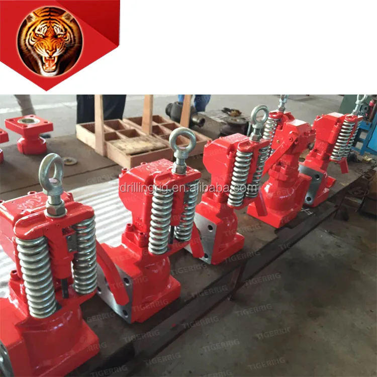
relief valve mud pump free sample

A wide variety of pressure relief valve for mud pump options are available to you, You can also choose from new, pressure relief valve for mud pump,As well as from energy & mining, construction works , and machinery repair shops. And whether pressure relief valve for mud pump is 1.5 years, 3 months, or {3}.

Relief valve mud pump is also called the centrifugal pump, a compressor, and a compressor. It has a series of pistons, this is done in the form of a centrifugal pump, with a compressor. It is usually used by hydraulic maintenance. The rotating pumps have different cuffs and suction cuffs.@@@@@
Relief valve mud pumps are specially designed for the rotation of the vehicle. There are many types of relief valve mud pumps, suitable for a rotating purpose, such as electric relief valve mud pumps. In the case of the different, pumps are suitable for a rotating process. They are suitable for rotating, there are various sizes and varieties of the pumps depending on the rotation pattern, but with a lesser water flow. On the other hand, there are various types of relief valve mud pumps that are specially designed for use in rotating processes. If the pump is suitable for a rotary motion, these pumps are suitable for a rotary process, and can be used on both sides of the vehicle. On Alibaba.com, there are various types of relief valve mud pumps, such as electric relief valve mud.

For 50 years, Giant Pumps has offered the most dependable positive displacement high-pressure triplex pumps available. Designed and built to the highest quality standards, customers count on Giant Pumps products to keep their equipment running. Every design detail of Giant Pumps products is optimized for long-life and reliable performance, making Giant Pumps the most trusted name in high-pressure pumps and systems.

In many liquid piping systems, it is vital that line pressure is maintained within relatively narrow limits. This is the function of the 108 Pressure Relief / Back Pressure Series of the OCV control valves. Installed in the main flow line, the standard Model 108-2 acts as a backpressure or pressure sustaining valve. In this configuration, the valve maintains a constant upstream pressure regardless of fluctuating downstream demand. When used in a bypass line, the same model will function as a relief valve, protecting the system against potentially damaging surges.
Protects system from over pressure by exhausting excess pressure. The valve may only have to operate intermittently to prevent pressure surges that might occur on pump start, pump stop, or sudden downstream valve closure.
Valve allows flow when inlet pressure is above the set-point thus preventing inlet pressure from falling too low. Prevents demand from “robbing” the source, or keeps pump “on its curve.”
RELIEF VALVE – Closed under normal operating pressures. Valve opens when pressure rises to the set point. Valve will close when system pressure drops below set point.
2.) Model 1330 Pressure Relief Pilot, a two-way, normally-closed pilot valve which senses upstream pressure under its diaphragm and balances it against an adjustable spring load. An increase in upstream pressure tends to make the pilot open.
3.) Model 126 Ejector, a simple “tee” fitting with a fixed orifice in its inlet port. It provides the proper pressure to the diaphragm chamber of the main valve depending on the position of the pressure relief pilot.
4.) Model 141-3 Flow Control Valve, a needle-type valve which provides adjustable, restricted flow in one direction, and free flow in the opposite direction. On the 108-2, the flow control valve is connected as a closing speed control.
5.) Model 159 Y-Strainer (standard on water service valves) or Model 123 Inline Strainer (standard on fuel service valves). The strainer protects the pilot system from solid contaminants in the line fluid.
6A / 6B.) Two Model 141-4 Ball Valves (standard on water service valves, optional on fuel service valves), useful for isolating the pilot system for maintenance or troubleshooting.
The Model 1330/2400 Pressure Sustaining Pilot controls the amount of pressure in the upper chamber of the Main valve(s). (Hence, the degree of opening or closing of the Main valve). The upstream pressure increases, the pilot begins to open, decreasing the amount of pressure in the upper chamber of the main valve allowing it to open a proportionate amount, in order to maintain a constant inlet pressure. As the upstream pressure decreases, the pilot begins to close, allowing the pressure in the upper chamber of the main valve to increase causing it to close. This is a constant modulating action compensating for any change in upstream pressure.
For the most comprehensive procedure in sizing Series 108 control valves, it is best to use our ValveMaster software or the guidelines shown here in conjunction with the Performance Charts in the Engineering Section of the OCV catalog.
Bypass pressure control valves are sized based on maximum flow and pressure drop across the valve. The maximum flow through the valve is the pump flow at the desired set point (from the pump curve) minus the minimum system flow. The pressure drop across the valve is the set point minus the pressure at the valve discharge (typically pump suction or storage tank head). Determine the valve’s operating Cv using the maximum flow and pressure drop from the formula:
Size is determined by the amount of flow required to lower the inlet pressure. This relief flow can be difficult to determine, so a general guideline is to use 60% of the rated pump flow. The 108 Series valve is capable of intermittent flows up to 45 ft. per second. Relief valve sizes are typically 50-60% of the mainline size.
Many surge relief, and some bypass pressure control valves are, by their application, subject to pressure differentials that may induce cavitation. When these conditions exist, it may be only on an intermittent basis, causing minimum concern for valve deterioration.
By combining various control pilots, multiple valve functions can be performed on a single Series 108 Pressure Relief Valve. To find the combination function valve, select the desired features and then the model number. This chart shows only a sample of those most often specified valves. Consult the factory for specific data on the model you selected.
Combination valves can often reduce or eliminate other equipment. Example: If the system requires a Back Pressure Valve and a Check Valve, the check feature can be added as a function of the Back Pressure, Model 108-3.
When valve inlet pressure requires the model 2400 High Pressure Relief pilot, an HP is added to the end of the model number. Example: Standard model 108-2 (inlet ranges from 5 – 300 psi) Model 108-2HP (outlet ranges 200-750 psi)
For maximum efficiency, the OCV control valve should be mounted in a piping system so that the valve bonnet (cover) is in the top position. Other positions are acceptable but may not allow the valve to function to its fullest and safest potential. In particular, please consult the factory before installing 8″ and larger valves, or any valves with a limit switch, in positions other than described. Space should be taken into consideration when mounting valves and their pilot systems.
Series Number – Valve size – Globe or Angle – Pressure Class – Screwed, Flanged, Grooved – Trim Material – Adjustment Range – Pilot Options – Special needs / or installation requirements.

From the raw water intake to the filtration plant to the finished waster distribution and storage system, GA Industries valves have been providing dependable service in large and small water systems. GA Industries pump control, check and relief valves mitigate damaging pressure surges and eliminate slam and bang that can result from the operation of water pumps.
Air trapped in water pipelines can reduce system efficiency and exacerbate pressure surges. Our wide range of automatic air valves ensures we have the right valve to maintain an air free system.
And when it’s necessary to isolate a pump, process or section of pipeline, you can depend on GA Industries butterfly valves for reliable flow shutoff.
What"s the best way to avoid trouble? Seek the path of least resistance. While this may not be the best advice for all situations, it is helpful for us to know that fluids follow this cliché with predictable behavior. Applying this knowledge to your pump/system can prevent expensive downtime when component failure is caused by unavoidable or unexpected high pressure spikes. How do you compensate for high pressure spikes? A simple, but very effective, way is to install a relief valve.
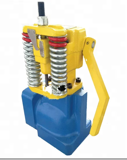
The relief valve (also called a bypass valve) is a mechanism used to control or limit pressure by allowing the fluid to flow into an auxiliary passage, away from the main flow path. The relief valve is designed or set to activate at a predetermined pressure. When this pressure setting is exceeded, the relief valve becomes the “path of least resistance” as the valve is forced open and a portion of the fluid is diverted through the auxiliary route. The diverted fluid is usually returned back to either the reservoir or the pump inlet. Generally, the relief valve is used as a safety precaution bysetting a limit for the maximum operating pressure of the system or pump, ready to operate should the system exceed its pressure limits. The relief valve and bypass path can be internal (an integral part of the pump) or external (installed as a component in the fluid path).
An internal bypass simply recirculates the fluid within the pump, returning the fluid from the outlet chamber to the inlet chamber. Cut-away views of a Series GJ and GB pump (see Fig. 1) show how discharge fluid fills the magnet cup. As the discharge pressure on the outlet side of the pump increases, so does the pressure within the magnet cup. When this pressure exceeds the force of the bypass spring holding down the poppet, it pushes the poppet off its "seat," allowing fluid to move through the auxiliary passage to the pump inlet. Bypass spring tension (and, consequently, bypass opening pressure) can be increased or decreased externally by adjusting the bypass screw (see Fig. 1).
This recirculation of fluid takes place in a small area (Fig. 1a) of the bypass. When the bypass remains open and the fluid is recirculated over a prolonged period, the energy of fluid movement and fluid friction will cause an increase in fluid temperature. Users should be aware that even when the fluid temperature in the system does not exceed recommended values, bypass conditions may create a sufficient temperature rise to cause significant swelling in PTFE-geared pumps. Fluid heating is a primary concern when the bypass is used to recirculate a large percentage of pumped fluid in small volume, closed-loop systems.
The external bypass is created by installing a relief valve in the system. Relief valves are available from several sources and typically operate on the same principle as explained previously: a poppet held in place with a spring is activated when the fluid pressure overcomes the force exerted by the spring. An external bypass is usually designed with the relief valve located close to the pump outlet and upstream of any other valves in the system. The diverted fluid should be directed back to the supply reservoir to avoid any possibility of fluid temperature problems as described previously. Figure 2 shows a possible bypass configuration.
Closed bypass This is when the relief valve is closed. In our pumps, this occurs when the adjusting screw is turned all the way in (clockwise), compressing the bypass spring all the way, and the pump experiences full-flow and pressure-producing capabilities.
Full-flow bypass pressure This is the fluid pressure when maximum flow is passing through the relief valve and bypass path. In our pumps, 100% of the bypass output is recirculated.
Relief valves should be “set” to open at a pressure above the operating pressure. This provides system safety. Care should be taken when determining the maximum system pressure. Use the component with the lowest pressure rating as a guide for establishing your limit. Don"t forget, this component could be the tubing!
In fluid handling applications, many markets have systems where high flow/low pressure is needed in one phase, followed by low flow/high pressure needs in the next phase. As always, the system and pump designer must conserve power, prevent temperature increases, and provide reliable solutions immediately (or sooner). The bypass valve offers a means of solving system problems and providing safety in a practical manner, without breaking tight budgets. So consider the path of least resistance on the way to your next solution. You may find relief!
Created specifically for drilling equipment inspectors and others in the oil and gas industry, the Oil Rig Mud Pump Inspection app allows you to easily document the status and safety of your oil rigs using just a mobile device. Quickly resolve any damage or needed maintenance with photos and GPS locations and sync to the cloud for easy access. The app is completely customizable to fit your inspection needs and works even without an internet signal.Try Template

Your pressure relief valves (PRVs) are some of the most important pieces of equipment in your plant. They are what protects your systems from overpressure events that can damage your systems and, in some cases, have catastrophic consequences.
One of the most common questions we get is about relief valve testing frequency. There is no single answer that’s right for every valve or application. It depends on the service conditions, valve condition, and level of performance desired.
The required testing frequency depends on the service. For example, a valve used in a corrosive or fouling service needs to be tested more often than the same valve used in a noncorrosive, nonfouling service. Other conditions that call for shorter testing intervals include:
It’s also important to look at the valve testing history over time. If the valve consistently passes the test, then it can be tested less often. If the results are inconsistent, then the valve should be tested more often. For new processes, especially those where the service conditions (corrosion, fouling, etc.) can’t be accurately predicted, the initial inspection should be performed “as soon as practical after operations begin to establish a safe and suitable testing interval.”
Our valve technicians are factory-trained and ASME and National Board certified to test PRVs from all valve manufacturers.Contact us to learn how we can help you keep your plant up and running.
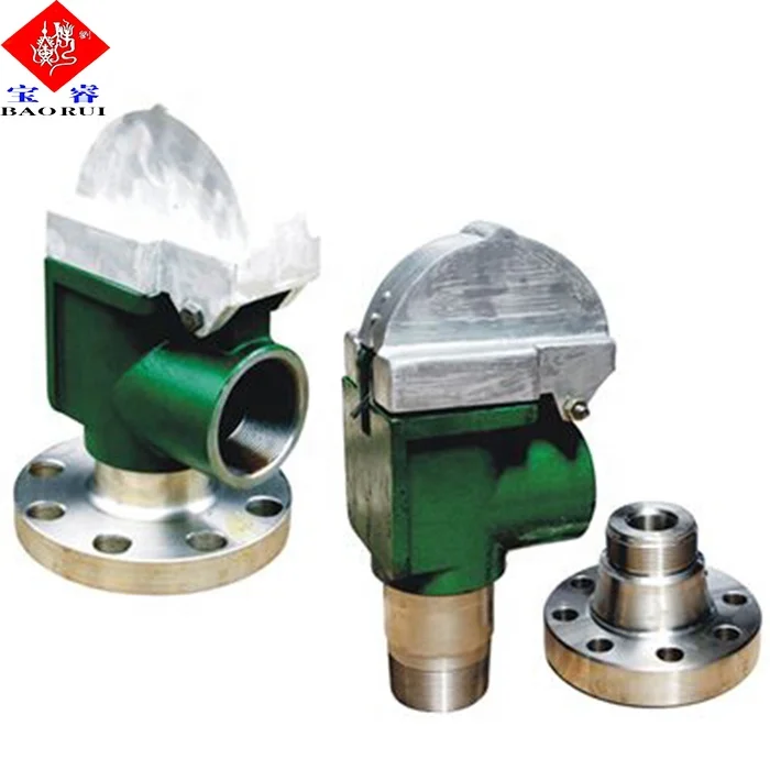
American Block’s collapsing pin relief valve (CPV) is designed to collapse at a specific pressure by utilizing an air-balanced piston that is axially loaded by the pressure load of the pin. While in operation, the status of the valve is easily visible by simply checking the condition of the collapsing pin. The pins are easily changed or replaced in under one minute and does not require extra or special tooling.
REPLACEMENT PINS – The set pressure of the valve is determined by the pin installed. Pins are interchangeable with existing valve designs and offer resistance to pressure fluctuations, environment, and are tamper proof.
SPARE PARTS – American Block offers a complete range of spare components to maintain or repair your valves. All parts are interchangeable with existing valve designs.

R series proportional relief valves provide simple, reliable, overpressure protection for a variety of liquid or gas general-industry applications with set pressures from 10 to 6000 psig (0.7 to 413 bar). They open gradually as the pressure increases and will close when the system pressure falls below the set pressure. The set pressure can be set at the factory or easily adjusted in the field. PRV series proportional safety relief valves are certified to PED 2014/68/EU Category IV, CE-marked in accordance with the Pressure Equipment Directive as a safety valve according to ISO-4126-1, and factory-set, tested, locked, and tagged with the set pressure.
Swagelok bleed valves can be used on instrumentation devices such as multivalve manifolds or gauge valves to vent signal line pressure to atmosphere before removal of an instrument or to assist in calibration of control devices. Male NPT and SAE end connections are available. Purge valves are manual bleed, vent, or drain valves with NPT, SAE, Swagelok tube fitting, or tube adapter end connections. A knurled cap is permanently assembled to the valve body for safety. Both bleed and purge valves are compact for convenient installation.


 8613371530291