
replace mud pump motor maintenance programs for sale

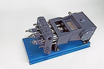
Mud Pumps come in both electric and gas / diesel engine drive along with air motors. Most of these pumps for mud, trash and sludge or other high solids content liquid dewatering, honey wagon and pumper trucks. Slurry and mud pumps are often diaphragm type pumps but also include centrifugal trash and submersible non-clog styles.
WARNING: Do not use in explosive atmosphere or for pumping volatile flammable liquids. Do not throttle or restrict the discharge. Recommend short lengths of discharge hose since a diaphragm mud pump is a positive displacement type and they are not built with relief valves.
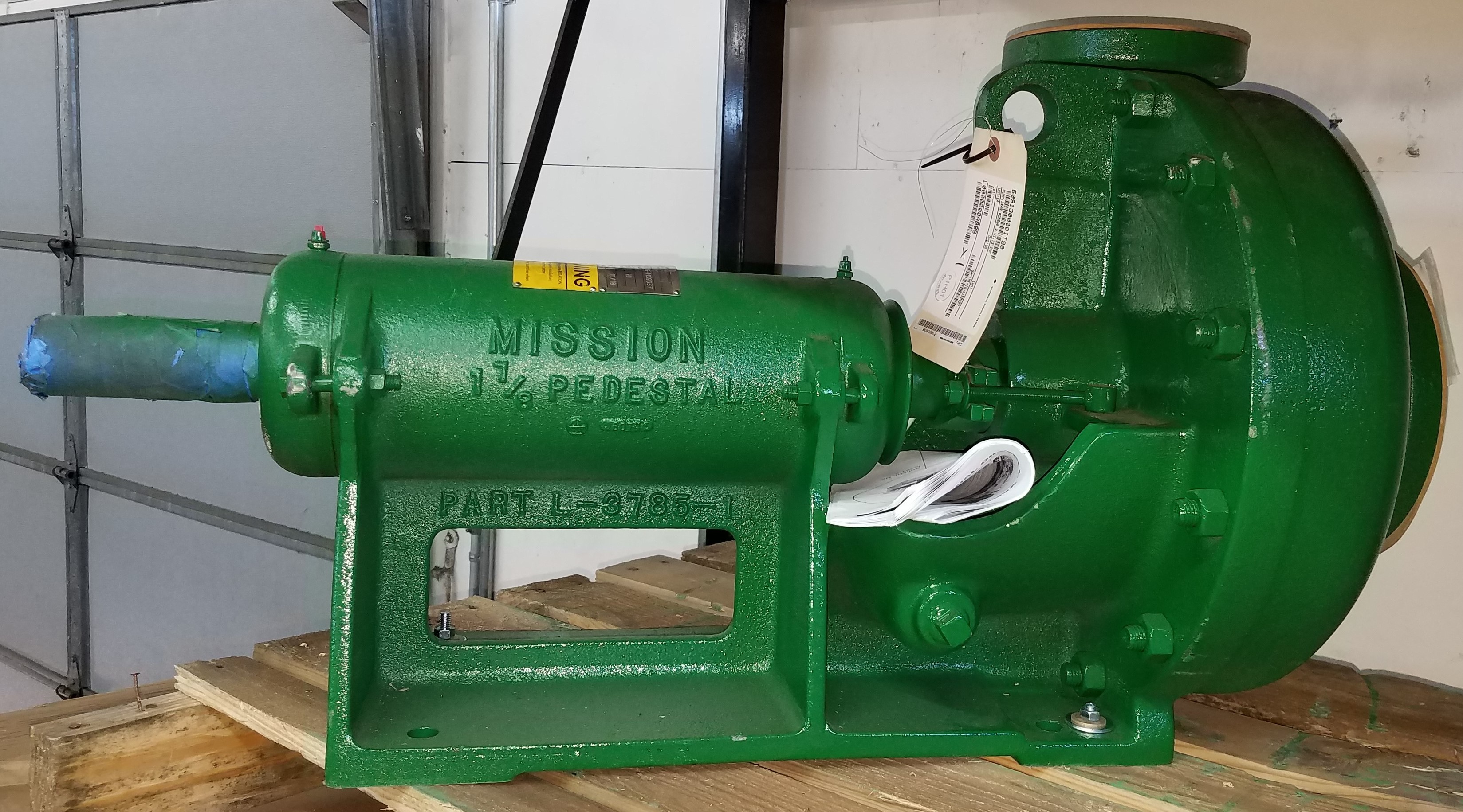
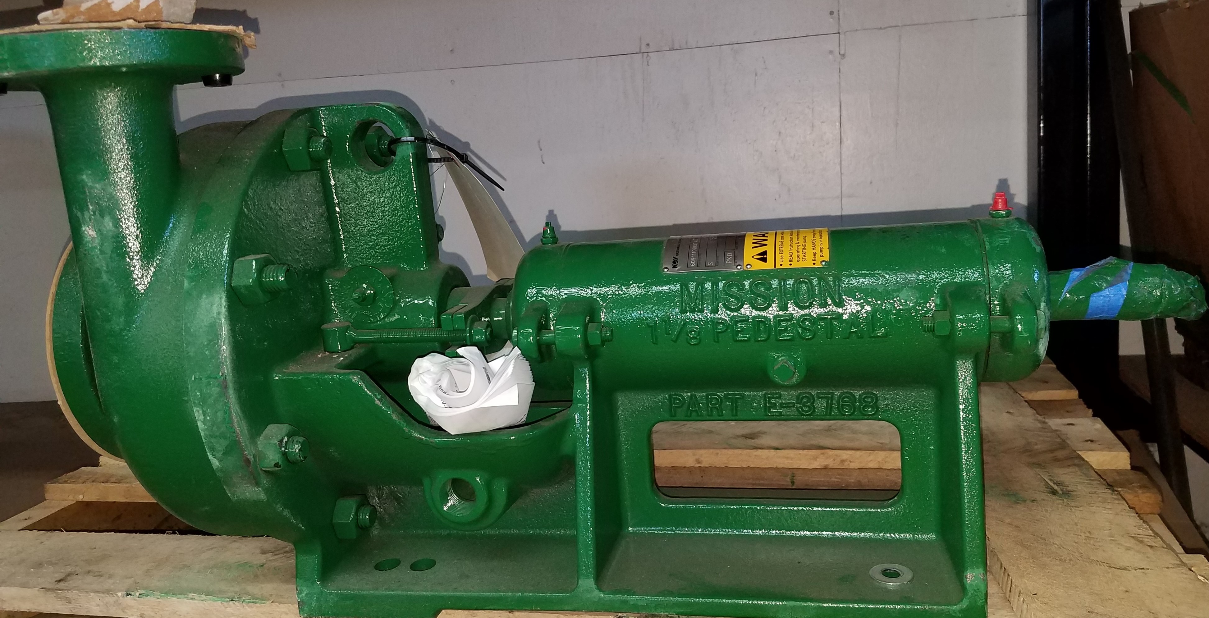
During the 1950’s the Mission” 1780 type “W” pumps were introduced to replace duplex pumps while creating the first low pressure mud system. The use of a high quality concentric type centrifugal pump allowed abrasive fluids to be mixed and transferred while reducing initial and maintenance costs for the drilling industry. The low-pressure mud system with Mission 1 780 Type “W” centrifugal pumps became the industry standard.
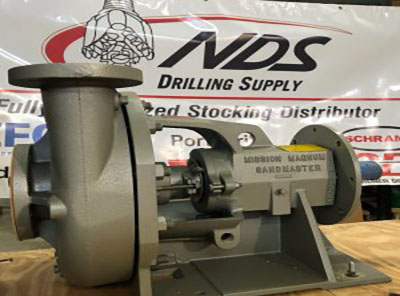
As well depths increased so did the need for heavier mud weights. When the mud weight began exceeding 14 ppg the need for a pump that could withstand greater horsepower loads arose. During the 1970’s Mission organized a design team that engineered the Mission Magnum. The Magnum was designed to have the same footprint, flange locations, and drive shaft diameter as the 1780 “W”. This allowed a 1780 to be replaced by a Magnum without any skid modifications. The Magnums were originally engineered with a 2-1/2″ shaft (3″ between the bearings), double row bearings with an engineered life of over 2 years at 200 HP, larger impellers and heavier frames. The Magnum allowed drilling contractors to upgrade their centrifugal pumps and mix heavier fluids.
The National Oilwell Varco” Mission centrifugal pump line has proven to be the best centrifugal design for handling abrasive mud. This pump line offers a broad selection of innovative features for a variety of routine, demanding, abrasive and corrosive applications. These pumps are designed for a wide range of flow rates, from a few gallons per minute to thousands of gallons per minute.
Each pump contains the finest materials, engineering and craftsmanship available in the industry. Described are like features of these pump lines and unique features are described on the following pages.
National Oilwell Varco utilizes unique design features developed for slurries. Three major differences from most pump designs include the concentric casing, wider impellers and increased re-circulation areas. Each feature contributes to reducing wear when handling abrasive fluids.
All of the pumps feature a concentric casing. This casing averages 37% thicker than conventional pump casings, and up to 50% thicker for the larger, mud pumping models. They are pressure rated at 1 .5 times the flange rating and are designed with a 1 /8″ erosion allowance. The concentric style casing has proven to offer the greatest pump life and reduced downtime. The walls of a concentric style casing are an equal distance from the impeller throughout the impeller circumference, which results in a smooth flow pattern. A volute style casing has a cutwater point that disturbs the fluid flow pattern creating an eddy. The concentric casing eliminates vibration, turbulence and aeration that is caused by the cutwater point in conventional volute pumps. It also reduces the high bearing loads and shaft deflection even at near shutoff flows.
The shaft is much larger in diameter than conventional pump shafts for heavy-duty performance, minimum deflection and increased operating life of the seal or packing. With a 2-1/2″ diameter at the seal area and 3″ diameter between the bearings these pumps can be direct connected or belt driven.
The shaft area under the packing is protected by a replaceable, hook type sleeve with one end free to expand with temperature variation. This sleeve can be replaced in the field without shaft removal.

Distributor of heavy duty submersible mud, sand, sludge & slurry pumps. Specifications of pumps include 5 hp to 30 hp motor, three phase, 208 V to 575 V, 6.8 A to 39 A, 3 in. to 6 in. NPT sizes, 38 ft. to 134 ft. head size & 475 gpm to 1,690 gpm flow rate. Features include impellers, wear plates & agitators made from abrasive resistant 28 percent chrome iron, process hardened ductile iron volutes casted with thick walls, class H motor insulation, double silicon carbide mechanical seals, heavy duty lip seal & stainless steel shaft & shaft sleeve. Sand, sludge & slurry pumps are used in mines, quarries, dredging, coal & ore slurries, sewage treatment plants & steel mills. UL listed. CSA approved. Meets OSHA standards.
Pumps are often designed to operate at a single point known as the Best Efficiency Point (BEP). As components begin to wear, a pumps performance begins to decline, with operation away from this point leading to issues such as accelerated bearing or seal wear, vibration, excess temperature rise or cavitation. Quite often declining performance can start gradually, before quickly accelerating until failure if performance issues are not addressed in a timely fashion.
Corrective Maintenance is undertaken when failure has occurred. The unit may be leaking, efficiency reduced, pump stopped or motor tripped, leading to loss of production resulting in an urgent situation where parts must be sourced and fitted quicky.
Preventative Maintenance is inspection and repair scheduled at specific intervals (daily, weekly, monthly, yearly) or based on the number of hours run. Visual inspections are made externally and internally by dismantling the unit, replacing seals such as gaskets and mechanical seals, with pump parts checked for wear.
Differential Pressure:Check the operating pressure by calculating the difference between the inlet and outlet pressure of the pump ensuring it is operating on curve.
Excess Temperature – Check motor, bearing and casing temperature. Thermal imaging cameras can detect excess temperature quickly, without stoppage, dismantling or contact with the unit.
The “6 to 1 Rule” discovered by John Day Jr, (Manager of Engineering & Maintenance at Alumax South Carolina stated that the ideal ratio of Proactive Maintenance (PM) to Corrective Maintenance (CM) should be 6 to 1 - 6 PM checks to 1 RM check. If your ratio is below this then according to his theory it is being inspected too infrequently, above and inspections are too frequent.
Although Proactive Maintenance can seem to avoid the urgent costs and downtime associated with reactive maintenance, PM maintenance costs can be high due to the cost of labour in dismantling of complicated designs such as Progressing Cavity, or Triplex Plunger pumps which are often time consuming to maintain with more than one person required to undertake work.
On dismantling units, some seals require replacing regardless of condition, and excess spares can be required in case of gasket entrapment during assembly. Rental of specialist lifting equipment may be required and there can be situations where when inspected, pump parts do not require replacement.
MonitoringThe ideal situation is to ensure components are replaced before failure but not so far in advance that they have experienced little wear with valuable time spent on inspecting components which are otherwise fine.
This can be achieved through a monitoring device, where when the right data is collected, pump failure can be anticipated between 3 and 12 months in advance with an 80-95% accuracy.
With the average lead time on DN100 pumps, and units over 5 years old being 3 months or more, it is essential that spares are either on the shelf or failure is anticipated through advance ordering.
There are hazards during any maintenance activity. Always ensure the correct PPE is worn before attempting repair, that sufficient expertise is on hand and chemical data sheets of any fluid being pumped are checked prior to undertaking work. A full risk assessment should be completed in advance.
Hazardous FluidsIrritation, Chemical burns, ignitionEnsure when pump is opened the unit is cool, not pressurized, ignition sources are not present, and any fluids spilt are contained.
If inspection has been neglected for some time, then additional parts may require replacing than had the unit been inspected earlier, with some pump parts becoming beyond economical repair.
Enables planned work to be undertaken during lower activity levels and at lowest cost & risk.Pump has to be crucial within a process or above a certain size for monitoring to be cost effective
Thread Sealant –The use of semi-permanent thread sealant will ensure vitality important threaded fasteners such as bolts or screws on shafts, couplings or pump casings do not self-loosen due to vibration and become disengaged.
Interchangeable Spares –Our range of pumps are modular in design utilizing interchangeable spares, meaning on site stock holding of parts can be reduced by up to 80% further reducing slow moving stock.
Repair & Replace –Choosing to repair an existing pump within a process of vital importance, as well as replace, is a strategy we recommend for maximizing plant efficiencies and reducing downtime. Should unexpected pump failure occur, your process can be restored quickly.
Checklists & Logs –The use of checklists and logs ensures a fully repeatable process ensuring important maintenance intervals are not missed. Logs can provide valuable insight and reveal a pattern before failure occurs enabling easier troubleshooting.
indicates which areas should be checked, but note that a units maintenance routine is dependent on several factors such as hours of operation, duty, aggressiveness of pump medium, rpm of motor, temperature, inlet conditions and location of equipment.
I wrote a series of columns last year and into January this year on well and pump rehabilitation and methods to improve the operating efficiency in both. This month, as a start to a two-part series and a logical continuation to the topic, I’ll expand the discussion outlining my concept of a well and pump preventive maintenance program with suggested procedures and recommended intervals.
As we launched this new enterprise, we decided to offer a preventive maintenance program on a trial basis. This would be our way of introducing and acquainting ourselves to a previously unknown base of new clients, introducing our new division to our existing clients, and as a way of gaining a full understanding of each water system’s particular needs.
Many of these newly discovered clients, especially local smaller water districts and cities, informed me they had wanted to implement some type of preventive maintenance program for their facility, but didn’t know where to start.
The new preventive maintenance program was more than a method of gaining new business for our firm, especially since the late 1970s were also somewhat sluggish in the local irrigation business. Diversifying and expanding into the municipal and commercial water systems market not only provided badly needed revenue, but allowed us to keep current personnel who might otherwise have been laid off or assigned reduced hours during long winter periods.
Since we were already a long-established water systems firm, moving into this larger and slightly different market did not require substantial retraining or expansion of our service staff. We were also able to use our existing equipment and rolling stock, particularly our service vehicles and pump hoists.
As we moved cautiously into developing a preventive maintenance program for the various clients, one thing became rapidly apparent. The program was going to have to be customized and tailored for each client and the specific needs and number of pumps for each water purveyor. For systems with multiple well and pump stations, this meant we had to individualize the program for each client.
Although I was in charge and responsible for this new division—which included my cultivating new clients, submitting bids and proposals, and performing engineering and design—I was still young and didn’t wish to simply come out of the field and into the office to assign the maintenance and troubleshooting to the other employees. So, for the first four years of this new enterprise I alternated between field work and office work.
This not only helped me expand my skills in field work and troubleshooting, but allowed me the opportunity to visit and work with many of the new and diverse water system clients we gained throughout western Oregon. Eventually, the time and effort required to split my duties became more than I could reasonably handle, but those years were instrumental as they allowed me to learn new techniques, expand my troubleshooting skills, and increase my knowledge of water wells, pumps, and electrical and hydraulic theory.
Before actually embarking on a new preventive maintenance (PM) program, we first had to decide how often to recommend individual site visits and develop some type of database to routinely document each individual client and their water system facilities, as well as track each PM and service procedure conducted at each site and for each unit.
As far as building a database, after considering various methods of record keeping I settled on using a single master file for each client. Each file included information on each separate well and pump station. Each was assigned a unique identification code with the specific details of each facility recorded on “master data sheets” (Figures 1, 2, 3).
The PM program was originally envisioned, structured, and priced to be a fairly rapid “in and out” to gather and record the most critical information such as static and operating (pumping water level) conditions of each well and pump and to conduct general maintenance on individual pump and driver units within a pumping plant. Therefore, it was important to provide a uniform set of tasks and criteria to follow and evaluate what was needed without spending unnecessary time or effort on less important or trivial tasks.
Determining and maintaining a reasonable, uniform cost for a PM program was also vital since we could not effectively sell the program to most clients solely from harping on the advantages gained from potential energy savings and improving pump efficiency—at least not in 1979.
To effectively sell and conduct the program to many water systems, it was important to stress we would keep each site visit meaningful and the cost to a minimum by concentrating on just the primary elements of an effective PM program. These elements included: (1) performing necessary routine maintenance at appropriate intervals; (2) determining the current efficiency and operating condition of each pump and motor; (3) identifying and heading off any serious situations with an individual unit that could result in significant downtime and higher repair costs if not addressed soon; and (4) maintaining the inspection reports and records as a collection of current and past data within a master file.
The site visit field form was developed specifically to act as a guideline of the tasks the technician was expected to perform on each unit, each in a fundamental order. By using this initial form over the first to three months of the trial PM program, we were able to quickly determine the typical cost for a single pump station inspection and thereafter apply that unit cost to pump stations with multiple units.
Since many municipal or industrial pumping plants or stations consist of three to four separate units in total, especially those found in water booster or wastewater pump stations, we were able to expand the horizontal use of each form to permit entering up to four separate units on a single sheet.
As important to booster pump stations as this program was, the primary selling point was made to those clients with wells and well pumps or wastewater pumps. Since many wells and well pumps can exhibit a sudden failure due to years of ignorance or lack of maintenance, this program permitted a routine examination and tracking of the well’s pumping water level and the operating condition of the well pump and driver (usually an electric motor).
For example, by checking the static and pumping levels of each well during each visit around the same time each year, we were able to quickly develop an accurate, in-house database on seasonal water levels in most regions of western Oregon and the Willamette Valley.
This type of inspection was particularly important for installations using submersible pump motors since periodic examination of the motor’s insulation resistance often provided a yardstick of a motor’s current condition, or more importantly, any progressive decline.
If this occurred, it usually provided the client with advance notice in one to two years this unit was heading for or nearing failure. This provided enough notice to the client to permit an orderly and scheduled repair or replacement of the motor rather than a rushed and more expensive emergency approach.
Although we were generally careful to require all field data and information be vetted and approved by the engineering department before contacting the client, we did demonstrate to each technician how to determine and record a few basic field observations and calculations. These included static and pumping water levels from wells along with water horsepower, input horsepower, and plant efficiency from pumping units. These were often requested by the clients, particularly when the they were present for the inspections.
Although our original PM program was developed and implemented for both potable and wastewater pumping systems, since Water Well Journal primarily focuses on wells and well pump systems, we will limit this discussion to this group.
This means each field technician must be properly trained and observant in electrical, mechanical, and confined space safety. The most basic of these is always observing OSHA’s mandated “lock out/tag out” procedures for protection against errant automatic or manual starting of electrical motors or engines (drivers) used to drive pumps. This not only protects from possible electrical shocks, but additional forms of injury that could occur. An example that could occur is a pump starting while the tech is repacking or greasing it or changing the motor oil.
Finally, many water systems use potentially harmful chemicals and feed systems in their facilities (high-strength chlorine, acids, or caustics) or other ancillary systems interconnected to the pump start/run signal. Even though locking out the pump motor may prevent its start and operation, it may not necessarily disconnect or disable these other systems.
To help meet your professional needs, this column covers skills and competencies found in DACUM charts for drillers, pump installers, and geothermal contractors. PI refers to the pumps chart. The letter and number immediately following is the skill on the chart covered by the column. This column covers: PIE-18, 22: PIF-2, 3, 4, 5, 6, 7: PIG-3, 8, 10 More information on DACUM and the charts are available at www.NGWA.org/Certification and click on “Exam Information.”
The next area with a type of hazard occurs from exposure to confined spaces. Although most potable water pumping units are not located in regulated confined spaces, many control valves and other equipment are commonly situated in tanks or underground vaults or chambers. Accumulated or released vapors or gases within these environments, especially those heavier than air in underground vaults or facilities, can overcome a worker within seconds. Recognizing these potential hazards and equipping each employee with a gas sniffer or alarm to notify the tech should hazardous or flammable gases or a low oxygen level exist and an approved breathing mask/tank is recommended.
In conclusion, it is vitally important anyone charged with conducting preventive maintenance and service be fully trained and capable in understanding and performing the procedural and safety measures required for each unit in each pumping station and observe the proper shutdown (lockout/tagout), service, and reactivation protocols.
This concludes this first installment on setting up a well and pump maintenance program. Next month, we’ll wrap up with an overview on setting up the forms and performing the field work.
In addition, certain online technical applications or other interactions you have with Power Zone Equipment may require the entry of business and technical data. By providing the requested information, you are consenting to the processing and storage of such information by Power Zone Equipment. Unless Power Zone Equipment is advised that you want this information removed from Power Zone Equipment’s server, such information may be retained by Power Zone Equipment and used for future commercial communications. A request for removal of this information can be made at the contact information provided below. Power Zone Equipment will take all reasonable precautions to assure that no such information will be provided or divulged to other third parties, except, if applicable, those third parties performing site hosting, maintenance, and related site service activities.

DistributionNOW has a full fleet of field service and repair assets across a large geography of North America. This includes full pump repair in the field, installation and startup, as well as preventative maintenance practices for install pumping equipment in the field. We have decades of experience serving the oil & gas, power generation, petrochemical and municipal markets. Our experts can extend the life of your equipment with our maintenance programs, in-house repairs, upgrades and replacement parts. We have full capability of in-house machining and repair of pumps and their components.

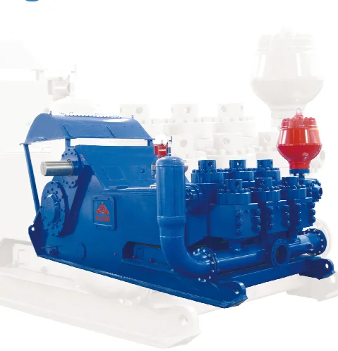
Many things go into getting the most life out of your mud pump and its components — all important to extend the usage of this vital piece of equipment on an HDD jobsite. Some of the most important key points are covered below.
The most important thing you can do is service your pump, per the manufacturer’s requirements. We get plenty of pumps in the shop for service work that look like they have been abused for years without having basic maintenance, such as regular oil changes. You wouldn’t dream of treating your personal vehicle like that, so why would you treat your pump like that.
Check the oil daily and change the oil regularly. If you find water or drilling mud contamination in the oil, change the oil as soon as possible. Failure to do so will most likely leave you a substantial bill to rebuild the gear end, which could have been avoided if proper maintenance procedures would have been followed. Water in the oil does not allow the oil to perform correctly, which will burn up your gear end. Drilling mud in your gear end will act as a lapping compound and will wear out all of the bearing surfaces in your pump. Either way it will be costly. The main reasons for having water or drilling mud in the gear end of your pump is because your pony rod packing is failing and/or you have let your liners and pistons get severely worn. Indication of this is fluid that should be contained inside the fluid end of your pump is now moving past your piston and spraying into the cradle of the pump, which forces its way past the pony rod packing. Pony rod packing is meant to keep the oil in the gear end and the liner wash fluid out of the gear end. Even with brand new packing, you can have water or drilling fluid enter the gear end if it is sprayed with sufficient force, because a piston or liner is worn out.
There is also usually a valve on the inlet of the spray bar. This valve should be closed enough so that liner wash fluid does not spray all over the top of the pump and other components.
Liner wash fluid can be comprised of different fluids, but we recommend just using clean water. In extremely cold conditions, you can use RV antifreeze. The liner wash or rod wash system is usually a closed loop type of system, consisting of a tank, a small pump and a spray bar. The pump will move fluid from the tank through the spray bar, and onto the inside of the liner to cool the liner, preventing scorching. The fluid will then collect in the bottom of the cradle of the pump and drain back down into the collection tank below the cradle and repeat the cycle. It is important to have clean fluid no matter what fluid you use. If your liners are leaking and the tank is full of drilling fluid, you will not cool the liners properly — which will just make the situation worse. There is also usually a valve on the inlet of the spray bar. This valve should be closed enough so that liner wash fluid does not spray all over the top of the pump and other components. Ensure that the water is spraying inside the liner and that any overspray is not traveling out of the pump onto the ground or onto the pony rod packing where it could be pulled into the gear end. If the fluid is spraying out of the cradle area and falling onto the ground, it won’t be long before your liner wash tank is empty. It only takes a minute without the cooling fluid being sprayed before the liners become scorched. You will then need to replace the pistons and liners, which is an avoidable costly repair. Make a point to check the liner wash fluid level several times a day.
Drilling fluid — whether pumping drilling mud, straight water or some combination of fluid — needs to be clean. Clean meaning free of solids. If you are recycling your fluid, make sure you are using a quality mud recycling system and check the solids content often throughout the day to make sure the system is doing its job. A quality mud system being run correctly should be able to keep your solids content down to one quarter of 1 percent or lower. When filling your mud recycling system, be sure to screen the fluid coming into the tanks. If it is a mud recycling system, simply make sure the fluid is going over the scalping shaker with screens in the shaker. If using some other type of tank, use an inline filter or some other method of filtering. Pumping out of creeks, rivers, lakes and ponds can introduce plenty of solids into your tanks if you are not filtering this fluid. When obtaining water out of a fire hydrant, there can be a lot of sand in the line, so don’t assume it’s clean and ensure it’s filtered before use.
Cavitation is a whole other detailed discussion, but all triplex pumps have a minimum amount of suction pressure that is required to run properly. Make sure this suction pressure is maintained at all times or your pump may cavitate. If you run a pump that is cavitating, it will shorten the life of all fluid end expendables and, in severe cases, can lead to gear end and fluid end destruction. If the pump is experiencing cavitation issues, the problem must be identified and corrected immediately.
The long and the short of it is to use clean drilling fluid and you will extend the life of your pumps expendables and downhole tooling, and keep up with your maintenance on the gear end of your pump. Avoid pump cavitation at all times. Taking a few minutes a day to inspect and maintain your pump can save you downtime and costly repair bills.

The Liberty Process LL8 Progressive Cavity Pump is ideal for abrasive pumping applications such as drilling fluids with sand and grit common in fracking operations. As a Mud Pump, the LL8 Series is a popular model on many mobile pumping rigs in use today. Replacement mud pump parts are available as well from our stock and work on other popular manufacturers models.
LL8 parts are direct drop in aftermarket replacements that work with the *Moyno® L8 series, the *Tarby® TL8 series and *Continental® CL8 Series*. The Liberty unit is a low-cost, maintenance free, dependable drop-in replacement progressive cavity unit.
The Liberty LL8 is a standard flanged pump design manufactured with cast iron or 316 stainless steel pump casings designed in 1, 2, and 3 stages for 75, 150 and 225 psi discharge pressures and a flow rate of 18 up to 100 GPM.
The LL8 is a modular design with simple hardened pinned joint drive assembly. LL8 Rotors are typically hardened tool steel or 316 stainless steel with a hard chrome plating for long life in abrasive pumping applications.
All other wetted parts are either carbon steel or 316 stainless steel. Stators are available in many elastomer materials such as Buna Nitrile, Natural Rubber, EPDM and Viton. The standard seal design is a set of gland packing with a lantern ring set and flush connections. Mechanical seal options for this progressive cavity pump are readily available.
The LL8 represents one of the most popular progressive cavity pumps available for the transport of drilling mud with easily replaceable in-stock parts.

Pumps are vital to industries including water treatment and wastewater facilities, power generation, oil and gas, food processing and more. In the oil and gas industry, the uptime of industrial pumps is especially critical. The total world consumption of global petroleum and other liquid fuels averaged 92.30 million barrels per day in 2020, according to the U.S. Energy Information Administration. That total has risen by approximately 5 million in 2021 and will continue to grow in 2022. Any unplanned downtime can impact the ability to meet this growth.
There are three basic types of pumps, and they are classified by how they transport fluid: positive-displacement, centrifugal and axial-flow. Pumps can experience several different types of failures, including cavitation, bearing failures and seal failures, among others. In oil and gas, conditions in which pumps operate are often challenging, dirty and hazardous, resulting in wear and tear. Failure of these pumps not only results in unexpected operation delays and increased costs, but it can lead to dangerous oil and gas leaks, impacting labor safety and the environment. To avoid these unexpected failures, many companies increase preventative maintenance and create aggressive inspection schedules. These practices, however, can sometimes lead to unnecessary part replacement, maintenance costs and labor.
Others may rely on condition-based maintenance, which focuses on maintenance performed after monitoring real-time data and detecting unacceptable condition levels. However, this may not come with the advanced warning needed to prevent impending failure events or avoid downtime. By taking a predictive approach, past maintenance data and current sensor measurements can be used to determine early signs of failure, allowing companies to perform maintenance only at the exact time it is needed.
IMAGE 1: An example of a deployed solution for predictive monitoring and failure detection of critical mud pumps in the oil and gas industry. (Images courtesy of Predictronics)
Developing and deploying a predictive maintenance solution for pumps is challenging. It requires a combination of sensing and instrumentation expertise, domain knowledge, and a practical perspective on applying machine learning and analytics for predictive monitoring. The instrumentation aspect is crucial since this data will be analyzed and will serve as the foundation of the actionable information. The decisions made from this information include what maintenance actions are needed and when they should be taken given the current pump health, as well as any trends or patterns that could emerge.
Vibration is typically the most crucial signal to use for monitoring the condition of a pump, but information on the rotating or reciprocating motion is also useful, especially for performing the more advanced signal processing methods. In addition, pressure and flow rate measurements are important for understanding pump operation and providing context for understanding the vibration data. A balance must be struck between the benefit of including these important measurements versus the hardware and implementation costs of doing so. This challenge is especially true for vibration sensors. Domain expertise is needed to place a minimal set of sensors to keep the hardware cost down and monitor the pump properly and accurately.
When handling the analytics, it is challenging to apply machine learning for this application without any domain-specific preprocessing and signal processing steps. Typically, pump failures are rare, so using a supervised machine learning model is not typically practical. Instead, a combination of domain-specific feature extraction methods for the vibration signals coupled with a baseline-based anomaly index machine learning algorithm is a more reasonable approach. The deployment and user interface should be closely aligned with the industrial use case and expected user, as well as the problem being solved. For some applications, it is not feasible to transmit the data to a remote monitoring center or central server, requiring the analytics and deployment to be performed closer to the data source.
A global oil and gas contractor with a specialty in automated drilling equipment and rig components wanted to develop a health monitoring solution for its mud pumps in the field. The contractor wanted to reduce unplanned downtime and unexpected failures. Not only did the company want to prevent these failure events, but they also wanted to distinguish between anomalies caused by maintenance issues and anomalies due to sensor issues.
By working with a predictive analytics company, this client sought to differentiate these anomalies, address the pump failures, and validate the solution by utilizing the induced fault data collected on its test rig.
The user provided the analytics company with a year’s worth of historical data from test bed data sets and sensors on the piston, suction and discharge mechanisms on two pumps in the field. The team of analytics experts was able to pull crucial features from the data by considering vibration patterns in the frequency and time-frequency domain. These features were integral to the development of health assessment models. The models then helped determine key indicators of pump seal failure, as well as establish the accuracy and necessity of the sensors.
By using advanced signal processing and vibration-based pattern recognition, the health monitoring system was able to detect and diagnose pump failures. This solution provided a baseline health assessment, failure identification and pattern recognition diagnosis capabilities.
The predictive analytics company was able to identify potential issues, as well as establish the best locations for sensor placement. The final solution predicted mud pump failure at least one day in advance, providing the data needed to take action and proactively perform maintenance. This approach helped reduce downtime, increase productivity, improve safety and prevent leaks.
Criticality analysis is essential in order to select the pumps for which predictive maintenance solutions can best be applied and to choose a solution that can provide the most value.
After determining the target pumps, the most critical failure modes should be identified, along with any relevant maintenance records for unplanned and planned downtime.
Based on the data and common failure modes, determine sensor placement and what, if any, additional sensors need to be added to the monitored pumps for the predictive solution.
These initial steps are essential when partnering with a technology provider and can help companies develop and adopt a predictive maintenance solution for their pumps that is robust and accurate.
The drilling industry has roots dating back to the Han Dynasty in China. Improvements in rig power and equipment design have allowed for many advances in the way crude oil and natural gas are extracted from the ground. Diesel/electric oil drilling rigs can now drill wells more than 4 miles in depth. Drilling fluid, also called drilling mud, is used to help transfer the dirt or drill cuttings from the action of the drilling bit back to the surface for disposal. Drill cuttings can vary in shape and size depending on the formation or design of the drill bit used in the process.
Watch the video below to see how the EDDY Pump outperforms traditional pumps when it comes to high solids and high viscosity materials commonly found on oil rigs.
The fluid is charged into high-pressure mud pumps which pump the drilling mud down the drill string and out through the bit nozzles cleaning the hole and lubricating the drill bit so the bit can cut efficiently through the formation. The bit is cooled by the fluid and moves up the space between the pipe and the hole which is called the annulus. The fluid imparts a thin, tough layer on the inside of the hole to protect against fluid loss which can cause differential sticking.
The fluid rises through the blowout preventers and down the flowline to the shale shakers. Shale shakers are equipped with fine screens that separate drill cutting particles as fine as 50-74 microns. Table salt is around 100 microns, so these are fine cuttings that are deposited into the half-round or cuttings catch tank. The drilling fluid is further cleaned with the hydro-cyclones and centrifuges and is pumped back to the mixing area of the mud tanks where the process repeats.
The drill cuttings contain a layer of drilling fluid on the surface of the cuttings. As the size of the drill cuttings gets smaller the surface area expands exponentially which can cause rheological property problems with the fluid. The fluid will dehydrate and may become too thick or viscous to pump so solids control and dilution are important to the entire drilling process.
One of the most expensive and troubling issues with drilling operations is the handling, processing, and circulation of drilling mud along with disposing of the unwanted drill cuttings. The drilling cuttings deposited in the half round tank and are typically removed with an excavator that must move the contents of the waste bin or roll-off box. The excavators are usually rented for this duty and the equipment charges can range from $200-300/day. Add in the cost for the day and night manpower and the real cost for a single excavator can be as much as $1800/day.
Using the excavator method explained above, the unloading of 50 barrels of drill cuttings from the half round can take as long as two hours. This task is mostly performed by the solids control technicians. The prime duty for the solids control technicians is to maintain the solids control equipment in good working order. This involves maintenance for the equipment, screen monitoring and changing, centrifuge adjustments, and retort testing to prepare a daily operational summary of the solids control program.
Offshore drilling rigs follow a similar process in which the mud is loaded into empty drums and held on the oil platform. When a certain number of filled drums is met, the drums are then loaded onto barges or vessels which take the drilling mud to the shore to unload and dispose of.
Oil field drilling operations produce a tremendous volume of drill cuttings that need both removal and management. In most cases, the site managers also need to separate the cuttings from the drilling fluids so they can reuse the fluids. Storing the cuttings provides a free source of stable fill material for finished wells, while other companies choose to send them off to specialty landfills. Regardless of the final destination or use for the cuttings, drilling and dredging operations must have the right high solids slurry pumps to move them for transport, storage, or on-site processing. Exploring the differences in the various drilling fluids, cutting complications, and processing options will reveal why the EDDY Pump is the best fit for the job.
The Eddy Pump is designed to move slurry with solid content as high as 70-80 % depending on the material. This is an ideal application for pumping drill cuttings. Drill cuttings from the primary shakers are typically 50% solids and 50% liquids. The Eddy Pump moves these fluids efficiently and because of the large volute chamber and the design of the geometric rotor, there is very little wear on the pump, ensuring long life and greatly reduced maintenance cost for the lifetime of the pump.
plumbed to sweep the bottom of the collection tank and the pump is recessed into a sump allowing for a relatively clean tank when the solids are removed. The Eddy Pump is sized to load a roll-off box in 10-12 minutes. The benefit is cuttings handling is quicker, easier, safer, and allows for pre-planning loading where the labor of the solids control technician is not monopolized by loading cuttings. Here, in the below image, we’re loading 4 waste roll-off bins which will allow the safe removal of cuttings without fear of the half-round catch tank running over.
Mud cleaning systems such as mud shaker pumps and bentonite slurry pumps move the material over screens and through dryers and centrifuges to retrieve even the finest bits of stone and silt. However, the pump operators must still get the raw slurry to the drill cuttings treatment area with a power main pump. Slurry pumps designed around the power of an Eddy current offer the best performance for transferring cuttings throughout a treatment system.
Options vary depending on whether the company plans to handle drill cuttings treatment on-site or transport the materials to a remote landfill or processing facility. If the plan is to deposit the cuttings in a landfill or a long-term storage container, it’s best to invest in a pump capable of depositing the material directly into transport vehicles. Most dredging operations rely on multiple expensive vacuum trucks, secondary pumps, and extra pieces of equipment.
Using an EDDY Pump will allow a project to eliminate the need for excavators/operators to load drill cuttings, substantially lowering both labor and heavy equipment costs. The EDDY Pump also allows a company to eliminate vacuum trucks once used for cleaning the mud system for displacing fluids. Since the pump transfers muds of all types at constant pressure and velocity throughout a system of practically any size, there’s little need for extra equipment for manual transfer or clean up on the dredge site.
The EDDY Pump can fill up a truck in only 10 minutes (compared to an hour) by using a mechanical means such as an excavator. For this reason, most companies can afford one piece of equipment that can replace half a dozen other units.
This application for the Eddy Pump has the potential to revolutionize the drilling industry. Moving the excavator out of the “back yard” (the area behind the rig from the living quarters) will make cuttings handling a breeze. Trucking can be easier scheduled during daylight hours saving on overtime and incidences of fatigued driving. Rig-site forklifts can move the roll-off boxes out of the staging area and into the pump loading area. The operator can save money on excavators rental, damages, and keep the technician operating the solids control equipment.
The EDDY Pump is ideal for drilling mud pump applications and can be connected directly onto the drilling rigs to pump the drilling mud at distances over a mile for disposal. This eliminates the need for costly vacuum trucks and also the manpower needed to mechanically move the drilling mud. The reasons why the EDDY Pump is capable of moving the drilling mud is due to the hydrodynamic principle that the pump creates, which is similar to the EDDY current of a tornado. This tornado motion allows for the higher viscosity and specific gravity pumping ability. This along with the large tolerance between the volute and the rotor allows for large objects like rock cuttings to pass through the pump without obstruction. The large tolerance of the EDDY Pump also enables the pump to last many times longer than centrifugal pumps without the need for extended downtime or replacement parts. The EDDY Pump is the lowest total life cycle pump on the market.


 8613371530291