
rod bearing for mud pump supplier
A wide variety of mud pump connecting rod options are available to you, such as 1 year, 2 years.You can also choose from new, mud pump connecting rod,As well as from energy & mining, construction works , and machinery repair shops. and whether mud pump connecting rod is 6 months, unavailable, or 3 months.
This website is using a security service to protect itself from online attacks. The action you just performed triggered the security solution. There are several actions that could trigger this block including submitting a certain word or phrase, a SQL command or malformed data.

This website is using a security service to protect itself from online attacks. The action you just performed triggered the security solution. There are several actions that could trigger this block including submitting a certain word or phrase, a SQL command or malformed data.

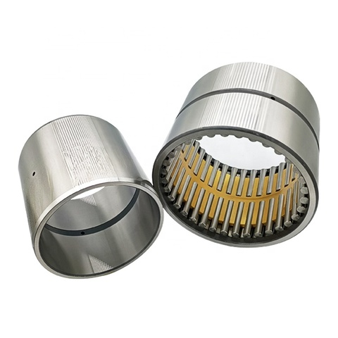
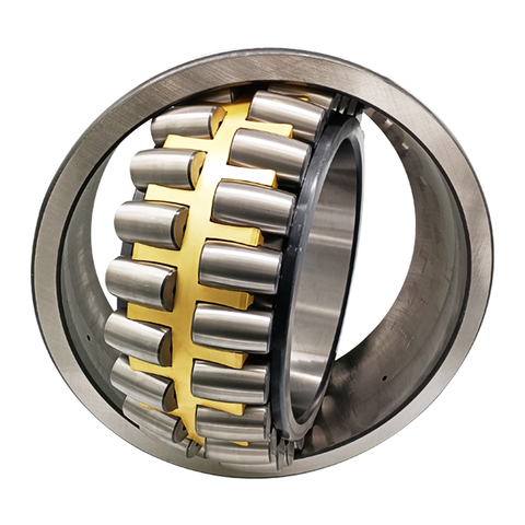
Bearings for petroleum machinery used on the oilfields is our main products, SUP bearing have succeeded in improving the products structure to make the bearings for Oil production & drilling extend the using life. SUP bearing meet rigorous quality demand of oil drilling equipment, and central good quality completely, SUP Bearings for petroleum machinery used on the oilfields applicable to working situation of oil drilling equipment and nature climate.544000 bearing equal to C-7425-B,NUP76658,ADA42603 bearing,used on Emsco(NOV) FB1600 mud pump.
The crankshaft and pinion gear are mounted on low-friction rollers apherical and cylindrical roller bearings,the bearings are lubricated by a dual,splash oil and forced oli lubrication system.
SUP BEARING can offer the mud pump bearings include crankshaft bearings,Drive Shaft Bearings,Connecting Rod Bearings,Crosshead Pin Bearings. You check the following mud pump bearing that SUP BEARING can offer to you:

Since horizontal directional drilling (HDD) work tends to be slower in the winter months, particularly when the ground is frozen, winter is a prime time to inspect the power end of the pump and prevent downtime on the job later.
If one waits until an audible problem can be detected, it is often very expensive to repair. All smaller HDD pumps – 100 hp and smaller — tend to use the same type of internal components regardless of the manufacturer.
The power end should last for years if it is given proper maintenance. Clean lubricant is essential for longevity along with wiper box seals that are in good condition. External influences such as allowing the pistons to leak profusely and or cavitation tend to shorten the life span of the power end components quickly. It is easy to visually inspect the power end components for wear and detect a problem before it becomes very expensive to repair.
The largest load bearing area of the pump is the crosshead pin and bushing area. Wear can be detected by locking the intermittent or piston rod with a pipe wrench and rotating the crank shaft slightly. If one can feel any slack it can only be coming from the pin and bushing or the connecting rod bearing. It then becomes necessary to remove the connecting rod assembly consisting of the connecting rod and cross head. If slack is determined in the pin bushing, it will be necessary to press out the pin and inspect the bushing and the crosshead pin in the eye of the connecting rod. Some manufacturers ship bushings that are designed to fit. Others ship them and they have to be reamed to fit the pin after the bushing is installed. The installation instructions and dimensional fits are provided by the manufacturer in the pump manual.
1. Crankshaft 2. Main bearing 3. Shim set 4. Connecting rod bearing half 5. Crankshaft oil seal 6. Rod cap shim 7. Connecting rod 8. Wrist pin 9. Cross head 10. Intermittent rod 11. Wiper box gland 12. Wiper box seals 13. Wiper snap ring
The next area of concern is the connecting rod bearings themselves. If visual wear can be seen, use a micrometer and measure the crankshaft journals to make sure they are not out of round. If the journals check out, then all is needed is new connecting rod bearings. Some manufactures utilize shims to get the correct fit to the journal. Others provide automotive style bearings that only require correct torque to the rod cap for correct installation. There are pros and cons concerning automotive style vs shim bearings. Shim type bearings does allow for oversized connecting rod bearing should the journals be worn. This allows for turning down the crank journals a few thousands and utilizing a larger connecting rod bearing. If a pump uses automotive style precision bearings and the journals are out of round, it is necessary to replace the crankshaft.
The tapered roller bearing should last for years. If the rollers and races are not pitted, utilizing the same set of roller bearings is allowable. Checking the end play on the crankshaft is a simple task. With the use of a dial indicator, check for the lateral movement of the shaft. It if falls within the manufacturer’s tolerances, nothing needs to be done, If not, then it will be necessary to add or remove shims. Shims packs are provided by the manufacturer so one can get the proper end play on the crankshaft. The shims themselves come in different thickness allowing one to add or remove to get the correct end play.
Wiper box packing keeps the oil within the power frame and external contamination from entering the power end. The packing is easy to inspect and essential for longevity of the power end. The wiper box packing must remain in excellent condition at all times. Allowing the pump to set for extended periods of time or letting external contamination build on the packing shortens the lifespan.
If one waits until an audible problem can be detected, it is often very expensive to repair. All smaller HDD pumps – 100 hp and smaller — tend to use the same type of internal components regardless of the manufacturer.
If the intermittent rod or pony rod becomes scoured, replace it at once. This score mark is a direct path for contamination to enter the power end. Some manufactures utilize intermittent rods that are permanently attached to the cross head. Others utilize rods that are removable and replaceable. It makes no difference which style one has, if the intermittent rod becomes scratched, it must be replaced.
Inspection of the power end allows the owner to dictate when repairs are necessary rather than allowing the pump to dictate during the middle of a job when repair is required. If problems are detected early, repair is relatively inexpensive. If a problem is not detected early, that problem often leads to more unnecessary wear and affects other components of the pump. An early fix to any problem is relatively inexpensive. Allowing the problem to continue can often cost several thousands of dollars and downtime on a job.

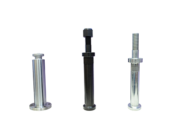
Our connecting rods are made from high specification alloy steel. White Star connecting rods are machined with high precision to ensure the alignment between the crankshaft and the crosshead.
The function of the crankshaft is to turn the thrust from the piston rod into rotating torque, turn the piston"s reciprocating linear motion into a circular motion of the crankshaft, and then send the engine torque to the transmission system through the flywheel; it also drives the engine"s valve Institutions and other auxiliary devices.
The crankshaft is mainly composed of the front end (or free end) of the crankshaft, connecting rod journal, main journal, crank, balance weight, and rear end flange (or power output end) of the crankshaft. A crankshaft timing gear is mounted at the front end of the crankshaft, and a flywheel is mounted at the rear end (some engines also have a balance weight).
According to the number of main journals of the crankshaft, the crankshaft can be divided into two types: full-supported crankshaft and non-full-supported crankshaft. According to its structure, it can be divided into three types: integral forging, integral casting, and combination. Cast iron and steel
Jun272016CROSSHEAD BEARING (PART NO - 202-2195) (MAT CODE - 210008820) (SPARES OF WHITE STAR MAKE MUD PUMPS)United StatesNhava Sheva SeaNOS4588,786147,197

Legal status (The legal status is an assumption and is not a legal conclusion. Google has not performed a legal analysis and makes no representation as to the accuracy of the status listed.)
Current Assignee (The listed assignees may be inaccurate. Google has not performed a legal analysis and makes no representation or warranty as to the accuracy of the list.)
Priority date (The priority date is an assumption and is not a legal conclusion. Google has not performed a legal analysis and makes no representation as to the accuracy of the date listed.)
Assignors: HIGH PRESSURE INTEGRITY INC., PRECISION ENERGY SERVICES INC., PRECISION ENERGY SERVICES ULC, WEATHERFORD CANADA LTD., WEATHERFORD NETHERLANDS B.V., WEATHERFORD NORGE AS, WEATHERFORD SWITZERLAND TRADING AND DEVELOPMENT GMBH, WEATHERFORD TECHNOLOGY HOLDINGS LLC, WEATHERFORD U.K. LIMITED
Assignors: HIGH PRESSURE INTEGRITY, INC., PRECISION ENERGY SERVICES ULC, PRECISION ENERGY SERVICES, INC., WEATHERFORD CANADA LTD., WEATHERFORD NETHERLANDS B.V., WEATHERFORD NORGE AS, WEATHERFORD SWITZERLAND TRADING AND DEVELOPMENT GMBH, WEATHERFORD TECHNOLOGY HOLDINGS, LLC, WEATHERFORD U.K. LIMITED
Assignors: HIGH PRESSURE INTEGRITY, INC., PRECISION ENERGY SERVICES ULC, PRECISION ENERGY SERVICES, INC., WEATHERFORD CANADA LTD., WEATHERFORD NETHERLANDS B.V., WEATHERFORD NORGE AS, WEATHERFORD SWITZERLAND TRADING AND DEVELOPMENT GMBH, WEATHERFORD TECHNOLOGY HOLDINGS, LLC, WEATHERFORD U.K. LIMITED
Assigned to HIGH PRESSURE INTEGRITY, INC., WEATHERFORD SWITZERLAND TRADING AND DEVELOPMENT GMBH, WEATHERFORD NETHERLANDS B.V., WEATHERFORD TECHNOLOGY HOLDINGS, LLC, WEATHERFORD U.K. LIMITED, PRECISION ENERGY SERVICES, INC., PRECISION ENERGY SERVICES ULC, WEATHERFORD CANADA LTD., WEATHERFORD NORGE AS
Assigned to WEATHERFORD U.K. LIMITED, WEATHERFORD NORGE AS, HIGH PRESSURE INTEGRITY, INC., PRECISION ENERGY SERVICES, INC., WEATHERFORD SWITZERLAND TRADING AND DEVELOPMENT GMBH, PRECISION ENERGY SERVICES ULC, WEATHERFORD TECHNOLOGY HOLDINGS, LLC, WEATHERFORD CANADA LTD, WEATHERFORD NETHERLANDS B.V.
Assignors: HIGH PRESSURE INTEGRITY, INC., PRECISION ENERGY SERVICES, INC., WEATHERFORD CANADA LTD., WEATHERFORD NETHERLANDS B.V., WEATHERFORD NORGE AS, WEATHERFORD SWITZERLAND TRADING AND DEVELOPMENT GMBH, WEATHERFORD TECHNOLOGY HOLDINGS, LLC, WEATHERFORD U.K. LIMITED
F04B15/02—Pumps adapted to handle specific fluids, e.g. by selection of specific materials for pumps or pump parts the fluids being viscous or non-homogeneous
A quintuplex mud pump has a crankshaft supported in the pump by external main bearings. The crankshaft has five eccentric sheaves, two internal main bearing sheaves, and two bull gears. Each of the main bearing sheaves supports the crankshaft by a main bearing. One main bearing sheave is disposed between second and third eccentric sheaves, while the other main bearing sheave is disposed between third and fourth eccentric sheaves. One bull gear is disposed between the first and second eccentric sheaves, while the second bull gear is disposed between fourth and fifth eccentric sheaves. A pinion shaft has pinion gears interfacing with the crankshaft"s bull gears. Connecting rods on the eccentric sheaves use roller bearings and transfer rotational movement of the crankshaft to pistons of the pump"s fluid assembly.
Triplex mud pumps pump drilling mud during well operations. An example of a typical triplex mud pump 10 shown in FIG. 1A has a power assembly 12, a crosshead assembly 14, and a fluid assembly 16. Electric motors (not shown) connect to a pinion shaft 30 that drives the power assembly 12. The crosshead assembly 14 converts the rotational movement of the power assembly 12 into reciprocating movement to actuate internal pistons or plungers of the fluid assembly 16. Being triplex, the pump"s fluid assembly 16 has three internal pistons to pump the mud.
As shown in FIG. 1B, the pump"s power assembly 14 has a crankshaft 20 supported at its ends by double roller bearings 22. Positioned along its intermediate extent, the crankshaft 20 has three eccentric sheaves 24-1 . . . 24-3, and three connecting rods 40 mount onto these sheaves 24 with cylindrical roller bearings 26. These connecting rods 40 connect by extension rods (not shown) and the crosshead assembly (14) to the pistons of the pump"s fluid assembly 16.
In addition to the sheaves, the crankshaft 20 also has a bull gear 28 positioned between the second and third sheaves 24-2 and 24-3. The bull gear 28 interfaces with the pinion shaft (30) and drives the crankshaft 20"s rotation. As shown particularly in FIG. 1C, the pinion shaft 30 also mounts in the power assembly 14 with roller bearings 32 supporting its ends. When electric motors couple to the pinion shaft"s ends 34 and rotate the pinion shaft 30, a pinion gear 38 interfacing with the crankshaft"s bull gear 28 drives the crankshaft (20), thereby operating the pistons of the pump"s fluid assembly 16.
When used to pump mud, the triplex mud pump 10 produces flow that varies by approximately 23%. For example, the pump 10 produces a maximum flow level of about 106% during certain crankshaft angles and produces a minimum flow level of 83% during other crankshaft angles, resulting in a total flow variation of 23% as the pump"s pistons are moved in differing exhaust strokes during the crankshaft"s rotation. Because the total flow varies, the pump 10 tends to produce undesirable pressure changes or “noise” in the pumped mud. In turn, this noise interferes with downhole telemetry and other techniques used during measurement-while-drilling (MWD) and logging-while-drilling (LWD) operations.
In contrast to mud pumps, well-service pumps (WSP) are also used during well operations. A well service pump is used to pump fluid at higher pressures than those used to pump mud. Therefore, the well service pumps are typically used to pump high pressure fluid into a well during frac operations or the like. An example of a well-service pump 50 is shown in FIG. 2. Here, the well service pump 50 is a quintuplex well service pump, although triplex well service pumps are also used. The pump 50 has a power assembly 52, a crosshead assembly 54, and a fluid assembly 56. A gear reducer 53 on one side of the pump 50 connects a drive (not shown) to the power assembly 52 to drive the pump 50.
As shown in FIG. 3, the pump"s power assembly 52 has a crankshaft 60 with five crankpins 62 and an internal main bearing sheave 64. The crankpins 62 are offset from the crankshaft 60"s axis of rotation and convert the rotation of the crankshaft 60 in to a reciprocating motion for operating pistons (not shown) in the pump"s fluid assembly 56. Double roller bearings 66 support the crankshaft 60 at both ends of the power assembly 52, and an internal double roller bearing 68 supports the crankshaft 60 at its main bearing sheave 64. One end 61 of the crankshaft 60 extends outside the power assembly 52 for coupling to the gear reducer (53; FIG. 2) and other drive components.
As shown in FIG. 4A, connecting rods 70 connect from the crankpins 62 to pistons or plungers 80 via the crosshead assembly 54. FIG. 4B shows a typical connection of a connecting rod 70 to a crankpin 62 in the well service pump 50. As shown, a bearing cap 74 fits on one side of the crankpin 62 and couples to the profiled end of the connecting rod 70. To reduce friction, the connection uses a sleeve bearing 76 between the rod 70, bearing cap 74, and crankpin 62. From the crankpin 62, the connecting rod 70 connects to a crosshead 55 using a wrist pin 72 as shown in FIG. 4A. The wrist pin 72 allows the connecting rod 70 to pivot with respect to the crosshead 55, which in turn is connected to the plunger 80.
In use, an electric motor or an internal combustion engine (such as a diesel engine) drives the pump 50 by the gear reducer 53. As the crankshaft 60 turns, the crankpins 62 reciprocate the connecting rods 70. Moved by the rods 70, the crossheads 55 reciprocate inside fixed cylinders. In turn, the plunger 80 coupled to the crosshead 55 also reciprocates between suction and power strokes in the fluid assembly 56. Withdrawal of a plunger 80 during a suction stroke pulls fluid into the assembly 56 through the input valve 82 connected to an inlet hose or pipe (not shown). Subsequently pushed during the power stroke, the plunger 80 then forces the fluid under pressure out through the output valve 84 connected to an outlet hose or pipe (not shown).
In contrast to using a crankshaft for a quintuplex well-service pump that has crankpins 62 as discussed above, another type of quintuplex well-service pump uses eccentric sheaves on a direct drive crankshaft. FIG. 4C is an isolated view of such a crankshaft 90 having eccentric sheaves 92-1 . . . 92-5 for use in a quintuplex well-service pump. External main bearings (not shown) support the crankshaft 90 at its ends 96 in the well-service pumps housing (not shown). To drive the crankshaft 90, one end 91 extends beyond the pumps housing for coupling to drive components, such as a gear box. The crankshaft 90 has five eccentric sheaves 92-1 . . . 92-5 for coupling to connecting rods (not shown) with roller bearings. The crankshaft 90 also has two internal main bearing sheaves 94-1, 94-2 for internal main bearings used to support the crankshaft 90 in the pump"s housing.
In the past, quintuplex well-service pumps used for pumping frac fluid or the like have been substituted for mud pumps during drilling operations to pump mud. Unfortunately, the well-service pump has a shorter service life compared to the conventional triplex mud pumps, making use of the well-service pump as a mud pump less desirable in most situations. In addition, a quintuplex well-service pump produces a great deal of white noise that interferes with MWD and LWD operations, further making the pump"s use to pump mud less desirable in most situations. Furthermore, the well-service pump is configured for direct drive by a motor and gear box directly coupling on one end of the crankshaft. This direct coupling limits what drives can be used with the pump. Moreover, the direct drive to the crankshaft can produce various issues with noise, balance, wear, and other associated problems that make use of the well-service pump to pump mud less desirable.
One might expect to provide a quintuplex mud pump by extending the conventional arrangement of a triplex mud pump (e.g., as shown in FIG. 1B) to include components for two additional pistons or plungers. However, the actual design for a quintuplex mud pump is not as easy as extending the conventional arrangement, especially in light of the requirements for a mud pump"s operation such as service life, noise levels, crankshaft deflection, balance, and other considerations. As a result, acceptable implementation of a quintuplex mud pump has not been achieved in the art during the long history of mud pump design.
What is needed is an efficient mud pump that has a long service life and that produces low levels of white noise during operation so as not to interfere with MWD and LWD operations while pumping mud in a well.
A quintuplex mud pump is a continuous duty, reciprocating plunger/piston pump. The mud pump has a crankshaft supported in the pump by external main bearings and uses internal gearing and a pinion shaft to drive the crankshaft. Five eccentric sheaves and two internal main bearing sheaves are provided on the crankshaft. Each of the main bearing sheaves supports the intermediate extent of crankshaft using bearings. One main bearing sheave is disposed between the second and third eccentric sheaves, while the other main bearing sheave is disposed between the third and fourth eccentric sheaves.
One or more bull gears are also provided on the crankshaft, and the pump"s pinion shaft has one or more pinion gears that interface with the one or more bull gears. If one bull gear is used, the interface between the bull and pinion gears can use herringbone or double helical gearing of opposite hand to avoid axial thrust. If two bull gears are used, the interface between the bull and pinion gears can use helical gearing with each having opposite hand to avoid axial thrust. For example, one of two bull gears can be disposed between the first and second eccentric sheaves, while the second bull gear can be disposed between fourth and fifth eccentric sheaves. These bull gears can have opposite hand. The pump"s internal gearing allows the pump to be driven conventionally and packaged in any standard mud pump packaging arrangement. Electric motors (for example, twin motors made by GE) may be used to drive the pump, although the pump"s rated input horsepower may be a factor used to determine the type of motor.
Connecting rods connect to the eccentric sheaves and use roller bearings. During rotation of the crankshaft, these connecting rods transfer the crankshaft"s rotational movement to reciprocating motion of the pistons or plungers in the pump"s fluid assembly. As such, the quintuplex mud pump uses all roller bearings to support its crankshaft and to transfer crankshaft motion to the connecting rods. In this way, the quintuplex mud pump can reduce the white noise typically produced by conventional triplex mud pumps and well service pumps that can interfere with MWD and LWD operations.
Turning to the drawings, a quintuplex mud pump 100 shown in FIGS. 5 and 6A-6B has a power assembly 110, a crosshead assembly 150, and a fluid assembly 170. Twin drives (e.g., electric motors, etc.) couple to ends of the power assembly"s pinion shaft 130 to drive the pump"s power assembly 110. As shown in FIGS. 6A-6B, internal gearing within the power assembly 110 converts the rotation of the pinion shaft 130 to rotation of a crankshaft 120. The gearing uses pinion gears 138 on the pinion shaft 130 that couple to bull gears 128 on the crankshaft 120 and transfer rotation of the pinion shaft 130 to the crankshaft 120.
For support, the crankshaft 120 has external main bearings 122 supporting its ends and two internal main bearings 127 supporting its intermediate extent in the assembly 110. As best shown in FIG. 6A, rotation of the crankshaft 120 reciprocates five independent connecting rods 140. Each of the connecting rods 140 couples to a crosshead 160 of the crosshead assembly 150. In turn, each of the crossheads 160 converts the connecting rod 40"s movement into a reciprocating movement of an intermediate pony rod 166. As it reciprocates, the pony rod 166 drives a coupled piston or plunger (not shown) in the fluid assembly 170 that pumps mud from an intake manifold 192 to an output manifold 198. Being quintuplex, the mud pump 100 has five such pistons movable in the fluid assembly 170 for pumping the mud.
Shown in isolated detail in FIG. 7, the crankshaft 120 has five eccentric sheaves 124-1 through 124-5 disposed thereon. Each of these sheaves can mechanically assemble onto the main vertical extent of the crankshaft 120 as opposed to being welded thereon. During rotation of the crankshaft 120, the eccentric sheaves actuate in a firing order of 124-1, 3, 5, 2 and 4 to operate the fluid assembly"s pistons (not shown). This order allows the crankshaft 120 to be assembled by permitting the various sheaves to be mounted thereon. Preferably, each of the eccentric sheaves 124-1 . . . 124-5 is equidistantly spaced on the crankshaft 120 for balance.
The crankshaft 120 also has two internal main bearing sheaves 125-1 and 125-2 positioned respectively between the second and third sheaves 124-2 and 124-3 and the third and fourth sheaves 124-3 and 124-4. In the present embodiment, the crankshaft 120 also has two bull gear supports 128-1 and 128-2 disposed thereon, although one bull gear may be used by itself in other embodiments. The first bull gear support 128-1 is positioned between the first and second eccentric sheaves 124-1 and 124-2, and the second of the bull gear support 128-2 is positioned between the fourth and fifth eccentric sheaves 124-4 and 124-5.
Preferably, each of the sheaves 124-1 . . . 124-5, bull gear supports 128-1 & 128-2, and bearing sheaves 125-1 & 125-2 are equidistantly spaced on the crankshaft 120 for balance. In one implementation for the crankshaft 120 having a length a little greater than 90-in. (e.g., 90.750-in.), each of the sheaves 124, 125 and supports 128 are equidistantly spaced from one another by 9-inches between their rotational centers. The end sheaves 124-1 and 124-5 can be positioned a little over 9-in. (e.g., 9.375-in.) from the ends of the crankshaft 120.
The additional detail of FIG. 8 shows the crankshaft 120 supported in the power assembly 110 and having the connecting rods 140 mounted thereon. As noted above, double roller bearings 122 support the ends of the crankshaft 120 in the assembly 110. Internally, main bearings 123 support the intermediate extent of the crankshaft 120 in the assembly 110. In particular, the main bearings 126 position on the main bearing sheaves 125-1 and 125-2 and are supported by carriers 125 mounted to the assembly 110 at 129. The external main bearings 122 are preferably spherical bearings to better support radial and axial loads. The internal main bearings 125 preferably use cylindrical bearings.
Five connector rods 140 use roller bearings 126 to fit on the eccentric sheaves 124-1 . . . 124-5. Each of the roller bearings 126 preferably uses cylindrical bearings. The rods 140 extend from the sheaves 124-1 . . . 124-5 (perpendicular to the figure) and couple the motion of the crankshaft 120 to the fluid assembly (170) via crossheads (160) as is discussed in more detail below with reference to FIGS. 10A-10B.
As shown in FIG. 9, the pinion shaft 130 mounts with roller bearings 132 in the power assembly 110 with its free ends 134 extending on both sides of the assembly 110 for coupling to drive components (not shown). As noted previously, the pinion gears 138 on the shaft 130 interface with the bull gears 128 on the crankshaft (120). Preferably, the interface uses helical gearing of opposite hand. In particular, the two pinion gears 138 on the pinion shaft 130 have helical teeth that have an opposite orientation or hand relative to one another. These helical teeth couple in parallel fashion to oppositely oriented helical teeth on the complementary bull gears 128 on the crankshaft 120. (The opposing orientation of helical teeth on the bull gears 128 and pinion gears 138 can best be seen in FIGS. 6A-6B). The helical gearing transfers rotation of the pinion shaft 130 to the crankshaft 120 in a balanced manner. In an alternative embodiment, the pinion shaft 130 can have one pinion gear 138, and the crankshaft 120 can have one bull gear 128. Preferably, these single gears 138/128 use herringbone or double helical gearing of opposite hand to avoid imparting axial thrust to the crankshaft 120.
The cross-section in FIG. 10A shows a crosshead 160 for the quintuplex mud pump. The end of the connecting rod 140 couples by a wrist pin 142 and bearing 144 to a crosshead body 162 that is movable in a crosshead guide 164. A pony rod 166 coupled to the crosshead body 162 extends through a stuffing box gasket 168 on a diaphragm plate 169. An end of this pony rod 166 in turn couples to additional components of the fluid assembly (170) as discussed below.
The cross-section in FIG. 10B shows portion of the fluid assembly 170 for the quintuplex mud pump. An intermediate rod 172 has a clamp 174 that couples to the pony rod (166; FIG. 10A) from the crosshead assembly 160 of FIG. 10A. The opposite end of the rod 172 couples by another clamp to a piston rod 180 having a piston head 182 on its end. Although a piston arrangement is shown, the fluid assembly 170 can use a plunger or any other equivalent arrangement so that the terms piston and plunger can be used interchangeably herein. Moved by the pony rod (166), the piston head 182 moves in a liner 184 communicating with a fluid passage 190. As the piston 182 moves, it pulls mud from a suction manifold 192 through a suction valve 194 into the passage 190 and pushes the mud in the passage 190 to a discharge manifold 198 through a discharge valve 196.
As noted previously, a triplex mud pump produces a total flow variation of about 23%. Because the present mud pump 100 is quintuplex, the pump 100 offers a lower variation in total flow, making the pump 100 better suited for pumping mud and producing less noise that can interfere with MWD and LWD operations. In particular, the quintuplex mud pump 100 can produce a total flow variation as low as about 7%. For example, the quintuplex mud pump 100 can produce a maximum flow level of about 102% during certain crankshaft angles and can produce a minimum flow level of 95% during other crankshaft angles as the pump"s five pistons move in their differing strokes during the crankshaft"s rotation. Being smoother and closer to ideal, the lower total flow variation of 7% produces less pressure changes or “noise” in the pumped mud that can interfere with MWD and LWD operations.
Although a quintuplex mud pump is described above, it will be appreciated that the teachings of the present disclosure can be applied to multiplex mud pumps having at least more than three eccentric sheaves, connecting rods, and fluid assembly pistons. Preferably, the arrangement involves an odd number of these components so such mud pumps may be septuplex, nonuplex, etc. For example, a septuplex mud pump according to the present disclosure may have seven eccentric sheaves, connecting rods, and fluid assembly pistons with at least two bull gears and at least two bearing sheaves on the crankshaft. The bull gears can be arranged between first and second eccentric sheaves and sixth and seventh eccentric sheaves on the crankshaft. The internal main bearings supporting the crankshaft can be positioned between third and fourth eccentric sheaves and the fourth and fifth eccentric sheaves on the crankshaft.
The foregoing description of preferred and other embodiments is not intended to limit or restrict the scope or applicability of the inventive concepts conceived of by the Applicants. In exchange for disclosing the inventive concepts contained herein, the Applicants desire all patent rights afforded by the appended claims. Therefore, it is intended that the appended claims include all modifications and alterations to the full extent that they come within the scope of the following claims or the equivalents thereof.
a crankshaft rotatably supported in the pump by a plurality of main bearings, the crankshaft having five eccentric sheaves and a first bull gear disposed thereon, the main bearings including a first internal main bearing sheave disposed between the second and third eccentric sheaves and including a second internal main bearing sheave disposed between the third and fourth eccentric sheaves;
a pinion shaft for driving the crankshaft, the pinion shaft rotatably supported in the pump and having a first pinion gear interfacing with the first bull gear on the crankshaft; and
6. A pump of claim 1, wherein the crankshaft comprises a second bull gear disposed thereon, and wherein the pinion shaft comprises a second pinion gear disposed thereon and interfacing with the second bull gear.
7. A pump of claim 6, wherein the first bull gear is disposed between the first and second eccentric sheaves, and wherein the second bull gear is disposed between the fourth and fifth eccentric sheaves.
8. A pump of claim 6, wherein the five eccentric sheaves, the first and second internal main bearing sheaves, and the first and second bull gears are equidistantly spaced from one another on the crankshaft.
9. A pump of claim 6, wherein the first and second pinion gears comprise helical gearing of opposite hand, and wherein the first and second bull gears comprise helical gearing of opposite hand complementary to the pinion gears.
a crankshaft rotatably supported in the pump by two external main bearings and two internal main bearings, the crankshaft having five eccentric sheaves, two internal main bearing sheaves for the internal main bearings, and at least one bull gear disposed thereon;
13. A pump of claim 11, wherein a first of the main bearing sheaves is disposed between the second and third eccentric sheaves, and wherein a second of the main bearing sheaves is disposed between the third and fourth eccentric sheaves.
16. A pump of claim 11, wherein the at least one bull gear comprises first and second bull gears disposed on the crankshaft, and wherein the at least one pinion gear comprises first and second pinion gears disposed on the crankshaft.
17. A pump of claim 16, wherein the first bull gear is disposed between the first and second eccentric sheaves, and wherein the second bull gear is disposed between the fourth and fifth eccentric sheaves.
18. A pump of claim 16, wherein the five eccentric sheaves, the two internal main bearing sheaves, and the first and second bull gears are equidistantly spaced from one another on the crankshaft.
19. A pump of claim 16, wherein the first and second pinion gears comprise helical gearing of opposite hand, and wherein the first and second bull gears comprise helical gearing of opposite hand complementary to the pinion gears.
a crankshaft rotatably supported in the pump by a plurality of main bearings, the crankshaft having five eccentric sheaves and first and second bull gears disposed thereon, the first bull gear disposed between the first and second eccentric sheaves, the second bull gear disposed between the fourth and fifth eccentric sheaves;
a pinion shaft for driving the crankshaft, the pinion shaft rotatably supported in the pump, the pinion shaft having a first pinion gear interfacing with the first bull gear on the crankshaft and having a second pinion gear interfacing with the second bull gear on the crankshaft; and
26. A pump of claim 21, wherein the main bearings include first and second internal main gearing sheaves disposed on the crankshaft, and wherein the five eccentric sheaves, the two internal main bearing sheaves, and the first and second bull gears are equidistantly spaced from one another on the crankshaft.
27. A pump of claim 21, wherein the first and second pinion gears comprise helical gearing of opposite hand, and wherein the first and second bull gears comprise helical gearing of opposite hand complementary to the pinion gears.
a crankshaft rotatably supported in the pump by a plurality of main bearings, the crankshaft having five eccentric sheaves and first and second bull gears disposed thereon, the main bearings including two internal main bearing sheaves disposed on the crankshaft, wherein the five eccentric sheaves, the two internal main bearing sheaves, and the first and second bull gears are equidistantly spaced from one another on the crankshaft;
a pinion shaft for driving the crankshaft, the pinion shaft rotatably supported in the pump, the pinion shaft having a first pinion gear interfacing with the first bull gear on the crankshaft and having a second pinion gear interfacing with the second bull gear on the crankshaft; and
34. A pump of claim 29, wherein the first and second pinion gears comprise helical gearing of opposite hand, and wherein the first and second bull gears comprise helical gearing of opposite hand complementary to the pinion gears.
"Triplex Mud Pump Parts and Accessories;" Product Information Brochure; copyright 2007 Sunnda LLC; downloaded from http://www.triplexmudpump.com/triplex-mud-pump-parts.php on Sep. 5, 2008.
"Triplex Mud Pumps Triplex Mud Pump Parts for Sale;" copyright 2007 Sunnda LLC; Product Information Brochure located at http://www.triplexmudpump.com/.
"Triplex Mud Pumps Triplex Mud Pump Parts;" copyright 2007 Sunnda LLC; downloaded from http://www.triplexmudpump.com/F-series-triplex-mud-pumps-power-end.php on Sep. 5, 2008.
China Petrochemical International Co., Ltd.; "Quintuplex Mud Pump;" Product Information Brochure downloaded from http://www.intl.sinopec.com.cn/emExp/upstream/Quituplex-Mud-Pump.htm downloaded on Oct. 2, 2008.
FMC Technologies; "Fluid Control: Well Service Pump;" Product Information Brochure; downloaded from http://www.fmctechnologies.com/-FluidControl-old/WellServicePump.aspx on Sep. 5, 2008.
National Oilwell; "Triplex Mud Pumps;" Product Information Brochure; downloaded from http://nql.com/Archives/2000%20Composite%20Catalog/pg-32.html downloaded on Sep. 5, 2008.


 8613371530291