
ross hill scr mud pump drive free sample

The Zeefax Total Rig Auditavoids downtime and ensures rig systems remain operational and reliable. Many Drilling Companies will invest in a completeRig Auditin the knowledge that it offers a comprehensive overview of the state of their rig, which can also be submitted for compliance and due diligence purposes.SCR Training Simulator
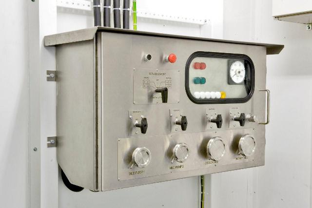
Every Drilling Rig must have a Power Control Room – sometimes also known as an SCR (standing for Silicon Controlled Rectifier) System – which forms the functional heart of the power control of the drilling operations. Typically, SCR systems comprise a large steel room, inside of which will be a range of Motor Control Centres, Engine & Generator Controls, SCR Control cubicles, and other instruments and systems used for drilling purposes.
SCR Systems usually operate at 600V, and clearly, these systems can be extremely dangerous if not operated correctly and carefully by suitably trained operators. It is therefore vital that drilling engineers and operators are well trained using a combination of class room tuition and on-the-job training.
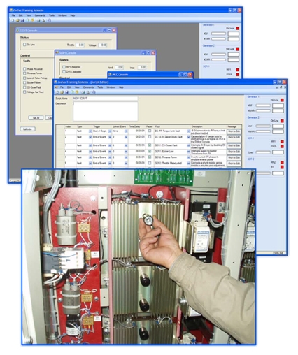
In response to this need, Zeefax have created the world’s first full size SCR Training Simulator, which accurately mimics the a real SCR; it looks and feels like the real thing, providing a realistic experience of live field operations – but without the dangerous high voltage. This system was created specifically for Naftogaz – for more details, click here.
A key feature of the simulator is the addition of the on-board computer system, which mimics all of the signals that would normally come into this SCR system from the live engines and generators, including the motors running the mud pumps, the rotary table or the Drawworks, etc. and can also simulate a wide range of known faults, allowing trainees to experience first hand problem solving in the safety of the simulator, before they experience the live system.GE Legacy Drive Systems
Used the same type SCR bridge as the Generation III, but rated at only 1200-1500 amp since the heat sink assembly is of a slightly different design. This system uses the GE generator GEM modules controls.
1980’s, 900amp. SCR bridges using the GE GEM Generator Control. As the bridges are small it requires two SCR bays to run a two-motor Mud Pump or Drawworks.
If you are interested in applying for this position, then please send us your latest CV and a covering letter toTest and Calibration Engineer – SCR products
Zeefax is the value source for parts and services for your legacy GE Drive and Generator Control Systems. We hold an inventory of critical spare parts and can provide comprehensive service solutions including Repair and Return of Modules and PCBs.
Zeefax operates a comprehensive repair and return service for all legacy GE Drive and Generator Control Systems. which includes cleaning, testing, repairing or replacement of defective components and a full system load test. This service includes a 6-month limited warranty.
Zeefax understands that replacement of a complete SCR Control System is often not viable due to the large cost and loss of production due to system downtime. At Zeefax we can offer a comprehensive service to support your legacy GE Drives and give it a renewed lease of life. That not only includes supply of spare parts and a repair/calibration service; qualified service engineers with years of experience with these Drives are available for regular Health Checks, fault-finding and general support purposes.Careers
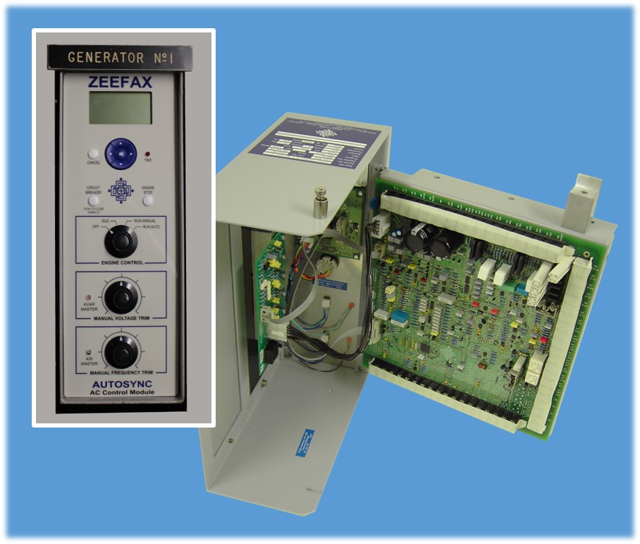
In response to many customer requests, we have designed our own version of the legacy Ross Hill Controls AutoSync AC generator control module; the new module has been completely re-designed and incorporates all new digital circuitry as well as optional expansion capability to future proof the module.
Advancements in technology mean that many of the power semiconductors which were built into SCR systems 30 or more years ago have been superseded by new devices, often with improved specifications.
Our engineers are able to ensure that, when the original component is not available, a suitable replacement can be found. If the replacement is not an exact fit, we can engineer an adaptation to ensure continued serviceability of legacy equipment.Hill Graham Controls (HGC)
Following our acquisition of Hill Graham Controls (HGC), Zeefaxis in a unique position to offer total support for all legacy Hill Graham and Ross Hill Controls (RHC) systems both in the UK and throughout the world.
Zeefax’s unique experience and expertise has allowed the company to design, manufacture, supply, repair and calibrate many of the control modules used within older Hill Graham installations, as well as other manufacturer’s systems, including Ross Hill Controls (RHC) type systems.
In recent times,Zeefax has developed and brought to market a new digital AutoSync module, with an improved contemporary design and operation. This advanced module occupies the exact same footprint and has pin-for-pin connection compatibility with the now obsolete Ross Hill module, thereby providing a simple and cost effective upgrade path for existing users of the AutoSync module.
As part of our maintenance and service offerings for SCR systems, Zeefax is able to mobilise support and engineers to provide technical assistance during emergency shutdowns and downtime periods.
Given our years of experience and unique position to offer total support for all legacy Hill Graham Controls (HGC), and other manufacturer’s systems including Ross Hill Controls (RHC), IPS, and GE Micro Drill SCR systems, Zeefax can provide a full range of technical services for installation, commissioning, and ongoing operational support.SCR System Health Checks
The time to find out if your system is reliable is when operations are quiet – not during critical well operations – so the Zeefax SCR System Health Check is designed to identify potential weaknesses and either repair or replace immediately, or mitigate against these until a repair or replacement can be effected – usually at a quite time.
For reliable operation, the contact between the SCR devices and the heatsinks must be as good as possible but over time, and especially in offshore installations, corrosion may attack the interface between the SCR device plating and the aluminium heatsink. If corrosion is present it takes an expert to decide if refurbishment is required because as long as the damage is minimal and the two elements remain undisturbed, the mutual corrosion may still maintain a good contact.
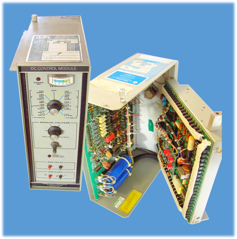
Since our acquisition of Hill Graham Controls (HGC), our module repair facility and engineers, have been able to test and calibrate modules sent to us for repair within a quick turnaround period. In an important development, Zeefax has designed and built a new AC and DC Module simulator, to provide an improved testing platform for Hill Graham and Ross Hill type AC and DC modules. In particular, the AC module simulator is much improved over the older unit, and provides a greatly enhanced engine control and start-up simulation.
In addition, we are able to repair and re-calibrate most Hill Graham and Ross Hill type printed circuit boards (PCBs), including Power Limit, Field Supply Regulator, Sprocket Slip, Drillers Console, DC Auxiliary, SCR Auxiliary and Generator Exciter PCBs. Furthermore if following evaluation, repair is not possible, in many cases we can supply new manufactured boards using the original designs, but enhanced by us using modern components and manufacturing techniques. In this way, we can help to ensure that legacy systems remain operational and continue to provide reliable and trouble free service beyond their expected life.Motors & Generators
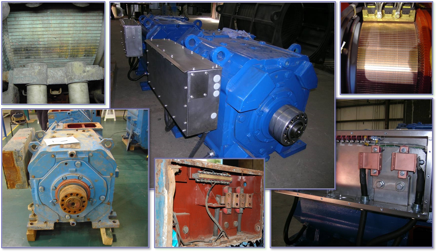
Even given the relatively controlled working environment of typical SCR pods, the conditions can often cause deterioration to both electrical and mechanical performance, requiring removal of the unit from the system, followed by refurbishment and renovation.
The heat sinks are inspected and if required, will be re-machined to ensure excellent electrical contact is maintained. Importantly, the SCR Thyristor ‘puck’ is replaced, and very special attention is given to the clamping torque and orientation.
If you would like to know more about the range of available Driller’s Foot Throttles, please call or email us, and we will be pleased to assist.SCR Blower Assemblies
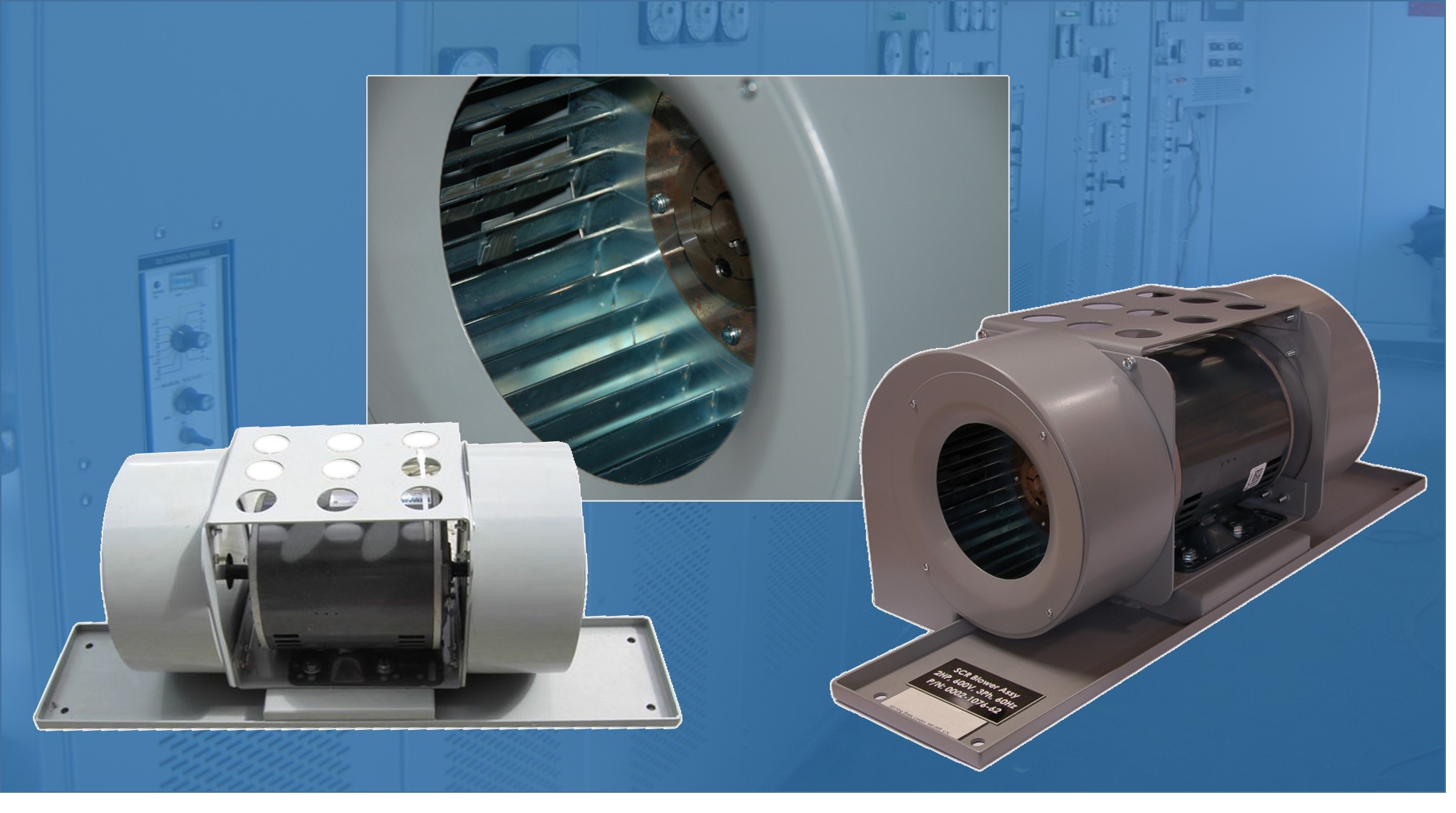
An important part of every system is the forced air cooling, which is vital to ensure continuity and reliability of operation of the SCR stacks. It is essential that the heat generated during operation is reliably carried away, and Zeefax now produce a series of SCR Blower Assemblies which are compatible with the those used in legacy Hill Graham and Ross Hill type systems.
The Zeefax SCR Blowers are designed to operate with voltages up to 600 V @ 50 or 60 Hz; the operating voltage needs to be specified at the time of purchase (see the details and specification form below) and the blower may be configured with either Single or Duplex impellers and with or without base frames.
In order to aid potential users with the selection of replacement blowers, we have created a simple form which can be used to provide the few technical details we require. In this way, we can ensure that any SCR Blower supplied by us is fully compatible with existing assemblies, and will then install directly into the available location with minimal re-work required. You can download this form from this site; please fill it in and return it to us to receive a quotation.
Through our in-house R&D, we are developing improved specification products as replacements for legacy Hill Graham Controls or Ross Hill Controls boards; we can provide original replacements for many of the PCBs used on these systems, and by using modern techniques and components, we can even improve on some of the design features of the original products to enhance reliability and functionality.
SIMOTION DRIVE-BASED CONTROLLER EXTENSION CX32; INVERTER CONTROL MODULE; TO INCREASEDRIVE COUNT ON SIMOTION D4X5; INTERFACES: 4 DI, 4 DI/DO, 4 DRIVE-CLIQ6SL3040-0NA00-0AA0
SINAMICS/MICROMASTER PX LC-MOTOR FILTER FOR 3-PH 380-480 V, 50/60 HZ, 210 A AND 3-PH 380-480 V, 50/60 HZ, 260 A AC DRIVES/POWER MODULES/ MOTOR MODULES6SL3000-2CE32-3AA0
SINAMICS S120 SINGLE MOTOR MODULE INPUT: DC 600V OUTPUT: 3AC 400V, 200A OUTPUT: AT8 KHZ / 140A FRAME SIZE: BOOKSIZE INTERNAL AIR COOLING OPTIMIZED PULSE SAMPLE AND SUPPORT OF THE EXTENDED SAFETY INTEGRATED FUNCTIONS INCL. DRIVE-CLIQ CABLE6SL3120-1TE32-0AA4
SINAMICS S120 SMART LINE MODULE INPUT: 3 AC 380-480 V, 50/60HZ OUTPUT: 600 V DC, 17 A, 10 KW FRAME SIZE: BOOKSIZE EXTERNAL AIR COOLING INCL. CONTROL VOLTAGE ADAPTER AND DRIVE-CLIQ CABLE6SL3131-6AE21-0AA0
SINAMICS / SIMODRIVE 611 BASIC LINE FILTER FOR 16KW ACTIVE LINE MODULE AND 16KW SMART LINE MODULE INPUT: 3AC 380-480V, 50/60HZ PLEASE OBSERVE CONDITIONS OF USE!6SL3000-0BE21-6DA0
SINAMICS / SIMODRIVE 611 BASIC LINE FILTER FOR 55KW ACTIVE LINE MODULE INPUT: 3AC 380-480V, 50/60HZ PLEASE OBSERVE CONDITIONS OF USE!6SL3000-0BE25-5DA0
SINAMICS / SIMODRIVE611 HFD LINE REACTOR WITH CONNECTORS FOR 80 KW ACTIVE LINE MODULE INPUT: 3AC 380-480 V, 50/60 HZ FOR FUNCTION DUMPINGRESISTOR ADDITIVE NECESSARY!6SL3000-0DE28-0AA1
SINAMICS / SIMODRIVE- SUBASSEMBLY WITH ELECTRICAL FILTER FUNCTION SINAMICS LINE FILTER AND HF LINE PACKAGE FOR 5 KW SMART LINE MODULE INPUT: 3-PH 380-480 V, 50/60 HZ CONTAINS: LINE FILTER TYPE 3000-0HE15-0AA0 AND HF LINE REACTOR TYPE 6SL3000-0CE15-0AA06SL3000-0GE15-0AA0
SINAMICS / SIMODRIVE- SUBASSEMBLY WITH ELECTRICAL FILTER FUNCTION SINAMICS LINE FILTER AND HF LINE PACKAGE FOR 10 KW SMART LINE MODULE INPUT: 3-PH 380-480 V, 50/60 HZ CONTAINS: LINE FILTER TYPE 3000-0HE21-0AA0 AND HF LINE REACTOR TYPE 6SL3000-0CE21-0AA06SL3000-0GE21-0AA0
SINAMICS TERMINAL MODULE CABINET TM31 WITHOUT DRIVE-CLIQ CABLE ADD ON BOARD FOR SINAMICS CONVERTORS WITH DIGITAL AND ANALOG IN- AND OUTPUTS6SL3055-0AA00-3AA1
SINAMICS S120 TERMINAL MODULE CABINET TM54F WITHOUT DRIVE-CLIQ CABLE ADD ON BOARD FOR SINAMICS CONVERTORS WITH FAIL-SAFE IN- AND OUTPUTS6SL3055-0AA00-3BA0
SIMOTION / SINAMICS S120 TERMINAL MODULE CABINET TM41 WITHOUT DRIVE-CLIQ CABLE ADD ON BOARD FOR SINAMICS CONVERTORS WITH DIGITAL AND ANALOG IN- AND OUTPUTS PLUS INCREMENTAL ENCODER SIMULATION6SL3055-0AA00-3PA1
SINAMICS S120 SENSOR MODULE SMC20 BOARD FOR EVALUATION OF INCREMENTAL ENCODER: SIN/COS 1VPP ABSOLUTE ENCODER: ENDAT WITHOUT DRIVE-CLIQ CABLE 30 MM WIDTH6SL3055-0AA00-5BA3
SINAMICS SENSOR MODULE SMC30 FOR INCREMENTAL ENCODER: TTL/HTL OR KOMBI ENCODER SSI WITH INCREMENTAL TRACES OR KOMBI ENCODER SSI WITHOUT INCREMENTAL SIGNALS / WITHOUT DRIVE-CLIQ CABLE 30 MM WIDTH6SL3055-0AA00-5CA2
SINAMICS TERMINAL MODULE CABINET TM120 WITHOUT DRIVE-CLIQ CABLE ADD ON BOARD FOR SINAMICS CONVERTERS PTC- AND KTY-ANALOG INPUTS WITH SAFE ELECTRICAL ISOLATION6SL3055-0AA00-3KA0
SINAMICS SENSOR MODULE SME120 INCREMENTAL ENCODER: SIN/COS 1VPP; PTC- AND KTY-INPUTS WITH SET; DEGREE OF PROTECTION IP67; WITHOUT DRIVE-CLIQ CABLE6SL3055-0AA00-5JA3
SINAMICS SENSOR MODULE SME125 ABSOLUTE ENCODER: ENDAT; PTC- AND KTY-INPUTS WITH SET; DEGREE OF PROTECTION IP67; WITHOUT DRIVE-CLIQ CABLE6SL3055-0AA00-5KA3
SINAMICS / SIMODRIVE- ELECTRONIC POWER CONVERTER STARTER PACKAGE S110; 220V IN ADDITION THE MOTOR 1FK7022-5AK21-1UA0 MUST BE ORDERED IN A SEPARATE POSITION SAP. PLEASE ALSO ADD THE FOLLOW TEXT AS THE SAP OFFER NUMBER: “STARTER PACKAGE S110; 220V” G-PRICES FOR BOTH POSITIONS ARE AUTOMATICALLY CALCULATED. THE K-PRICE FOR THE PACKAGE MUST BE TYPED IN MANUALLY6SL3076-0AB00-0AA0
Rigs used for wellbore operations, both land based and offshore, use a wide variety of tools, apparatuses, appliances, systems and devices that use electrical power. Typically power is supplied by one or more generators that run on diesel fuel or other hydrocarbon fuel. Such rigs, including, but not limited to, drilling rigs and production platforms, have for example, drawworks, pumps, motors mud pumps, drive system(s) (rotary, power swivel, top drive), pipe racking systems, hydraulic power units, and/or a variety of rig utilities (lights, A/C units, appliances), electronics, and control systems for these things. Typical conventional drilling rigs have one or more alternating current (AC) power generators which provide power to silicon controlled rectifier(s) which convert the AC power to DC power, e.g. for DC motors of various tools and systems, and for DC-powered top drives or prime movers.
In certain aspects, in a distributed power system according to the present invention, each tool, etc. in the system determines how much power is available and how much power other tools, etc. on the system are consuming. For example, on a drilling rig there is a Drawworks, Top Drive, Mud Pumps, and 3 generators, the Drawworks having three 1150 horsepower motors, the Top Drive having one 1150 horsepower motor, and the Mud Pump having two 1150 horsepower motors. Each generator can produce one Megawatt (MW) of power; so, with all generators running, 3 MW of power are available. Some of this power is being used by other services and utilities (lights, office areas, appliances, etc.) so not all of this power is available for the drill floor tools. In one aspect, it is not important for the tools, etc. to know where the power is being used, but it the tools are able to determine the maximum power capacity (the total number of generators on-line times the maximum capacity for each generator) and how much power is actually being consumed. The difference between the total power capacity and the actual consumption is the unused or available capacity.
When the rotation of the rotatable drum is in a hoisting direction or is stationary, the drawworks control system provides a disabling signal for commencing a gradual release of the brake arrangement from the rotatable drum. When the rotation of the rotatable drum is in a lowering direction, the drawworks control system provides an enabling signal for engaging the brake arrangement to limit rotation of the rotatable drum. The reverse rotation of the drum or of the drawworks motor produces power. This power is converted into electrical power by a drive and this electrical power is fed to a motor (or motors) which is run continuously to supply power as needed on the rig. In one aspect this power accelerates a high speed motor to a much higher speed than base free-wheeling speed.
Accordingly, the present invention includes features and advantages which are believed to enable it to advance rig power reclamation technology. Characteristics and advantages of the present invention described above and additional features and benefits will be readily apparent to those skilled in the art upon consideration of the following detailed description of preferred embodiments and referring to the accompanying drawings.
Certain embodiments of this invention are not limited to any particular individual feature disclosed here, but include combinations of them distinguished from the prior art in their structures, functions, and/or results achieved. Features of the invention have been broadly described so that the detailed descriptions that follow may be better understood, and in order that the contributions of this invention to the arts may be better appreciated. There are, of course, additional aspects of the invention described below and which may be included in the subject matter of this invention. Those skilled in the art who have the benefit of this invention, its teachings, and suggestions will appreciate that the conceptions of this disclosure may be used as a creative basis for designing other structures, methods and systems for carrying out and practicing the present invention. This invention includes any legally equivalent devices or methods which do not depart from the spirit and scope of the present invention.
The present invention recognizes and addresses the problems and needs in this area and provides a solution to those problems and a satisfactory meeting of those needs in its various possible embodiments and equivalents thereof. To one of skill in this art who has the benefits of this invention"s realizations, teachings, disclosures, and suggestions, other purposes and advantages will be appreciated from the following description of certain preferred embodiments, given for the purpose of disclosure, when taken in conjunction with the accompanying drawings. The detail in these descriptions is not intended to thwart this patent"s object to claim this invention no matter how others may later attempt to disguise it by variations in form, changes, or additions of further improvements.
It will be understood that the various embodiments of the present invention may include one, some, or all of the disclosed, described, and/or enumerated improvements and/or technical advantages and/or elements in claims to this invention. BRIEF DESCRIPTION OF THE DRAWINGS
A more particular description of embodiments of the invention briefly summarized above may be had by references to the embodiments which are shown in the drawings which form a part of this specification. These drawings illustrate certain preferred embodiments and are not to be used to improperly limit the scope of the invention which may have other equally effective or legally equivalent embodiments.
Presently preferred embodiments of the invention are shown in the above-identified figures and described in detail below. It should be understood that the appended drawings and description herein are of preferred embodiments and are not intended to limit the invention or the appended claims. On the contrary, the intention is to cover all modifications, equivalents and alternatives falling within the spirit and scope of the invention as defined by the appended claims. In showing and describing the preferred embodiments, like or identical reference numerals are used to identify common or similar elements. The figures are not necessarily to scale and certain features and certain views of the figures may be shown exaggerated in scale or in schematic in the interest of clarity and conciseness.
As used herein and throughout all the various portions (and headings) herein, the terms “invention”, “present invention” and variations thereof mean one or more embodiment, and are not intended to mean the claimed invention of any particular appended claim(s) or all of the appended claims. Accordingly, the subject or topic of each such reference is not automatically or necessarily part of, or required by, any particular claim(s) merely because of such reference. So long as they are not mutually exclusive or contradictory any aspect or feature or combination of aspects or features of any embodiment disclosed herein may be used in any other embodiment disclosed herein. DETAILED DESCRIPTION OF THE INVENTION
A hoisting line 30 is securely fixed at one end to ground by means of a dead line 35 and a dead line anchor 40. The other end of the hoisting line 30 forms a fast line 45 attached to drawworks 50. The drawworks 50 includes one or more electrical motors 55 and a transmission 60 connected to a cylindrical rotatable drum 65 for wrapping and unwrapping the fast line 45 as required for operation of the associated crown block 15 and traveling block 20. The rotatable drum 65 is also referred to as a winding drum or a hoisting drum. A brake arrangement 70 includes a primary friction brake 80, typically a band type brake or disk brake, an auxiliary brake 75, such as an eddy current type brake or a magnetic brake, and an emergency brake 78. The brake arrangement 70 is connected to the drawworks 50 by driveshaft 85 of the drawworks 50. The brake arrangement 70 is typically actuated either hydraulically or pneumatically, using, for example, a pneumatic cylinder that is engaged by rig air pressure by way of an electronically actuated air valve.
A measuring device, such as an encoder 22, for example, is affixed to the driveshaft 85. An electrical output signal representative of the rotation of the rotatable drum 65 is produced on line 24 from encoder 22 as drum 65 rotates to pay out or wind up fast line 45 as the traveling block 20 descends or rises. The frequency of the encoder is used to measure the velocity of the traveling block 20 movement, typically, by calculating the actual drum 65 speed and ultimately the traveling block 20 speed based on lines strung, the diameter of the drum 65, the number of line wraps and the line size. Alternatively, the velocity of the traveling block 20 movement is calculated from the change in the vertical position of the traveling block 20.
A drawworks control system 42 receives electrical output signals from the proximity switches 26, the encoder 22 and the strain gage 89, and is connected to the brake arrangement 70. The drawworks control system 42 is connected to a driller or operator control center 44 located on or near the derrick 11. The drawworks control system 42 is also connected to the electrical motor 55 through a drive 46. The drawworks motor 55 is an alternating current (AC) motor or a direct current (DC) motor and the drive 46 is an AC or a DC drive respectively. The drive 46, for example, includes a controller 48, such as a programmable logic controller (PLC) and one or more power electronic switches 52 connected to an AC bus 54. For example, the drive for a DC motor includes an electronic switch 52 such as a silicon controlled rectifier for AC/DC conversion.
The drawworks control system 42 can include a programmable logic controller (the drawworks PLC 156) and is interfaced with the drive 46 using, for example, a serial communication connection 58 such as, for example, an optical linkage and/or hard-wired linkage. Two or more remote programmable logic controller (PLC) input/output (I/O) units 62 are used to control the transmission 60 and brake arrangement 70 of the drawworks 50. Alternatively, a processor 64 is also connected to the drawworks control system 53 for providing operating parameters and calculated values during the performance of various drilling rig operations. The processor 64 is a conventional signal processor, such as a general-purpose digital computer.
The drawworks control system 42 provides a velocity command and a torque command signal to the drive controller 46. The drive 46 uses regeneration when necessary to maintain the velocity considering power system limit requirements. Each drive 46 provides the motor velocity (with a signed integer to indicate the direction of movement) and the torque level (with a signed integer to indicate the direction of movement) feedback to the drawworks control system 42. The drive controller 48 also provides flags to the drawworks control system 42 to indicate various alarm conditions of the drive 46 and the motor 55.
An operator control center 44 or man-machine interface is, in certain aspects, a console including throttle control joysticks, switches, and an industrial processor driven monitor 69 wherein the operator or driller can set and control certain operational parameters. For example, the operator controls the direction and velocity of the traveling block 20 movement using a movement control joystick 71 installed at the operator console. The travel of the movement control joystick 71 produces a linear analog electrical input signal provided to the drawworks PLC 56 of the drawworks control system 42.
Through the use of various switches and/or levers at the operator control center 44, the operator selects operational parameters, such as, for example, a gear selection switch 83, an override switch 85 and an emergency shutoff switch 87. Alternatively, the monitor is, for example, a typical industrial computer including a touch-screen monitor mounted in front of the operator as a part of the man-machine interface. The operator monitors and sets system parameters and operational parameters including; the number of active drives, the active gear selected, the traveling block position, the block speed, the hook load, the upper and lower position set points, the maximum traveling block velocity set point, the percentage of control disk brake applied, the parked condition, and any abnormal or alarm condition flags or messages. The operator can modify the upper and lower traveling block position set points, the maximum traveling block velocity set points and acknowledge certain alarms.
For hoisting the traveling block 20, the operator, for example, sets the movement control joystick in the hoisting position and the traveling block 20 and any associated equipment or suspended load accelerates upward until the traveling block reaches and maintains the velocity set by the position of the joystick set by the operator. For lowering the traveling block 20, the operator, for example, sets the movement control joystick in the lowering position and the traveling block 20 and any associated equipment or suspended load accelerates downward (driven by the electrical motor 55, if required) to reach and maintain the velocity set by the position of the movement control joystick.
In the system of the present invention, regenerative or dynamic braking of the one or more electric motors 55, controlled by the drive 120, can be used as the primary method of braking during all modes of movement and velocity control, and stopping of the traveling block 20. The drawworks control system 42 provides a velocity command signal to the drive 46 for hoisting, lowering and stopping, and the drive 46 maintains the velocity according to the velocity command signal provided using regeneration or dynamic braking when necessary. The friction brake 80 is used to back up or compliment this retarding force of regeneration and to hold the traveling block 20 and load in the parking mode.
The high-speed motor 90 can be used to run rig apparatuses and devices, e.g. the drawworks motors, and items AA, BB, and CC, shown schematically (indicated by dash-dot lines) which may be, but are not limited to, pumps motors, rotaries, top drives, racking systems, and HPU"s.
Referring now to FIG. 3A, a system according to the present invention has a drilling rig 41 depicted schematically as a land rig, but other rigs (e.g., offshore rigs and platforms, jack-up rigs, semi-submersibles, drill ships, and the like) are within the scope of the present invention. In conjunction with an operator interface, e.g. an interface 320, a control system 360 controls operations of the rig. The rig 411 includes a derrick 413 that is supported on the ground above a rig floor 415. The rig 411 includes lifting apparatus, a crown block 417 mounted to derrick 413 and a traveling block 419 interconnected by a cable 421 that is driven by a drawworks 423 (with an electrically powered motor or motors) to control the upward and downward movement of the traveling block 419. Traveling block 419 carries a hook 425 from which is suspended a top drive system 427 which includes a variable frequency drive controller 426, a motor (or motors) 424, electrically powered, and a drive shaft 429. A power swivel may be used instead of a top drive. The top drive system 427 rotates a drillstring 431 to which the drive shaft 429 is connected in a wellbore 433. The top drive system 427 can be operated to rotate the drillstring 431 in either direction. According to an embodiment of the present invention, the drillstring 431 is coupled to the top drive system 427 through an instrumented sub 439 which includes sensors that provide drilling parameter information.
The drillstring 431 may be any typical drillstring and, in one aspect, includes a plurality of interconnected sections of drill pipe 435 a bottom hole assembly (BHA) 437, which can include stabilizers, drill collars, and/or an apparatus or device, in one aspect, a suite of measurement while drilling (MWD) instruments including a steering tool 451 to provide bit face angle information. Optionally a bent sub 441 is used with a downhole or mud motor 442 and a bit 456, connected to the BHA 437. As is well known, the face angle of the bit 456 can be controlled in azimuth and pitch during drilling.
Drilling fluid is delivered to the drillstring 431 by mud pumps 443 which have electrically-powered motors through a mud hose 445. The drillstring 431 is rotated within bore hole 433 by the top drive system 427. During sliding drilling, the drillstring 431 is held in place by top drive system 427 while the bit 456 is rotated by the mud motor 142, which is supplied with drilling fluid by the mud pumps 443. The driller can operate top drive system 427 to change the face angle of the bit 456. The cuttings produced as the bit drills into the earth are carried out of bore hole 433 by drilling mud supplied by the mud pumps 443.
Rig utilities are shown collectively and schematically as the block 465. A power system 470 with generators 472 (and associated rectifiers as needed) provides power to the various power-consuming items on the rig (as shown by dotted lines). Each of the items 423, 427, 443 and 460 has its own single board computer 423 c, 427 c, 443 cand 460 crespectively. Although a top drive rig is illustrated, it is, optionally, within the scope of the present invention, for the present invention to be used in connection with a rotary system 460 in which a rotary table and kelly are used to rotate the drillstring (or with a rotary system above).
FIGS. 5A-5C show an adaptive allocation of power according to the present invention to several power consuming entities on a rig at initial power levels and when the total available power decreases. FIG. 5A illustrates graphically a power limit and actual power usage for a drawworks, mud pumps, and rig utilities. In this situation there are five generators, each able to produce 1 Megawatt of power. A static power allocation for the rig utilities is assumed to be 500 kilowatts. 1 Megawatt is being used by the mud pumps. The drawworks is, initially, using 2 Megawatts.
Megawatts can be generated (see FIG. 5C). At this point, this moment, the total rig power consumption is 4.5 MW (See FIG. 5B) (consumption of power by drawworks, mud pumps, rig utilities). The single board computer of the drawworks sees a 0.5 Megawatt deficit. This drawworks single board computer immediately attempts to compensate for the entire 0.5 Megawatt deficit by itself. It knows the drawworks is presently using 2.5 Megawatts, but this level is instantaneously lowered by the drawworks single board computer (in response to the power deficit indication) and the single board computer re-sets the drawworks power limit to 2 Megawatts. At this point the drawworks control system only allows the drawworks to use 2.0 Megawatts of power.
In another example a drilling rig has a Drawworks, a Top Drive System, a Mud Pump System with multiple Mud Pumps, and three generators. The drawworks has three 1150 horsepower motors, the Top Drive has one 1150 horsepower motor, and the Mud Pump has two 1150 horsepower motors—all motors electrically powered. Each generator can produce one Megawatt (MW) of power, so, with all generators running, a maximum of 3 MW of power are available.
With all three generators on line and at that moment producing 300 kW of power each, the total available capacity is 3 MW (3.times.300 kW)=2.1 MW. The Mud Pumps are running and using 100 kW of power; and thus the single board computer for the Mud Pumps sets an internal power limit to 2.1 MW+100 kW=2.2 MW; but, since the maximum allowed horsepower is 2300 horsepower, it uses a limit of 1.7 kW. The Top Drive is using 300 kW of power, and its single board computer determines a maximum power limit of 2.1 MW+300 kW=2.4 MW; but since the maximum allowed power for the Top Drive is 1150 horsepower or 858 kW it sets its internal power limit to 858 kW. Similarly, with the Drawworks consuming 300 kW of power, it sets its power limit to 2.1 MW+300 kW=2.4 MW. Since its maximum allowed horsepower is 3450 horsepower (2.57 MW), it uses 2.4 kW for its power limit.
In both of the cases described above the total power limits for all the tools are greater than the actual capacity of the generators. This is a “greedy” approach that allows each tool to assume the entire reserve capacity could be allocated to it. In reality this is effective since the power outputs are dynamically updated values (updated, e.g., fifty times a second) and as one tool or entity starts to use more power the other tools power budgets are reduced because the total available power is reduced.
There may be a lag between how rapidly a tool can start consuming power and how quickly other tools reduce their total power available calculation. Since only, typically, a Top Drive and Drawworks generally have sudden increases in power consumption, and in real rig applications they do not usually consume large amounts of power simultaneously, such a lag is not a problem. The Drawworks is a large consumer of power while hoisting rapidly when the Top Drive is, or should be, idle and the Top Drive is a large consumer of power while drilling ahead while the Drawworks is lowering very slowly and actually regenerating power. If it turns out that the power data has sufficient lag that allowing each tool to greedily allocate all reserve power to itself causes overpower conditions. It would be possible to add a power preference factor to each tool for the percentage of available power it will allocate to itself. In one such case, power limit calculations for the first example described above would be:
If the “greedy” approach fails, in another method according to the present invention each tool calculates the actual power usage by each of the other tools (and itself), and allocates the remaining power budget accordingly. This provides a response to any change in the power condition perfectly, but each tool must be reading information, e.g. speed/torque feedbacks, from every tool system, and apparatus on the network. Once each tool has established its power limit, it safely sets the internal speed and torque limits of its motor to operate within the power limit and remain safe. For tools with electrically powered motors, each tool calculates a speed and torque limit based on its static logic and operator requests. The tool"s single board computer"s software handles the case where the drive is not moving as fast as requested, a result of power limiting. The electrical power consumption of a given motor can be calculated by the current speed and torque outputs:
The controller takes a snap-shot of the tools actual speed and consumer power is being reduced. This “locked downward ratcheted speed reference” occurs very fast in a quasi-hyperbolic fashion while approaching the available-power/consumed-power equilibrium asymptote. The locked ratcheted speed reference is applied to the drive when the power equation is satisfied.
In certain aspects, embodiments of the present invention use a motor as a flywheel apparatus. In one aspect an “inside out” AC permanent magnet motor rotor acts as the flywheel (or multiple motors are used). In one aspect such a motor, is a motor 900 as shown in FIG. 9, with a rotor/flywheel 903 which is a hollow cylinder constructed, e.g. of steel or aluminum, with permanent magnets 904, e.g. rare earth magnets, attached to the inner surface. A stator 905 is concentrically located within the rotor, fixed to a stationary hollow shaft 902, so that the rotor revolves around the stator/shaft assembly on a roller bearings 901. 3-phase cables 907 and optional cooling channels 908 are brought out through the stationary shaft. Speed feedback is externally provided to a Variable Frequency Drive (“VFD”) via an absolute position encoder 906. The VFD provides power back to the motor 900 and can exchange power with a power source “PS” (utility, batteries, and/or generators). Without limitation and by way of example, motors as disclosed in U.S. application Ser. No. 11/789,040 filed Apr. 23, 2007 and U.S. application Ser. No. 11/709,940 filed Feb. 22, 2007 (both co-owned with the present invention and incorporated fully herein for all purposes) may be used.
FIG. 6 shows a system 600 according to the present invention which has a plurality of rig power generators GS each with its own engine E for providing power to run the generators GS. Power from the generators GS runs multiple drawworks D. Optionally a separate utility entity U can supply power to run the generators GS and/or, optionally, such power can be supplied by a battery bank B. One, two, three or more flywheel apparatuses F (two shown) store power generated when a load is being lowered by the drawworks D and provide power as needed to run the drawworks D. Each flywheel apparatus has a drive components C and V, e.g. a fully regenerative converter and variable frequency inverter which form a complete VFD “variable frequency drive”. Optionally one or more resistor banks R (two shown) may be used for voltage control, each with a corresponding DC/DC converter or “chopper” T. A programmable logic controller PLC (or other suitable control system) controls the system 600.
When, in systems as the system 600, drawworks traction drives and motors impose a large volt amp reactive (“VAR”) demand on the power system, the PLC participates in the regulation of VARs. In this system, magnetizing VARs for the drawworks motors are supplied by the regenerative drive components C during low speed, high torque situations. The PLC regulates the rate VAR"s is injected onto the main AC bus M. This prevents the rig generators GS from reaching VAR limits prematurely while also reducing the torque demand from the engines E during block loading.
Since improved engine throttle response is one of intended outcomes of this system, bus frequency and voltage are monitored by sensors O for pre-determined variations. Corrective action is applied by the PLC by injection of real and/or reactive power according to the degree that either bus frequency or voltage deviate from the pre-determined values. Bus frequency feedback along with upward block speed are used by the PLC to determine the rate at which power from the flywheels F is injected onto the main bus M. Silican controlled rectifier drives, SCR, control output power and speed of the drawworks DC traction motors.
FIG. 7 shows a system 700 according to the present invention with some parts and components like those of the system 600 (and like parts and components have the same identifiers in FIG. 6 and FIG. 7). The drive components C in the system of FIG. 6 are not needed in the system of FIG. 7 which uses AC-powered motors for its drawworks K. In the system 700, power is exchanged between flywheel inverters N and drawworks inverters W across the DC bus. VARs are supplied directly to the AC motors of the drawworks from the drawworks inverters W so VAR injection on an AC bus 702 is not required. Systems with a DC drawworks manage both kW and kVAR injection at a main AC bus (FIG. 6). As with the case of a DC drawworks, control of the flywheels F is based on power demand, available power, and exhaust temperatures of the engines E. As is the case with DC drawworks, energy to overcome mechanical losses and drive inefficiencies is supplied from external sources including, but not limited to, the generators GS, utilities U, or battery banks B.
The present invention, therefore, provides in at least certain embodiments, a system for controlling power load to a rig engine of a wellbore rig, the system including a controller for controlling a rig engine; a sensor for sensing the exhaust temperature of a rig engine, the sensor in communication with the controller for providing to the controller signals indicative of the exhaust temperature; and the controller maintaining power load to the rig engine based on said exhaust temperature. Such a screen may have one or some, in any possible combination, of the following: wherein the rig engine has a rated capacity (e.g. in kilowatts) and wherein the controller provides a sufficient power load to the rig engine to maintain the rig engine in operation at least seventy percent of the engine rated capacity; wherein the rig engine is a natural gas powered engine; flywheel apparatus for storing generated power for powering the rig engine, and the controller controlling the flywheel apparatus; wherein the flywheel apparatus is an inside-out AC motor; wherein power is applied to the flywheel apparatus, the system includes drawworks apparatus, said power generated by braking of the drawworks apparatus; wherein the drawworks apparatus used to move a travelling block of the rig and a peak output of the flywheel apparatus is at least equal to potential energy of the travelling block; wherein the drawworks apparatus is powered by an inside-out AC permanent magnet motor; wherein said peak output is greater than said potential energy; rig generator apparatus for generating power to operate a drawworks system; the controller for controlling the rig generator apparatus; wherein the controller controls power charging and power discharging of the flywheel apparatus so that average power from the rig generator apparatus is relatively constant during operation of the drawworks system; power source for supplying power to the rig engine, the controller monitoring available power from the power source; wherein the power source is any of utility, battery, rig generator, and flywheel apparatus and the controller monitors power available from any utility power source, rig generator power source, battery power source, and flywheel apparatus power source; wherein the controller compares values for available power to travelling block speed and height and, based on these values, calculates potential energy of the block and controls power charging of any flywheel apparatus and battery; wherein there is a flywheel apparatus and the controller regulates power input to the flywheel apparatus with power output from the flywheel apparatus based on rig engine exhaust temperature, all available power, and desired power load to the rig engine; rig generator apparatus, the controller for preventing the rig generator apparatus from exceeding VAR limits; a main power bus for sharing available power, the controller for determining rate at which power from the flywheel apparatus is supplied to the main power bus to facilitate engine throttle response; wherein the rig engine supplies power for a well service rig, the system further including a utility power source, a rig generator power source, a battery power source, a flywheel apparatus for storing power generated by operation of a rig drawworks system, the controller for controlling power supplied to the rig engine; wherein the controller brings the rig generator on and off line to charge the battery power source and/or to operate the drawworks; wherein the controller controls the power sources so that the drawworks operates solely on power from only the battery power source; and/or wherein the controller is a programmable logic controller; and/or rig apparatuses, a plurality of rig generators for supplying power to the rig engine and to the rig apparatuses, the rig engine and each rig apparatus having a respective single board computer control, the controller for monitoring the plurality of rig generators to determine if a rig generator has failed, and each single board computer control taking into account a reduction in available power due to failure of a rig generator and each single board computer control reducing a power limit for its corresponding rig apparatus or rig engine.
What follows are some of the claims for some of the embodiments and aspects of the present invention, but these claims are not necessarily meant to be a complete listing of nor exhaustive of every possible aspect and embodiment of the invention. In the claims, means-plus-function clauses are intended to cover the structures described herein as performing the recited function and not only structural equivalents, but also equivalent structures. Thus, although a nail and a screw may not be structural equivalents in that a nail employs a cylindrical surface to secure wooden parts together, whereas a screw employs a helical surface, in the environment of fastening wooden parts, a nail and a screw may be equivalent structures. It is the express intention of the applicant not to invoke 35 U.S.C. .sctn.112, paragraph 6 for any limitations of any of the claims herein, except for those in which the claim expressly uses the words means for together with an associated function.
Whereas the present invention has been described in particular relation to the drawings attached hereto, it should be understood that other and further modifications apart from those shown or suggested herein, may be made within the scope and spirit of the present invention.
(3) National 400 JWS Triplex mud pumpw (4-1/2 and 5-1/2" Liners), p/b Detroit Series 60 diesel engine, 600 bbl capacity mud tanks with guns, agitators, hopper, Brandt King Cobra linear motion shale shaker, (2) 6x8 centrifugal mixing pumps p/b (2) 60 hp electric motors, 70 bbl mixing tank, 5000# 2" choke manifolds with 2 adjustable chokes
(2) Continental Emsco FB1600 triplex mud pumps rated at 1,600 HP (2000 input HP) Fully enclosed steel power end. New National Oilwell fluid ends FB 1600 5000 PSI.
Tanks: 8 ballast tank 13,399 bbls, potable water 1,150 bbls, fuel oil 1,525 bbls, pollution tank 96bbl, liquid mud 1,553 bbl, process tank 130 bbl, bulk tanks 1,300 cu.ft. drill water 4,892 bbl.
Rig and drawworks: Ideco Hydraulir H37 Model 308 “Ramber" single drum, 5 axle drive in carrier, Cat 3406E (550 hp) engines, Allison 5961 transmission, 103" x 212,000# telesc oping derrick with 1" drill line, max hook/load 168,000# on 6 lines and 112,000# on 4 lines, 37" x 10" forged steel brakes with water splash cooling
Gardner Denver PAH triplex pump (4-1/2 “ liners), p/b GM 8V71 diesel engine, 180 bbl mud tank, 180 bbl holding tank, centrifugal pump p/b Detrot 471 diesel engine with hopper (skidded)
GARDNER DENVER 1500E JACKUP RIG(REF#1288M) 1500 HP rig, manufactured 1978, drilling depth 15,000, National Oilwell Varco 350/500 top drive, model JU-45-MS (upgraded), Gardner Denver 1500E drawworks, 80" water depth capacity, 142" x 30" x 3" Lee C Moore Cantiliever mast 1,300,000#, (2) Gardner Denver PZ-10 Triplex mud pump powered by (2) EMD D-79 MB DC traction motors, 37.5" Oilwell rotary table, two speed transmission, powered by one EMD D-79 MB DC traction motor. Currently stacked in Louisiana. PRICE: $4,500,000
LIFTBOAT JACK UP VESSEL(Ref#1127M) Manufactured 1983, 79"L x 59"W x 8"H, open space 2800 sq ft, 192 GT, 150 NT, main deck carg o 105 (kips). (4) 148" x 42" legs (5/8" wall thickness braced), 22"L x 12"W x 24" depth pads (raked all sides), 70 ton crane with 80" boom, 10 ton aux crane with 50" boom. Main engines: (2) 12V71N GM (680SHP), 3:1:1 reduction gear (twin disc ratio), 8 knots. (2) Deep Well Pumps, (2) electric 400a welding machines, satelilite phone with internet, (2) 80kw Delco generators w/(2) 6V71N GM engines, 7500 gal fuel, 9800 gal potable water, navigation equipment, 28 berths (including boat crew), central A/C and heaters, Lounge w/Satellite TV, 4 heads, galley seats 16, laundry. Maximum working depth 90" (w/25" air gap), Max sea conditions: 4" hard, 5" soft bottom, 8-10 fpm speed. Working in USA Price: $5,700,000
JACK UP DRILLING/CORING RIG(Ref#9587) operates in 80" of water, composed of (6) 10" x 40" x 7"H FlexiFloats and (4) 10" x 20" x 7" H Flexifloats, (4) spuds, (4) 80" legs 3" dia x 40" long. Currently on the platform is a Gardner Denver mud rig used for drilling and core samples. Another type of rig such as a Mobile, Acker or CME could be placed on jack up. Currently working. Offered on rental basis: $40,000 per month. Will sellfor $1,100,000
0002-0390-12 1K 25W Dual potentiometer assembly ROSSHILL for mud pump0002-0390-12 1K 25W Dual potentiometer assembly ROSSHILL for mud pump0002-0390-12 1K 25W Dual potentiometer assembly ROSSHILL for mud pump
· Equipment Related to ADWOC Rig #1, (El MAGCO Brake 6032,) SCR System, Caterpillar, GE.(BASLER SCR Regulation), VARCO NOV TDS 11SA, Equipped With PLC Siemens , and IDM G5 VFD Control.
· Identifying parts, material, tools, documentation of any other job preparation requirements to maintain all kinds of rotating equipment. (CBM Compressors, Screw Compressors, (Air and Gas), Turbo Blowers, and Positive Displacement Blowers, and Pumps.
· Troubleshooting, servicing, maintaining, and equipment related to Well Heads, and Single Battery (Oil and Gas), pumps, compressors, and Gas Dehydration, Refrigeration components.
Power Generation, Troubleshooting, overhauling and maintaining EPPF (5MW), Run Chemical Injection Equipment Pumps and Compressors. For Wells (Oil and Gas)
· Troubleshooting, maintaining, servicing and overhauling equipment pertaining to Drilling Oil Rig and Auxiliaries, (El MAGCO Brake 6032, 7032) SCR Systems, Caterpillar, GE.(Hill Graham, Ross Hill) Drawworks, Rotary, and Mud Pumps, Centrifuge Pumps ( Solids Control SWACO)
MUD PUMPS - TRIPLEX - POWER END .................................................................................................................... 64


 8613371530291