
ross hill scr mud pump drive made in china

It is an unfortunate characteristic of SCR systems that the Power Factor (the relationship between real and reactive power) is poor – often down as low as 0.4 – which maeans that the KW capacity of the engines is under-utilised. This often leads to frustration because the rig runs out of power, yet the engines may be only delivering half of their full-load capacity. This article explains how the Power Limit system works and what can be done to ensure it is working at its optimal level.
In general terms, the KW the system consumes is provided by the engine. The other limitation on power delivery is the current capacity of the generator, which is often expressed as a VA or KVA value. SCR systems are designed with something like a 0.7 Power Factor rating; in other words, the KW of the engine will be 0.7 x the KVA rating of the generator. This goes some way to compensating for the poor Power Factor, but often is insufficient during operations where where the Mud Pumps are heavily loaded. However, measures are still available to ensure that the system is delivering what it can within these physical limitations, one one thing to ensure is that the Power Limit system is working optimally.
The purpose of the Power Limit is to prevent rig blackouts in the event of sudden increases in load. The original philosophy also was to allow the minimum number of engines to be run and maximise efficiency but most drilling operators prefer not to run up against these limits and demand as much power as is available. The Power Limit system measures the KW load of the highest loaded engine, and the current load of the highest loaded generator and compares this to a pre-set reference to determine if Power Limiting of the SCRs should occur. Furthermore, some systems have an initial 60% KW limit, which then opens up to 100% once this threshold has been reached under ramped control. This is to allow the engine turbo-chargers to spin up. Once above this threshold only the 100% limit is in operation, unless the load dips below 60% in which the ramp is re-set.
We design, deliver and support electrical engineering projects, from simple machine controls to large scale production and process line systems. Our key skills include:Hill Graham and Ross Hill Type SCR Drives andGenerator Controls
We have particular expertise with power systems and DC or AC variable speed drives. We have highly specialised knowledge about drive systems for Oil Rigs, and have unrivalled experience in design, modification, repair and testing of Ross Hill and Hill Graham type SCR systems.
Using sophisticated software we are able to model power systems and calculate short circuit levels to ANSI and IEC standards. From the same on-line drawing we can generate time/current co-ordination curves and a comprehensive schedule of device settings. Our Harmonic Analysis tool is able to accurately predict expected levels of total harmonic distortion introduced by variable speed drives, UPS’s and other harmonic sources, and analyse the effect of adding filters to the system.
JOTON has forged relationships with many of the worlds leading industrial equipment suppliers and, together with it’s own technical and manufacturing capabilities, can source or manufacture a wide range of spare parts for Westinghouse, GE, Ross Hill and Hill Graham SCRsystems.
We are able to identify Ross Hill or Hill Graham parts from the original part number, and can provide exact equivalents where these are available. Where an exact replacement is not available, either due to limited supply or obsolescence, Zeefax can engineer an alternative or recommend a near equivalent.
DSL can provide you with exact replacements for your Hill Graham or Ross Hill systems. We have built a unique database of these specifications, and this, combined with the experience and expertise of our technicians (former employees of Hill Graham in the UK) enables us to re-engineer, and even improve on, the original specification.
We believe we are the only company in the world able to provide replacement AutoSync modules for Ross Hill and Hill Graham systems. In order to improve on the original design, this product is fully digital, but is an exact replacement, occupying the same footprint and having the same pin configuration.
DSL are today developing improved specification products as pin-for-pin replacements for legacy Ross Hill and Hill Graham technology. We can provide many of the printed circuit boards used on these systems, and even improve on some of the design features of the original product to improve reliability, robustness or functionality.
Advancements in technology mean that many of the power semiconductors which were built in SCR systems 10 years ago have been superseded by devices with better specifications. Specifying replacement or equivalent devices is a skilled task, but our engineers are able to ensure that, when the original component is not available, a suitable replacement can be found. If the replacement is not an exact fit we can engineer an adaptation to ensure continued serviceability of legacy equipment.
DSL has designed and built a new type of AC and DC Module simulator, both provide a better testing platform for standard Ross Hill and Hill Graham type AC and DC modules. In particular, the AC module simulator provides a much improved engine control and start-up simulation.
In addition we are able to repair and re-calibrate most Ross Hill and Hill Graham printed circuit boards (PCBs), including Power Limit, Field Supply Regulator, Sprocket Slip, Drillers Console, DC Auxiliary, SCR Auxiliary and Generator Exciter PCBs.
All these over-voltage refer to peak voltage, but SCR elements are damaged, which are usually eliminated by using varistor, namely the surge suppression circuit.
When SCR positive and negative busbar outputted by cabinet is shortly earthed directly or indirectly, the indication light will be more bright (dark bright under normal condition) and DC ground percentage meter indicates positive or negative end earthing, which indicates ground degree.
Modern Drilling practices demand additional mud pumping capabilities which was not envisioned in older systems. JOTON can revitalise a rig by adding a third Mud Pump and add-on mini console.

ENSCO 71 is a Jack-Up drilling rig which was originally constructed at the Hitachi Zosen shipyard in 1982. The original GE motor controls comprised five 1163 KVA generators and four 1800 ADC SCR units with associated auxiliary transformer feeders and jacking units. The SCRs were assignable to two 1600 HP twin-motor Mud Pumps, a twin motor 2000 HP Drawworks and a 1000 HP Rotary Table. A separate feeder drives a 1110 HP Top Drive. A fifth SCR was added by Hill Graham Controls in 1985 to power a third 1600 HP Mud Pump, which was cabled to the main busbars.
In early 2012, a decision was made to add a fifth 2500 KVA generator and an additional auxiliary transformer, to close-couple these to the main switchboard via a bus tie circuit breaker, and to include a dedicated feeder for the fifth SCR. A sixth SCR was also included in the switchboard extension to provide an alternative drive source for the third Mud Pump, effectively removing this load from the main switchboard. The switchboard extension, including full integration with the existing GE and Hill Graham equipment, was engineered and built by Zeefax.

2013, TESCO 250 Ton HXI PLC Top Drive, Yoke w/ Counterbalance System, Integrated Swivel, Torque Bushing w/ Extension Arms, Torque Track, Pipe Handler System, NC 50 Load Path all on Transportation Stand (S/N 1174) 2013, TESCO HXI PLC HPU p/b CAT C27 w/ (4) SUER DANFOSS Hyd Pump Drive & Filter Manifold, Elec & Hyd Control Station w/ Hyd Reservoir / Cooler, Top Drive Power Loop on Integrated Hose Reel w/ Control Cables & Drillers Control Station (S/N 1276 & WRH03798)
2011, WARRIOR 250 Ton 250H15HR (630HP) Top Drive, w/ Counterbalance System, Integrated Swivel, Torque Bushing w/ Extension Arms, Torque Track, Pipe Handler System, NC 46 Load Path, all on Transportation Stand & 2011, WARRIOR HPU, p/b CAT C18 (630HP) w/ (2) PARKER DENISON Hyd Pump Drive & Filter Manifold, Elec & Hyd Control Station w/ Hyd Reservoir / Cooler, Top Drive Power Loop on Integrated Hose Reel w/ Control Cables
OIME 4000 HP Drawworks • PARCO 154’ x 2,000,000# SHL Mast & 38’ Self-Elevating Substructure • NOV PS2-650/750 TOP DRIVE w/ Sidetracking Sys. • (4) CAT 3516 / 1500 KW KATO Gen’s • ROSS HILL 1600 4 x 5 SCR • (3) CONT. EMSCO FC-1600 (7500PSI) Triplex Pumps, (1) CONT. EMSCO F-1300 (7500PSI) Triplex Pump p/b CAT 3512HD • IDECO 49.5 RT , AOT Phantom Rotating Mouse Hole • CAMERON TYPE U 13-5/8” x 15,000 PSI DBL & SNGL Ram BOP’s, SHAFFER SPHERICAL 13-5/8” x 10,000 PSI Annular • (2) KOOMEY 10 Station Closing Units • (4) SHAFFER 15,000 PSI Choke • (4) Pit 2500 BBL Mud System w/ (6) DERRICK FLC-514 SuperG Shakers • 132 Ton BOP Handling System • (2) 500 BBL Diesel Tanks, (4) 500 BBL Water Tanks • (2) 12 Man Bunkhouses & (1) Rig Managers Qtrs.
BDW 800MI (1,000 hp) p/b (2) CAT C-15, Superior 136" x 600,000# Mast w/ 16" Box Substructure, Genhouse w/ (2) - Marathon 450 kW / C-15"s, (2) EMSCO F-1000 w/ CAT 3508 Triplex Pumps, (2)-Pit Mud System (900 bbl), Emsco T-2750 RT, Emsco FA-36 Block, 11" x 5M Shaffer BOP & Ann, 5000# Choke Manifold, 12,000 Gal Fuel Tank, 500 bbl Water Tank
CONTINENTAL EMSCO A-1500 Drawworks w/ Elmagco 7838 Brake, CONTINENTAL. EMSCO 142’ x 660,000 # SHL MAST on a 30’ Self-Elevating SUBSTRUCTURE, p/b (3) CAT 3512C / 1204 KW Gens, AMERIMEX EGCP DIGITAL SCR, (2) GDENVER PZ-11 Triplex Pumps, MID CONT. 27-½” RT, CONT. EMSCO RA 52-6 Block, (3) Pit (1700 bbl.) Mud System, DERRICK / SWACO Cleaners, 19,500 Gal Fuel Tank, (2) 500 bbl. Water Tanks, Houses: Drillers, Mud, Change and Parts (Includes Handling Tools)
2007, TESCO HCI 500T TOP DRIVE w/ (6) Pump Hydraulic Power Unit, Model: 500/1100HP S/N: T-24499-04 TS409, p/b CAT C32 Eng S/N: TLD00677, Load Rating Thru Load Collar 500 Ton, Gearbox Ratio 2.76:1, Yoke w/ Counterbalance System, Pipe Handler System, Torque Track w/ Torque Bushing and Extension Cylinders
FILTRATION SYSTEM, ELEC & HYD CONTROL STATIONS, W RESERVOIR / COOLER, TOP DRIVE POWER LOOP ON INTEGRATED REEL SYSTEM W/ CONTROL CABLES (All MTD on a Shipping Skid)
2010, TESCO 250 TON HXI 700 (750 HP) TOP DRIVE W/ COUNTERBALANCE SYSTEM, INTEGRATED SWIVEL, TORQUE BUSHING W/ EXTENSION ARMS, TORQUE TRACKS, PIPE HANDLER SYSTEM, NC 50 LOAD PATH, MUD SAVER VALVE, (ALL MTD ON TRANSPORTATION SKID)
2010 TESCO HXI 700 (750 HP) HYDRAULIC POWER UNIT P/B DETROIT 12V-2000, W/ (4) SUER DANFOSS HYD PUMP DRIVES, FILTRATION SYSTEM, ELEC & HYD CONTROL STATIONS, W RESERVOIR / COOLER, TOP DRIVE POWER LOOP ON INTEGRATED REEL SYSTEM W/ CONTROL CABLES
2010, FDS AXXON 250 TON (540 HP) TOP DRIVE, YOKE W/ COUNTERBALANCE SYSTEM, INTEGRATED SWIVEL, TORQUE BUSHING W/ EXTENSION ARMS, TORQUE TRACK, PIPE HANDLER SYSTEM, NC 50 LOAD PATH, (ALL MTD ON TRANSPROTATION SKID)
2010, FDS AXXON 250 TON HYDRAULIC POWER UNIT, P/B CAT C-15 (540 HP) ENG. W/ (2) PARKER DENISON HYD PUMP DRIVES, FILTER MANIFOLD, ELEC & HYD CONTROL STATIONS W/ HYD RESERVOIR / COOLER, TOP DRIVE POWER LOOP ON INTEGRATED HOSE REEL W/ CONTROL CABLES
2011, WARRIOR 250 Ton 250H15HR (630HP) Top Drive w/ Counterbalance System, Integrated Swivel, Torque Bushing w/ Extension Arms, Torque Track, Pipe Handler System, NC 46 Load Path, (all MTD on transportation skid)
2011, WARRIOR Hydraulic Power Unit (HPU) p/b CAT 18 (630 HP) w/ (2) PARKER DENISON Hyd Pump Drive, Filter Manifold, Elec. & Hyd Control Station w/ Hyd Reservoir / Cooler, Top Drive Power Loop on Integrated Hose Rell w/ Control Cables
It is an unfortunate characteristic of rig123.net" target="_blank">SCR systems that the Power Factor (the relationship between real and reactive power) is poor - often down as low as 0.4 - which maeans that the KW capacity of the engines is under-utilised. This often leads to frustration because the rig runs out of power, yet the engines may be only delivering half of their full-load capacity. This article explains how the Power Limit system works and what can be done to ensure it is working at its optimal level.
In general terms, the KW the system consumes is provided by the engine. The other limitation on power delivery is the current capacity of the generator, which is often expressed as a VA or KVA value. SCR systems are designed with something like a 0.7 Power Factor rating; in other words, the KW of the engine will be 0.7 x the KVA rating of the generator. This goes some way to compensating for the poor Power Factor, but often is insufficient during operations where where the Mud Pumps are heavily loaded. However, measures are still available to ensure that the system is delivering what it can within these physical limitations, one one thing to ensure is that the Power Limit system is working optimally.
The purpose of the Power Limit is to prevent rig blackouts in the event of sudden increases in load. The original philosophy also was to allow the minimum number of engines to be run and maximise efficiency but most operators prefer not to run up against these limits and demand as much power as is available. The Power Limit system measures the KW load of the highest loaded engine, and the current load of the highest loaded generator and compares this to a pre-set reference to determine if Power Limiting of the SCRs should occur. Furthermore, some systems have an initial 60% KW limit, which then opens up to 100% once this threshold has been reached under ramped control. This is to allow the engine turbo-chargers to spin up. Once above this threshold only the 100% limit is in operation, unless the load dips below 60% in which the ramp is re-set.
In the field of oil well drilling, significant amount of power is required during the drilling activity. The power requirements as used on a drilling rig serve to supply the drawworks, the mud pumps, the top drives, the rotary tables, the dynamic braking systems and other peripheral loads. In oil well drilling activities, oversized power systems are often utilized so as to meet the “peak” power requirements.
During normal operations, there is a base load of lighting, pumps, agitators, mixers, air compressors, etc. This base load can make up typical loads of 400-600 kilowatts. The mud pumps, top drives and rotary tables contribute another fairly consistent KW demand. This demand will vary based on the particular well, depth of drilling, and material being drilled.
When drilling and at times when the downhole tool has to be inspected or changed, it is required to pull all of the drill pipe from the hole. This distance can be 10,000 feet or more. The drill pipe must be taken apart and stacked as it is being removed. After repair or replacement, the reverse procedure must take place so as to reinsert all the components back to the desired depth. During the tripping in or out of the hole, the driller (operator) demands extreme power consumption and very quick bursts as the driller raises (or lowers) the string of drill pipe. Since there is a limitation on the height of the drilling mast, the operator must lift the sections in increments and unscrew the different sections. These sections are stacked one at a time. This process is repeated during the reinsertion of the drill pipe back into the hole. This process is referred to as “making a trip”. The intermittent high demand occurs when this load (300,000 pounds or more) occurs over and over again. The load is inconsistent since the weight of the drill stem becomes less and less as sections are removed. The base load requirements for the drilling rig are approximately 600-800 KW. The peak demand can be 1.5 MW and as high as 2.0 MM. Because of these power requirements, the emissions of the engines/generators for a typical land rig are quite high. Newer engines can have much lower MOX output than earlier engines. There are also large amounts of carbon dioxide emissions. The fuel consumption during these intermittent demands can be quite significant.
FIG. 1 illustrates a schematic of the typical drilling rig topology utilizing a common DC bus system. As can be seen in FIG. 1, the AC synchronous engines/generators 10, 12 and 14 are synchronized to an AC bus 16. The AC bus 16 is synchronized onto a common AC fixed frequency/fixed voltage system from which peripheral loads, such as hotel loads, are supplied. The engine/generator 10 is connected to a voltage regulator 18 and to a governor 20. A potential transformer 22 is positioned between the voltage regulator 18 and the engine/generator 10. A cross current line 22 will extend from voltage regulator 18 to the engine/generator 12. A load sharing line 24 is connected to the governor of the various engine/generators. A circuit breaker 26 is positioned between the engine/generator 10 and the common AC bus 16.
The common DC bus feeds multiple (or current) source invertors for each of the rig functions. Line 68 is connected to a drawworks motor 70. Line 72 is connected to another drawworks motor 74. Line 76 is connected to a first mud pump motor 78. Line 80 is connected to a second mud pump motor 82. Line 84 is connected to a top drive 86. Line 88 is connected to the rotary table 90. Another line 92 is serves to connect the DC bus to a dynamic braking system 94. Each of the lines 68, 72, 76, 80, 84, 88 and 92 have a respective DC-to-AC variable frequency/variable voltage converters 96, 98, 100, 102, 104, 106, and 108. Each of the lines 68, 72, 76, 80, 84, 88 and 92 also has respective switches 110, 112, 114, 116, 118, 120 and 122 connected thereto. The switches are DC disconnect switches.
The source of power of the present invention includes at least one engine/generator. The engine/generator is an AC synchronous engine/generator. The load can be the drawworks, the mud pump, the top drive, the rotary table and dynamic braking.
In the present invention, the rectifying means is a SCR phase-controlled bridge rectifier. In another embodiment of the present invention, the rectifying means can further include an autotransformer connected to the SCR phase-controlled bridge rectifier so as to produce a twelve pulse converter. The current feedback from the source of power conducts back the AC-to-DC voltage once a threshold of current is reached. The autotransformer may not be necessary by using pulse converters that are phase-controlled, line-commutated SCR controllers. The nominal voltage is phased-controlled to be 10% above the energy storage means.
FIG. 2 shows the preferred embodiment of the energy system of the present invention. The energy system 130, as illustrated in FIG. 2, is used in association with the various energy-consuming components of a drilling rig. In FIG. 2, it can be seen that engine/generator 132, 134 and 136 are used to generate the power requirements for the system 130. The engine/generator 136 is optional based upon the power requirements of the system 130. Within the concept of the present invention, it is possible that the system 130 would only require the power output from the engine/generators 132 and 134. The various voltage regulators and governors are connected to the engine/generators 132, 134 and 136 in the manner in described previously in FIG. 1. Each of the engine/generators 132, 134 and 136 is connected to the AC bus 138. The motor control centers 140 and 142 are connected to the AC bus 138 in the manner described herein previously.
In FIG. 2, it can be seen that there is a KW/AMP/BAR controller 144 that is joined to each of the lines 146, 148 and 150 associated with the engine/generators 132, 134 and 136. A first SCR-controlled rectifier 152 is connected to line 154. An autotransformer 156 is connected to line 154. A circuit breaker 158 is formed on line 154. The KW/AMP/BAR controller 144 is connected by line to the SCR-controlled rectifier 152. This KW/AMP/BAR controller 144 is also connected to a second SCR-controlled rectifier 160. SCR-controlled rectifier 160 is connected to line 162. Line 162 also includes another autotransformer 164 and a circuit breaker 166. Lines 154 and 162 are connected to the common DC bus 168.
The various energy-consuming components of the drilling rig of the system 130 are connected to the common DC bus 168 in the manner described in association with FIG. 1.
The unique feature of the energy system 130, as shown in FIG. 2, is to “diode or” the energy storage system 170 to the common DC bus 168. There will always be a nominal voltage from this DC storage 170 slightly lower than the rectified AC-to-DC conversion from the SCR phase-controlled bridge rectifiers 152 and 160.
When utilizing the SCR controller with the standard engine/generator voltages, the autotransformers 156 and 164 are implemented for a twelve-pulse convertor which is approximately 10% higher, once rectified at full conduction angle in phase-controlling SCR controllers 152 and 160 and by using current feedback from the main engine/generators 132, 134 and 136 so as to conduct back this AC-to-DC voltage once a threshold of current (full load current or selectable current limit) is reached. Once this DC source voltage from the engine/generators 132, 134 and 136 is achieved, then the energy storage 170 will supply the necessary excess power that the engine/generators 132, 134 and 136 cannot supply due to power limitations.
The system 130 is practical, low cost, inherently stable and reliable. The redundancy of having the DC stored energy directly tied to the common DC link with passive devices is important to safety issues with well control and circulation of drilling mud and drawworks control. As such, power can continued to be supplied even in the event of loss of AC power from any or all of the engine/generators 132, 134 and 136.
FIG. 3 shows an alternative embodiment of the present invention. As with previous embodiments, the system 200 has engine/generators 202, 204 and 206. Each of the engine/generators 202, 204 and 206 are connected to the common DC bus 208. A KW/AMP/VAR controller 210 is connected to the SCR bridge rectifiers 212 and 214. The bridge rectifiers 212 and 214 are connected to the common DC bus 216. The various motors and energy-consuming components of the drilling rig are connected (in the manner described in FIG. 1) to the common DC bus 216. The energy storage 218 is connected by way of a blocking diode 220 and a DC contactor 222 to the DC bus 216.
As can be seen in the embodiment of FIG. 3, the AC synchronous engine/generators 202, 204 and 206 can be overexcited by 10% and still be within the design and Nema ratings for such equipment. It is not necessary to modify any existing equipment or hardware. The distribution transformers can be tapped for a nominal voltage of 480 VAC secondary voltage once the 600 VAC voltage is raised to the +10% value. In this configuration, it can be seen that there are no autotransformers (such as the autotransformers 156 and 164 of FIG. 2). Only the SCR controllers 212 and 214 as used as six pulse converters. These converters are phase-controlled and line-commutated SCR controllers. The nominal voltage would be phase-controlled and set for a nominal DC level approximately 10% above the nominal voltage of the energy storage 218.
FIG. 4 shows another alternative embodiment of the present invention. The system 300 of the FIG. 4 has engine/generators 302, 304 and 306. Engine/generator 306 can be optional depending on the power requirements of the system. Each of the engine/generators 302, 304 and 306 are connected to a common AC bus 308. The KW/AMP/VAR controller 310 is interactive with the lines from the engine/generators 302, 304 and 306. The KW/AMP/VAR controller 310 is also connected to the SCR bridge rectifier 312. The motor control centers 314 and 316 are connected to the common AC bus 308.
As can be seen in FIG. 4, those components of the drilling system 300 that do not have very intermittent loads are connected directly to the common AC bus 308. It can be seen that the first mud pump 318 is connected by a line 320 to the common AC bus 309. There is an AC to DC rectifier 322, a reactor 324 and a DC-to-AC converter 326 connected in series along line 320. A similar configuration is also applied to the second mud pump 320, the top drive 322 and the rotary table 324.
The SCR-controlled rectifier 312 is connected to a common DC bus 326. The intermittent energy-consuming components 300 will be connected to this common DC bus 326. As can be seen, the first drawworks 328 is connected to the common DC bus 326 by a DC disconnect switch 330, a reactor 332 and an DC-to-AC converter 334 connected in series. Similarly, the second drawworks 336 is also connected by similar components to the common DC bus 326.
The foregoing disclosure and description of the invention is illustrative and explanatory thereof. Various changes in the details of the described system can be made within the scope of the appended claims without departing from the true spirit of the invention. The present invention should only be limited by the following claims and their legal equivalents.

REVISION HISTORYRev. A B C D E F G H J K Description Initial Release Added Revision History page and drawing number in footer. Revised figures 1-10, 113, and 1-14. Formatting corrections. Corrected text and figure item callouts items in figures 1-4, 1-5, and 1-6. Make formatting correction. Remove references to ARH and Ansaldo Ross Hill on pages 1-1, 1-2, and 1-25. Update figures. Update (2) photos (Figure 1-5, Figure 1-9); add photo numbers; update figure number style. Revise Figure 1-1 to reduce printing time and printer memory problems. Convert to Word 97 format. Add Table of Contents codes. Correct Level 5 and Level 6 styles and errors. ERO/ECN # 041251 C23375 C24068 C24394 C24670 C25368 C25939 C26330 C28670 C29222
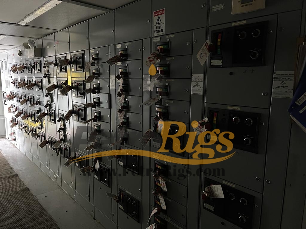
SCR DRIVE SYSTEMSYSTEM INFORMATIONDESCRIPTIONThe SCR Drive System provides electrical power conversion and control for the DC motors on a drilling rig. The system regulates AC power from engine-generator sets and delivers continuously variable DC power to traction motors which are coupled to functions such as Drawworks, Rotary Table, Top Drive, Cement Pumps and Mud Pumps (see Figure 1-1). A typical drive system consists of the following units: Generator Units for control of enginegenerator sets. SCR Units for AC to DC rectification for traction motor power and control. Transformer Feeder Unit - AC feeder breakers to feed step-down transformers that deliver low voltage power for AC auxiliaries such as motor blowers, water pumping, lighting and living accommodations. DW Dynamic Brake - electrical resistance or regenerative brake for Drawworks motors. Field Supply Unit for DC field supply to shunt wound, separately excited DC traction motors. Driller"s Console for control of all drilling functions from the drill floor. Mud Pump/Cement Pump Console for local control of the pumps during maintenance. Motor Control Center containing starters for AC auxiliary motors and feeder breakers for lighting panels and smaller distribution transformers.
SPECIFICATIONSThe drive system conforms to IEEE-45 standards for electrical switchgear. For offshore systems, certification can be obtained from American Bureau of Shipping (ABS), United States Coast Guard (USCG), and Det Norske Veritas. See Table 1-1 for system specifications. Table 1-1. System Specifications ELECTRICALAC Input Prime Power Engine Governor Three phase, 60 Hz, 600 VAC Usable KW depends horsepower of prime mover. on
FUNCTIONAL DESCRIPTIONFigure 1-2 shows a typical one-line diagram. Observe that power from the engine-generator sets is collected on a common AC bus. AC to DC rectification occurs in SCR bridges. The output of the SCR bridge is applied to the DC traction motors via contactors. Contactor logic is set at the Control Console being used. Note that circuit breakers isolate each generator set and SCR Unit from the Main AC Bus.
Figure 1-2. Typical One Line Diagram 3. Adjust the SPEED ADJUST knob (Item 12 on Figures 1-3 and 1-4, Item 9 on Figure 1-5, Item 18 on Figure 1-6) until the SYNCROSCOPE needle (Item 20 on Figures 1-3 and 1-4, Item 17 on Figure 1-5, Item 22 on Figure 1-6) moves clockwise (the engine/generator speed is faster than desired) and the two SYNCHRONIZING LIGHTS (Items 21 on Figure 1-3, Items 19 on Figures 1-4 and 1-5, Items 23 on Figure 1-6) brighten/dim.SCR DRIVE SYSTEM TECHNICAL MANUAL
Description GEN Circuit Breaker AC Kilowatts Meter AC Kilovars Meter AC Ammeter AC Voltmeter Generator Run Light Generator On Line Light Engine Control Switch Synchronizing Switch Ammeter Select Switch Voltmeter Select Switch Speed Adjust Knob Volts Adjust Knob % AC Ground Ammeter % DC Ground Ammeter Ground Fault Indicator Lamps Ground Detector Test Button Power Limit Light Hertz (Frequency) Meter Synchroscope Synchronizing Lights
Description GEN Circuit Breaker AC Kilowatts Meter AC Ammeter AC Kilovars Meter AC Voltmeter Generator Run Light Generator On Line Light Ammeter Select Switch Voltmeter Select Switch Engine Control Switch Synchronizing Switch Speed Adjust Knob Volts Adjust Knob % AC Ground Ammeter % DC Ground Ammeter Ground Fault Indicator Lights Ground Detector Test Push Button Power Limit Light Synchronizing Lights Synchroscope Hertz (Frequency) Meter
Description GEN Circuit Breaker AC Kilowatts Meter Kilovars Meter AC Ammeter Engine Control Run/Off/Idle Switch GEN Run Light GEN On Line Light Push to Close Lighted Pushbutton Speed Adjust Knob Volts Adjust Knob % AC Ground Fault % DC Ground Fault Ground Fault Indicator Lights Ground Detector Test Push Button Generator Synchronization Select Switch Frequency (Hertz) Meter Synchroscope AC Voltmeter Synchronizing Lights Power Limit Light Hour Meter
Description AC Kilowatt Meter Temperature Meter Kilovars Meter AC Ammeter % DC Ground Meter % AC Ground Meter AC Voltmeter Generator Run Light Circuit Breaker Push to Charge Push Button Ground Fault Indicator Lights Ground Detector Test Push Button Circuit Breaker Indicator Lights
Description Ammeter Select Switch Engine Governor Switch Circuit Breaker Switch Voltmeter Select Switch Volts Adjust Knob Speed Adjust Knob Temperature Select Switch Synchronizing Switch Frequency (Hertz) Meter Synchroscope Synchronizing Lights GEN Circuit Breaker
1-9 4. Crank the handle of the GEN CIRCUIT BREAKER (Item 1 on Figures 1-3, 1-4, and 1-5, Item 24 on Figure 1-6) once to charge the GEN CIRCUIT BREAKER. Close the GEN CIRCUIT BREAKER when the needle of the SYNCROSCOPE points straight up, the SYNCHRONIZING LIGHTS go out, and the PUSH TO CLOSE pushbutton on the GEN CIRCUIT BREAKER is illuminated. Position the VOLTAGE ADJUST knob so the KVAR meter gives the same reading as the other generator(s) on line. Turn the SYNCHRONIZING SWITCH to the OFF position. 2. Charge the circuit breaker (if necessary), by pushing the CHARGE pushbutton (for electrically-charged circuit breakers) (refer to Figures 1-3 through 1-6) or by cranking the circuit breaker handle (for manually-charged circuit breakers). Some systems have molded-case circuit breakers. These do not require charging. Close the SCR circuit breaker by pushing the PUSH TO CLOSE pushbutton (this may be mounted remotely or directly on the circuit breaker). Crank the circuit breaker handle once to close molded-case circuit breakers.
1-10 KW SHARING (CONCLUDED) The master generator is the lowestnumbered unit connected to the Main AC Bus. The remaining generators are slaved to the master. For example, if Generator 1, 2, and 4 are connected to the Main AC Bus, Generator 1 is the master. In systems using Auto Share (Auto Sync) AC Control Modules, master/slave floats. No AC Control Module can be the dedicated master in an Auto Share system. The magnetic coupling that exists between paralleled generators insures that all engine generator sets connected to the Main AC Bus at the same time will run at the same speed. The SPEED ADJUST knob on the master generator has total control of the Main AC Bus frequency. The slave units SPEED ADJUST controls are disabled. The combination of KW (Real Power) and KVAR (Reactive Power) sharing between engine generator sets should cause all generator AMMETERS to read about the same value. Any imbalance in the readings of the various KVAR meters can be adjusted by using the VOLTAGE ADJUST knob of the generator that has the lowest KVAR meter reading. POWER DISTRIBUTION Distribution of the total power is governed by the following equation: DCPower Demand = Power Used (Total - AC) Bring additional generators on line to increase the total power available. To increase the total DC power available, increase the total power by putting more generators on line. AC power is usually a small fraction of the DC power. To increase power for a specific DC function, it also helps to reduce the power consumed by the other DC functions.SCR DRIVE SYSTEM20605-45 Rev K
CRISIS OPERATIONUNIT MALFUNCTION The GEN ON LINE and SCR ON lights will illuminate when the respective units are connected to the Main AC Bus. The lights go out when that unit is tripped off-line (disconnected from the Main AC Bus). If a generator\SCR unit becomes inoperative, continue the system operation on other units. SYNC MALFUNCTION If the SYNCHROSCOPE is inoperative, use the SYNC lights to parallel the generators. If both the SYNCHROSCOPE and the SYNC lights fail, use a Multimeter. Switch the Multimeter to a 600 VAC scale. Connect it across the generator circuit breaker from the top to the bottom of any one phase. The voltage will swing from minimum to 600 VAC just as the SYNC lights should change from dim to bright. Adjust the SPEED ADJUST knob for the oncoming generator until the swing slows. Close the circuit breaker when the Multimeter voltage reading is minimum. TRANSIENT AC SURGE The green SURGE SUPPRESSION light will extinguish if a problem blows the Surge Suppression Circuit incoming line fuses.
1-11 SPROCKET SLIP The SPROCKET SLIP light illuminates when Mud Pump assignment contactors trip. This is caused by a sprocket slip, chain failure, or belt slippage on a dual motor mud pump. After the chain drive is repaired, push the SPROCKET SLIP RESET button to extinguish the SPROCKET SLIP light and to allow the contactors to close. GROUND FAULT The three GROUND DETECTOR lights and the % AC GROUND and % DC GROUND meters indicate ground faults. These are only indicators and the fault must be located and corrected. AC ground faults can occur anywhere along the AC power network (generator to AC bus cables, feeder distribution to the AC motors, and the generator control bus in the cubicle itself). The GROUND DETECTOR lights will isolate the fault to one of the phases, and the % AC GROUND meter will indicate the degree of the fault. DC ground faults may occur anywhere along the DC network from the DC (+) and DC (-) buses in the SCR cubicles to the motor cables. Isolate the fault to one motor by observing the % DC GROUND meter. The % DC GROUND meter needle will fluctuate as the faulty motor speed is changed.
SHUT DOWN INSTRUCTIONS1. Turn off the SCR unit by tripping the SCR circuit breaker. The SCR ON light will extinguish. Disconnect the generator from the Main AC Bus by tripping the Generator circuit breaker. The GEN ON LINE light will extinguish. Push the engine IDLE pushbutton. Cool the engine per the engine manufacturer. After the engine cool-down period is over, turn the Generator Control cubicle OFF/IDLE/RUN switch to OFF to stop the engine. Shut down the fuel rack if there is no OFF button.
CAPABILITIESFigure 1-7 shows an SCR bridge Current versus Voltage response curve. Figure 1-8 shows DC series and shunt motors Speed versus Torque curves. These are for a specific brand and model motor. Other brands and models will be different.
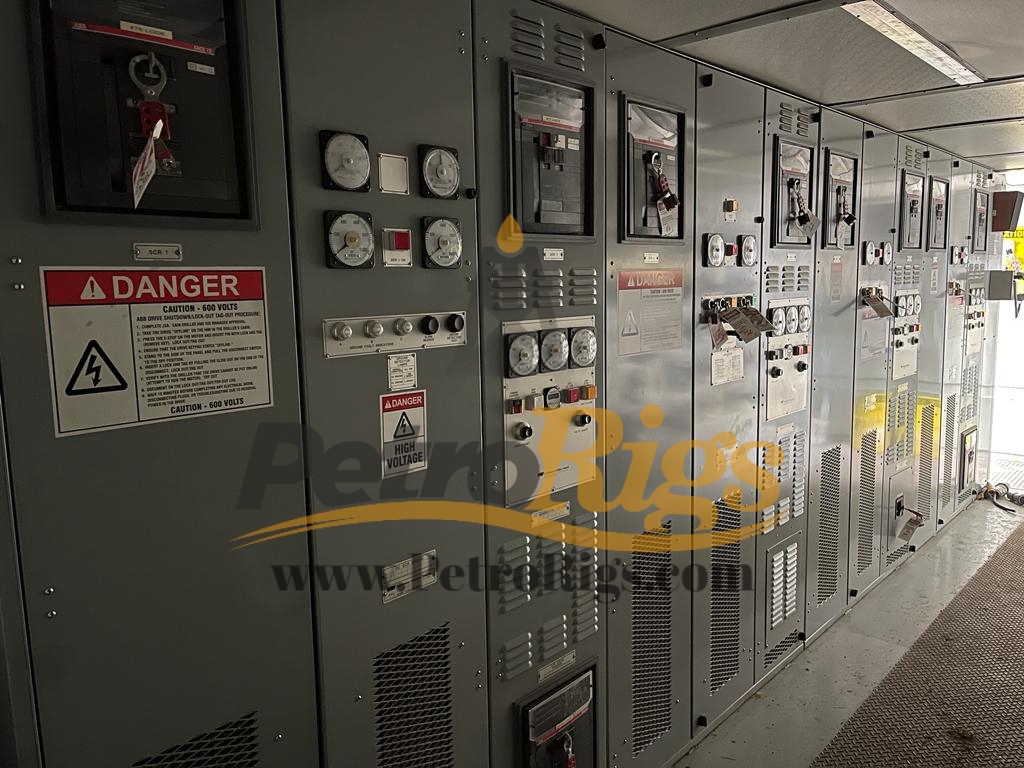
RECEIVING & HANDLINGSCR switchgear is normally installed in a truckload-sized house (see Figure 1-9), a self-contained, structural steel building mounted on skids. Cabling to external devices such as generators, motors and control consoles is terminated at weatherproof plug panels (see Figure 1-10).
If an SCR house was not ordered, refer to the following instructions for installation of the SCR Cubicles. Figure 1-14 shows a typical SCR Drive Cubicle lineup.
CUBICLESPRELIMINARY CONSIDERATIONS Door Clearance The SCR room must be large enough to allow the doors to be opened 90 degrees. The doors cover the full height of the cubicles. The height of the room must have clearance for the cable tray, piping, and ducting. Ventilation and Ducting The room air must be changed twice per minute when the cubicles are enclosed in a room. Ducting in the front and rear of the room should force the air to flow the full length of room. Heat Loss Heat loss for a SCR system housed in a room fully insulated on walls, floor and ceiling, and containing no distribution transformers, is approximately 2.5 tons for each 1,000 HP of DC load. Vibration Pads If the cubicles are mounted in a high vibration area, such as the region close to the engine skid, the cubicles should be mounted on vibration insulating pads. The vibration frequency should be within 30 Hz, and the amplitude should not exceed 0.02 cM. Korfund spring-type vibration isolators are recommended. Location Lift the cubicle with a crane into the general installation area. Use four lifting points per cubicle. Refer to Figures 1-11 and 1-12 for the lifting procedure.
Use hydraulic hand trolleys (Rol-A-Lift or equivalent) to move the cubicles into the exact location. Two trolleys may be required for wide cubicles such as the Motor Control Center. Cover the vertical rest beams of the trolleys with carpeting to protect the finish of the cubicle panels. Slide the trolley horizontal forks all the way underneath the cubicle. Jack up the cubicle approximately 6" (15 cm) above the floor. Push the cubicle carefully into the location, jack down, and remove the trolley horizontal forks. Mounting Butt the sides of the cubicles tightly together. Bolt the cubicles together at the top and bottom using 3/8" bolts. Install the AC bus splices to connect the bus together from cubicle to cubicle. Cable Installation Refer to the cabling diagrams in the SCR job book. Cables between the cubicles are furnished by the customer unless the SCR drive system is installed in a Power Control Building. All power terminations are made through the cubicle top unless otherwise designed. If the SCR system is supplied inside a Power Control Building, power and control cable terminations are at one end of the building. The terminations are copper stubs with an one inch diameter bolt hole. The customer should furnish plated-copper, crimp-type lugs. Avoid screw-type pressure connectors.SCR DRIVE SYSTEM TECHNICAL MANUAL
1-19 If multiple single conductor cables are used to feed the system, transposing of the cables must be considered to ensure current sharing between conductors. Control Consoles The Driller"s Console is typically mounted on top of the Drawworks pneumatic control console. The Mud Pump and Cement Pump consoles are provided with tabs. Each tab has a bolt hole for wall installation. Refer to the respective console drawings for detailed installation instructions. Control cable terminations are made from the bottom with plug-in-type Pyle National connectors or screw-type terminal blocks fed through stuffing tubes. Team Work Maintenance work should preferably be performed by a team of two electricians. This assures help in an emergency situation. Personal Wear Do not wear metallic watch straps, rings, or bracelets. Live Circuit Consider all circuits to be energized unless known to be dead. Tools All electric tools should be grounded. Handles on the tools should be insulated. Do not leave tools in the cubicles after the work is completed. Fuses Close a fuse by pushing on the plastic cover. Do not place a finger underneath the cover. Fire Remove power to the unit under fire. Read the label on the fire extinguisher to be sure it can put out an electrical fire. Water may be used, but be very certain that all power is removed including the power on the main bus.
TESTINGThis section contains information to test the proper functioning of the SCR Drive System. Perform the test daily. If the system fails any part of the test, use the Troubleshooting section to locate the malfunction. SAFETY PRECAUTIONS IF CARELESSLY HANDLED, THE SCR DRIVE SYSTEM CAN INFLICT GRAVE INJURY. SAFETY PRECAUTIONS MUST BE OBSERVED AT ALL TIMES TO PREVENT ELECTRIC SHOCK.
1-20 DAILY TEST Perform the following checks to assure the proper functioning of the drive system. 1. 2. Check lights and meters on cubicles and control consoles. Check Ground Detector indicators. All three lamps should glow a dim orange. The Ground Fault Percentage meters should read close to Zero. Check field current supply of all shunt motors. Ensure that KW"s and KVAR"s are shared between all the generators on line. During tripping, listen for switching action of the DW Dynamic Brake contactor. Ensure that all SCR blowers are running. System more reliable and last longer. A reliable system is less likely to suffer sudden failures or deteriorate below the performance specifications. The system components are vulnerable to three factors: inferior quality, harsh operation and severe environment.
HARSH OPERATIONThe drive system should be operated within its capabilities. Operation above the ratings subjects the system to severe strains. The controls should be handled with care. A harsh switching action can generate a damaging transient overload.
MONTHLY TEST Perform the "Mechanical Overspeed Trip" and "Reverse Power Trip" Functional tests, located in Table 2-4 (see Section 2). 1. Check waveshape of SCR Amps at the test pins on the DC Control Module. See the SCR Unit section for further details. Inspect the cooling inlet filters and clean/replace as necessary.
ENVIRONMENTHEAT Components can fail suddenly due to overheating. Even though the drive system is rated between -22F (-30C) through 104F (40C), the system operation is more reliable at normal temperatures. Components age faster at temperature extremes. The blowers in each SCR cubicle remove the heat from the electrical assemblies. As a further precaution, vital units such as the SCR bridges and electronic modules have heat sinks for faster cooling. Inspect theSCR DRIVE SYSTEM TECHNICAL MANUAL
SERVICINGServicing consists of cleaning the system components and replacing those which have become defective or worn out. Periodic servicing will make the SCR DriveSCR DRIVE SYSTEM20605-45 Rev K
1-21 assemblies frequently for indications of overheating such as charring or burned insulation due to loose connections. Replace the damaged components even thought they may not have failed completely. VIBRATION The drive system units do not generate vibrations. However, vibrations from rotating machinery such as the generator set cause mechanical stress which can loosen connections and crack insulation. DUST Dust is attracted to high voltage switchgear surfaces because of the static electricity charge. As a result, circuit discontinuities, or even shorts can occur. MOISTURE Moisture aggravates problems caused by dust. The contaminants cake on the components and conductivity is increased. Further, corrosion can occur. Servicing consists of three operations: cleaning, inspection, and replacement. CLEANING 1. Wipe clean the cubicle and component surfaces with a lint-free cloth moistened with a mild cleaning solvent. Be sure to leave the surfaces dry. TURN OFF THE MAIN POWER TO THE SYSTEM BEFORE CLEANING. TEST THE CLEANING SOLVENT ON A SMALL SURFACE TO MAKE SURE IT DOES NOT DAMAGE THE PLASTIC PARTS OR INSULATION, OR REMOVE PAINT. 2. Clean all cubicle and air conditioning filters. Check Driller"s console and Foot Throttle for air pressure. If there is moisture inside the compartments, the dryer in the air line may be clogged. Check assignment contactors. Inspect the coils for signs of overheating such as discoloration or charred insulation. Check contacts for corrosion or pitting. Inspect the freewheeling diodes; also inspect auctioneering diodes in the system. INSPECTION Check all components for overheating and corrosion. Replace damaged components even if not completely failed. Inspect cables and wires for broken or burned insulation. Tighten all connections and check switches, knobs, and buttons for easy movement. CARELESS INSPECTION ITSELF CAN CAUSE MALFUNCTIONS. DO NOT TUG CABLES AND WIRE HARNESSES, SHAKE THE ELECTRONIC ASSEMBLIES OR FIDDLE WITH THE KNOBS. EMPLOY VISUAL INSPECTION AS FAR AS POSSIBLE. Operating conditions dictate the servicing period. Adhere to the following schedule during the initial period and adjust it according to need. CONNECTIONS Experience has shown that many problems with electrical equipment are the result of loose connections. Periodic checks for tightness can be helpful. WEEKLY SERVICING
1-22 ENVIRONMENT (CONCLUDED) 4. Clean tachometer pickup plugs. Do not screw pick up in too far. Flywheel will damage coil upon starting diesel. Check AC leakage for every SCR bridge. 5. 6. Open and inspect all generator and traction motor covers. Open all fuses in the system and high-resistance check the main three phase bus bars before applying power. Remove covers and inspect SCR bridges. Clean as necessary. Reconnect HOC batteries. If good, they will fully recharge within 24 hours. Clean all potentiometer windings (speed adjust, voltage adjust, hand throttles, foot throttle). Tighten all bus bar bolts and screw connections. Manually phase-up each SCR bridge as soon as possible. Inspect all power resisters for cracks. Check AC leakage on all SCR bridges. Check knob settings on EGB-10P or 13P actuators. Check resistance of all magnetic pickup circuits and all actuator circuits. Check compatibility of all modules. Check outputs of hand and foot throttles. Check current and voltage feedback for all SCR bridges. Perform emergency-off and reverse power trip tests for all engines. Verify sync circuits with a VOM. If equipment has been idle for more than one year, all electrolytic capacitors should be replaced.
STORING AN SCR DRIVE SYSTEM1. 2. Disconnect HOC batteries at the battery terminals. It is important to keep the SCR house interior dry while stacked. Install covers on all external connectors on the plug panels. Place corrosion inhibitors in consoles and cabinets. Seal any openings to keep varmints out. Lift the brushes on traction motors. Apply power to generator and traction motor heaters if possible. Heaters in electrical equipment areas are helpful. Cover traction motor blower openings.
REMOVING AN SCR DRIVE FROM STORAGE AND PLACING IT IN SERVICE 1. Inspect bus bars for debris. Inspect and clean throughout cubicles, consoles, MCC cans and underneath the main and switchgear line-ups. Physically rotate the SCR blowers. Manually operate all motor starters and contactors before powering up. Open and inspect all modules.
TROUBLESHOOTINGOVERVIEWTroubleshooting allows the isolation of a malfunctioning SCR Drive System unit. It consists of first looking at the broad possibilities of failure, and then breaking down the likely possibility into successively smaller trouble spots. Examine the whole system as it is situated between the generators and the loads. Then narrow the search to a cubicle or console, then to an internal assembly, and finally to a component. The malfunction can be quickly located by seeking out signs of trouble, such as extreme readings on the meters, tripped circuit breakers, and smoking components. A step-by-step troubleshooting approach should consist of the following items: malfunction analysis, analysis of front panel indicators, systems analysis, and signal tracing.
ANALYSIS OF FRONT PANEL INDICATORSMany malfunctions can be located by analyzing the meters and lights on the front panel. Warning lights on the cubicle panels flag ground faults, AC surge, sprocket slip, and reverse power conditions. Operational lights indicate whether a SCR or a Generator is on the bus. Even voltmeters and ammeters provide valuable troubleshooting information. For example, a stalled motor is indicated by high current, and low voltage. Low current and high voltage is an indication of an unloaded motor.
MALFUNCTION ANALYSISTroubleshooting is easier and faster if the nature of the malfunction is pinned down. Sometimes, the faulty behavior of the system may be caused by operator error. For example, the Driller may forget to turn on the lockout switch, open the throttle, and assume that the SCR unit is defective. The faulty behavior of a motor or generator may be blamed on the SCR system. Make sure the fault is not outside the system before making extensive repairs such as replacing a SCR cell. If the malfunction occurs off and on, it may be useful to keep a log of the system parameters with a strip chart recorder.SCR DRIVE SYSTEM TECHNICAL MANUAL SCR DRIVE SYSTEMDC ELECTRONIC MODULE CIRCUIT BREAKER
1-24 SYSTEMS ANALYSIS (CONCLUDED) A malfunctioning unit does not provide the correct outputs. The fault may be due to incorrect inputs. If not, some of the assemblies within the unit may be defective. To troubleshoot, the system, first isolate the faulty unit by examining the outputs of the suspected units. Then examine the inputs to the faulty unit. If one of the inputs is incorrect, trace the signal from the incorrect input to its source unit. If, however, the inputs are correct and the outputs are incorrect, troubleshoot the defective unit. Isolate the fault to any one of the unit assemblies by a similar system analysis. Inputs to many of the SCR Drive System units are of two forms: power and control. For example, a SCR cell must receive the AC supply and the control firing pulse at the gate. If both the inputs to the SCR cell are correct and the output of the SCR cell is incorrect, the cell is defective. The defective unit can be easily located by tracing signals associated with the malfunction. The motor can be operated on any one of the two power lines (refer to Figure 1-16). If it fails to run, the fault can be in the motor, the assignment switch, or the power lines. The power line can be checked out by simply switching the motor to one of the other lines. If the motor runs, then obviously, the first power line is defective. Each power line is made up of components in series. If the power line circuit is defective, all the components and the wiring must be suspected. The defective component can be located by tracing the power supply from the motor back to the generator. Begin the signal tracing at the motor. If power is present at the motor and the motor is not running, the motor is defective. If power is absent at the motor, check for its presence on both sides of the contactor. If power exists on the SCR side, but not on the motor side, the contactor is open. Signal tracing should continue back toward the Generator until the defective component is located. In extremely long series circuits, it may be convenient to divide the circuit in half. Begin the probe in the middle. If the signal is missing, trace back toward the generator until the signal is regained. If the signal is present, trace away from the generator until the signal is lost.
SPECIAL TOOLS AND EQUIPMENTThe following instruments are needed to troubleshoot the SCR Drive System. MULTIMETER The Simpson Model 250 (or equivalent) is recommended to measure voltage and resistance values. The meter should be insulated, rugged and possess:DC/AC Volts:Zero through 1,000 Volts in several ranges. Accuracy: 3% of full scale. Ohms: Zero through 10 M in several ranges. Accuracy: 2% of arc length.
AC/DC CLAMP-ON AMMETER This meter is used to safely measure high currents. The Columbia Model 1000A is recommended. OSCILLOSCOPE The oscilloscope is used to check the SCR gate pulses and ripple on various DC voltages. The Tektronix Model 305 (or equivalent) is recommended. The unit chosen should have >3 Inch diagonal viewing screen and two channels for comparing two signals.
It is recommended that digitaltype meters not be used for measurements in power circuits. It has been found that, in some cases, reading inaccuracies may be induced by digitaltype meter usage. Digital multimeters may be used to measure voltage and current signals in the SCR drive but you should be aware that some digital meters are overly sensitive to the high electrical noise typical of that found in any switching high power supply. Digital meters that are not designed with proper filtering and measuring techniques and can give inaccurate readings.
CUBICLE REPAIRRepair of the SCR Drive System normally consists of repairing an assembly within a system unit. A system unit is not replaced unless it is damaged beyond repair. When a unit is replaced, perform a functional test on it before operating the system. Refer to the respective unit manual for test instructions.2. Release the wiring harness by removing each wire from the terminal board.FS-047-05
Reconnect the wiring harness by replacing each wire on the terminal board. Ensure that each wire is correctly placed and that the retaining screw is tightened.


 8613371530291