
ross hill scr mud pump drive quotation

0002-0390-12 1K 25W Dual potentiometer assembly ROSSHILL for mud pump0002-0390-12 1K 25W Dual potentiometer assembly ROSSHILL for mud pump0002-0390-12 1K 25W Dual potentiometer assembly ROSSHILL for mud pump
The Zeefax Total Rig Auditavoids downtime and ensures rig systems remain operational and reliable. Many Drilling Companies will invest in a completeRig Auditin the knowledge that it offers a comprehensive overview of the state of their rig, which can also be submitted for compliance and due diligence purposes.SCR Training Simulator
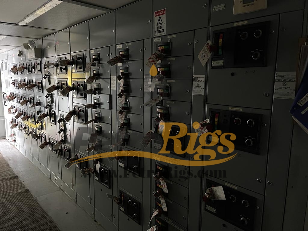
Every Drilling Rig must have a Power Control Room – sometimes also known as an SCR (standing for Silicon Controlled Rectifier) System – which forms the functional heart of the power control of the drilling operations. Typically, SCR systems comprise a large steel room, inside of which will be a range of Motor Control Centres, Engine & Generator Controls, SCR Control cubicles, and other instruments and systems used for drilling purposes.
SCR Systems usually operate at 600V, and clearly, these systems can be extremely dangerous if not operated correctly and carefully by suitably trained operators. It is therefore vital that drilling engineers and operators are well trained using a combination of class room tuition and on-the-job training.
In response to this need, Zeefax have created the world’s first full size SCR Training Simulator, which accurately mimics the a real SCR; it looks and feels like the real thing, providing a realistic experience of live field operations – but without the dangerous high voltage. This system was created specifically for Naftogaz – for more details, click here.
A key feature of the simulator is the addition of the on-board computer system, which mimics all of the signals that would normally come into this SCR system from the live engines and generators, including the motors running the mud pumps, the rotary table or the Drawworks, etc. and can also simulate a wide range of known faults, allowing trainees to experience first hand problem solving in the safety of the simulator, before they experience the live system.GE Legacy Drive Systems
Used the same type SCR bridge as the Generation III, but rated at only 1200-1500 amp since the heat sink assembly is of a slightly different design. This system uses the GE generator GEM modules controls.
1980’s, 900amp. SCR bridges using the GE GEM Generator Control. As the bridges are small it requires two SCR bays to run a two-motor Mud Pump or Drawworks.
If you are interested in applying for this position, then please send us your latest CV and a covering letter toTest and Calibration Engineer – SCR products
Zeefax is the value source for parts and services for your legacy GE Drive and Generator Control Systems. We hold an inventory of critical spare parts and can provide comprehensive service solutions including Repair and Return of Modules and PCBs.
Zeefax operates a comprehensive repair and return service for all legacy GE Drive and Generator Control Systems. which includes cleaning, testing, repairing or replacement of defective components and a full system load test. This service includes a 6-month limited warranty.
Zeefax understands that replacement of a complete SCR Control System is often not viable due to the large cost and loss of production due to system downtime. At Zeefax we can offer a comprehensive service to support your legacy GE Drives and give it a renewed lease of life. That not only includes supply of spare parts and a repair/calibration service; qualified service engineers with years of experience with these Drives are available for regular Health Checks, fault-finding and general support purposes.Careers
In response to many customer requests, we have designed our own version of the legacy Ross Hill Controls AutoSync AC generator control module; the new module has been completely re-designed and incorporates all new digital circuitry as well as optional expansion capability to future proof the module.
Advancements in technology mean that many of the power semiconductors which were built into SCR systems 30 or more years ago have been superseded by new devices, often with improved specifications.
Our engineers are able to ensure that, when the original component is not available, a suitable replacement can be found. If the replacement is not an exact fit, we can engineer an adaptation to ensure continued serviceability of legacy equipment.Hill Graham Controls (HGC)
Following our acquisition of Hill Graham Controls (HGC), Zeefaxis in a unique position to offer total support for all legacy Hill Graham and Ross Hill Controls (RHC) systems both in the UK and throughout the world.
Zeefax’s unique experience and expertise has allowed the company to design, manufacture, supply, repair and calibrate many of the control modules used within older Hill Graham installations, as well as other manufacturer’s systems, including Ross Hill Controls (RHC) type systems.
In recent times,Zeefax has developed and brought to market a new digital AutoSync module, with an improved contemporary design and operation. This advanced module occupies the exact same footprint and has pin-for-pin connection compatibility with the now obsolete Ross Hill module, thereby providing a simple and cost effective upgrade path for existing users of the AutoSync module.
As part of our maintenance and service offerings for SCR systems, Zeefax is able to mobilise support and engineers to provide technical assistance during emergency shutdowns and downtime periods.
Given our years of experience and unique position to offer total support for all legacy Hill Graham Controls (HGC), and other manufacturer’s systems including Ross Hill Controls (RHC), IPS, and GE Micro Drill SCR systems, Zeefax can provide a full range of technical services for installation, commissioning, and ongoing operational support.SCR System Health Checks
The time to find out if your system is reliable is when operations are quiet – not during critical well operations – so the Zeefax SCR System Health Check is designed to identify potential weaknesses and either repair or replace immediately, or mitigate against these until a repair or replacement can be effected – usually at a quite time.
For reliable operation, the contact between the SCR devices and the heatsinks must be as good as possible but over time, and especially in offshore installations, corrosion may attack the interface between the SCR device plating and the aluminium heatsink. If corrosion is present it takes an expert to decide if refurbishment is required because as long as the damage is minimal and the two elements remain undisturbed, the mutual corrosion may still maintain a good contact.
Since our acquisition of Hill Graham Controls (HGC), our module repair facility and engineers, have been able to test and calibrate modules sent to us for repair within a quick turnaround period. In an important development, Zeefax has designed and built a new AC and DC Module simulator, to provide an improved testing platform for Hill Graham and Ross Hill type AC and DC modules. In particular, the AC module simulator is much improved over the older unit, and provides a greatly enhanced engine control and start-up simulation.
In addition, we are able to repair and re-calibrate most Hill Graham and Ross Hill type printed circuit boards (PCBs), including Power Limit, Field Supply Regulator, Sprocket Slip, Drillers Console, DC Auxiliary, SCR Auxiliary and Generator Exciter PCBs. Furthermore if following evaluation, repair is not possible, in many cases we can supply new manufactured boards using the original designs, but enhanced by us using modern components and manufacturing techniques. In this way, we can help to ensure that legacy systems remain operational and continue to provide reliable and trouble free service beyond their expected life.Motors & Generators
Even given the relatively controlled working environment of typical SCR pods, the conditions can often cause deterioration to both electrical and mechanical performance, requiring removal of the unit from the system, followed by refurbishment and renovation.
The heat sinks are inspected and if required, will be re-machined to ensure excellent electrical contact is maintained. Importantly, the SCR Thyristor ‘puck’ is replaced, and very special attention is given to the clamping torque and orientation.
If you would like to know more about the range of available Driller’s Foot Throttles, please call or email us, and we will be pleased to assist.SCR Blower Assemblies
An important part of every system is the forced air cooling, which is vital to ensure continuity and reliability of operation of the SCR stacks. It is essential that the heat generated during operation is reliably carried away, and Zeefax now produce a series of SCR Blower Assemblies which are compatible with the those used in legacy Hill Graham and Ross Hill type systems.
The Zeefax SCR Blowers are designed to operate with voltages up to 600 V @ 50 or 60 Hz; the operating voltage needs to be specified at the time of purchase (see the details and specification form below) and the blower may be configured with either Single or Duplex impellers and with or without base frames.
In order to aid potential users with the selection of replacement blowers, we have created a simple form which can be used to provide the few technical details we require. In this way, we can ensure that any SCR Blower supplied by us is fully compatible with existing assemblies, and will then install directly into the available location with minimal re-work required. You can download this form from this site; please fill it in and return it to us to receive a quotation.
Through our in-house R&D, we are developing improved specification products as replacements for legacy Hill Graham Controls or Ross Hill Controls boards; we can provide original replacements for many of the PCBs used on these systems, and by using modern techniques and components, we can even improve on some of the design features of the original products to enhance reliability and functionality.

It is an unfortunate characteristic of SCR systems that the Power Factor (the relationship between real and reactive power) is poor – often down as low as 0.4 – which maeans that the KW capacity of the engines is under-utilised. This often leads to frustration because the rig runs out of power, yet the engines may be only delivering half of their full-load capacity. This article explains how the Power Limit system works and what can be done to ensure it is working at its optimal level.
In general terms, the KW the system consumes is provided by the engine. The other limitation on power delivery is the current capacity of the generator, which is often expressed as a VA or KVA value. SCR systems are designed with something like a 0.7 Power Factor rating; in other words, the KW of the engine will be 0.7 x the KVA rating of the generator. This goes some way to compensating for the poor Power Factor, but often is insufficient during operations where where the Mud Pumps are heavily loaded. However, measures are still available to ensure that the system is delivering what it can within these physical limitations, one one thing to ensure is that the Power Limit system is working optimally.
The purpose of the Power Limit is to prevent rig blackouts in the event of sudden increases in load. The original philosophy also was to allow the minimum number of engines to be run and maximise efficiency but most drilling operators prefer not to run up against these limits and demand as much power as is available. The Power Limit system measures the KW load of the highest loaded engine, and the current load of the highest loaded generator and compares this to a pre-set reference to determine if Power Limiting of the SCRs should occur. Furthermore, some systems have an initial 60% KW limit, which then opens up to 100% once this threshold has been reached under ramped control. This is to allow the engine turbo-chargers to spin up. Once above this threshold only the 100% limit is in operation, unless the load dips below 60% in which the ramp is re-set.
We design, deliver and support electrical engineering projects, from simple machine controls to large scale production and process line systems. Our key skills include:Hill Graham and Ross Hill Type SCR Drives andGenerator Controls
We have particular expertise with power systems and DC or AC variable speed drives. We have highly specialised knowledge about drive systems for Oil Rigs, and have unrivalled experience in design, modification, repair and testing of Ross Hill and Hill Graham type SCR systems.
Using sophisticated software we are able to model power systems and calculate short circuit levels to ANSI and IEC standards. From the same on-line drawing we can generate time/current co-ordination curves and a comprehensive schedule of device settings. Our Harmonic Analysis tool is able to accurately predict expected levels of total harmonic distortion introduced by variable speed drives, UPS’s and other harmonic sources, and analyse the effect of adding filters to the system.
JOTON has forged relationships with many of the worlds leading industrial equipment suppliers and, together with it’s own technical and manufacturing capabilities, can source or manufacture a wide range of spare parts for Westinghouse, GE, Ross Hill and Hill Graham SCRsystems.
We are able to identify Ross Hill or Hill Graham parts from the original part number, and can provide exact equivalents where these are available. Where an exact replacement is not available, either due to limited supply or obsolescence, Zeefax can engineer an alternative or recommend a near equivalent.
DSL can provide you with exact replacements for your Hill Graham or Ross Hill systems. We have built a unique database of these specifications, and this, combined with the experience and expertise of our technicians (former employees of Hill Graham in the UK) enables us to re-engineer, and even improve on, the original specification.
We believe we are the only company in the world able to provide replacement AutoSync modules for Ross Hill and Hill Graham systems. In order to improve on the original design, this product is fully digital, but is an exact replacement, occupying the same footprint and having the same pin configuration.
DSL are today developing improved specification products as pin-for-pin replacements for legacy Ross Hill and Hill Graham technology. We can provide many of the printed circuit boards used on these systems, and even improve on some of the design features of the original product to improve reliability, robustness or functionality.
Advancements in technology mean that many of the power semiconductors which were built in SCR systems 10 years ago have been superseded by devices with better specifications. Specifying replacement or equivalent devices is a skilled task, but our engineers are able to ensure that, when the original component is not available, a suitable replacement can be found. If the replacement is not an exact fit we can engineer an adaptation to ensure continued serviceability of legacy equipment.
DSL has designed and built a new type of AC and DC Module simulator, both provide a better testing platform for standard Ross Hill and Hill Graham type AC and DC modules. In particular, the AC module simulator provides a much improved engine control and start-up simulation.
In addition we are able to repair and re-calibrate most Ross Hill and Hill Graham printed circuit boards (PCBs), including Power Limit, Field Supply Regulator, Sprocket Slip, Drillers Console, DC Auxiliary, SCR Auxiliary and Generator Exciter PCBs.
All these over-voltage refer to peak voltage, but SCR elements are damaged, which are usually eliminated by using varistor, namely the surge suppression circuit.
When SCR positive and negative busbar outputted by cabinet is shortly earthed directly or indirectly, the indication light will be more bright (dark bright under normal condition) and DC ground percentage meter indicates positive or negative end earthing, which indicates ground degree.
Modern Drilling practices demand additional mud pumping capabilities which was not envisioned in older systems. JOTON can revitalise a rig by adding a third Mud Pump and add-on mini console.

MUD SYSTEM: Shakers 2each Derrick, Construction Crimp Wall Tanks Active Mud System 1,500 BBL (Can add 2x 500 BBL Reserve mud tanks available if needed for an additional cost)

REVISION HISTORYRev. A B C D E F G H J K L Description Initial Release Added Revision History page and Drawing Number in footer. Revise Figures 4-9 and 4-10. Changed writeup and figures for Mud Pump. Make text and formatting corrections. Update and revise Figure 4-1. Change font size of note on page 4-1 and remove page break on page 4-2. Update figures. Add photo numbers and correct errors in text. Convert to Word 97 format. Minor formatting changes. Minor formatting changes. Add Table of Contents codes. Correct Level 5 and Level 6 styles and errors. ERO/ECN # 041251 C23257 C23706 C24365 C24670 C25761 C26005 C28670 C28926 C28935 C29222
DRILLER"S CONSOLEOPERATIONDESCRIPTIONThe Driller"s Console is the primary control for the rig DC functions. It is installed on the drill floor near the Drawworks and contains an Assignment switch to apply power to various combinations of functions suitable for tripping or drilling. In addition, the Driller"s Console houses a lockout switch and throttle for each function. Lights on the Driller"s Console panel indicate the on-line status of the generators, SCR units, and auxiliary AC devices such as blowers, chain oilers, etc. SPECIFICATIONS Refer to Table 4-1. WHEN AN SCR IS ASSIGNED AND A FUNCTION SELECTOR (SUCH AS MP1 OFF/ON) IS SELECTED, THE MOTOR(S) IS/ARE CONNECTED TO THE SCR DRIVE. THE MOTOR(S) MAY ROTATE EVEN THOUGH THE HAND THROTTLE IS IN THE FULL COUNTER-CLOCKWISE POSITION. IF MOTOR ROTATION IS POTENTIALLY HARMFUL, PLACE THE FUNCTION SELECTOR TO OFF. THIS WILL DEASSIGN (DISCONNECT) THE MOTOR(S). The Driller"s Console is pressurized. The customer should provide a dry air bleed at 75 to 150 PSI.Electrical input The Drillers Console does not require an independent power supply. It receives these voltages from the other SCR Drive System units. 115 VAC from the Generator Sync section. 14 VDC from each SCR Unit. -14 VDC Contactor Power Supply used to develop contactor control signals associated with each traction motor. There are four outputs: Zero to -8 VDC throttle reference signals back to the SCR Units for each DC function. -14 VDC contactor control signal for each traction motor. -8.2 VDC supply for the DW Foot Throttle rheostat. 120 VAC to MCC Relay Pan.
INDICATORS AND CONTROLSFigure 4-1 shows the various types of indicators and controls on a typical console. The numbers shown with parentheses in the following description indicate items on Figure 4-1.
The GEN and SCR Status Lights (Items 3 and 4) illuminate when the corresponding units are connected to the Main AC Bus. The positions of the ASSIGNMENT Switch (Item 1) are arranged as the hours on a clock, with the vertical (12 O"clock) position being OFF.
12Item 1. 2. 3. 4. 5. 6. 7. 8. 9. 10. 11. 12. 13. Description ASSIGNMENT switch POWER LIMIT meter GEN Status lights SCR Status lights BLWR Status lights POWER LIM light ROTARY TABLE ammeter ON-OFF switch EMERGENCY OFF switch FWD-OFF-REV switch RT LIMIT switch Hand Throttle hand wheel Drawworks Foot Throttle
4-3 Positions on the left side of the ASSIGNMENT Switch (positions 7 through 11) are designed for tripping and those on the right side (positions 1 through 5) are intended for drilling. The Driller, however, is free to choose whichever is needed at any time. For each of these positions of the ASSIGNMENT Switch, the number in the blocks refer to the SCR units. The function it drives is listed below the number in the block. In DRILLING positions, DWA and DWB motors are connected in series (DWS). This provides full lifting capability, but only half the hoisting speed. On one SCR bridge in TRIPPING positions, the motors are connected to separate SCR bridges, giving full hoisting speed. The BLOWER Status lights (Item 5) are associated with auxiliary AC devices of the corresponding DC functions. For example, the DW BLOWER light illuminates when all auxiliary devices of both the Drawworks motors such as blowers and chain oilers are switched on. There are LOCKOUT Switches (Items 8 and 10) for each DC function. Once turned ON, the corresponding Hand Throttle wheel (Item 12 - there are four) is rotated clockwise to turn it from Zero to maximum speed. WHEN AN SCR IS ASSIGNED AND A FUNCTION SELECTOR (SUCH AS MP1 OFF/ON) IS SELECTED, THE MOTOR(S) IS/ARE CONNECTED TO THE SCR DRIVE. THE MOTOR(S) MAY ROTATE EVEN THOUGH THE HAND THROTTLE IS IN THE FULL COUNTER-CLOCKWISE POSITION. IF MOTOR ROTATION IS POTENTIALLY HARMFUL, PLACE THE FUNCTION SELECTOR TO OFF. THIS WILL DISCONNECT THE MOTOR(S). MECHANICAL The Drawworks Foot Throttle pedal (Item 13) is pressed to operate the Drawworks once the DW Hand Throttle (Items 12) is rotated out of the OFF position. The RT ammeter (Item 7) indicates current drawn by the Rotary Table motor. This is an indication of developed torque. The RT LIMIT knob (Item 11) is rotated clockwise to increase the torque limit on the Rotary Table motor from 0 to 10. The POWER LIMIT meter (Item 2) indicates percentage of available total power capability of the generators and SCRs on line being consumed by the load. The POWER LIMIT light (Item 6) illuminates when the generators connected to the Main AC Bus approach (90%) their maximum capability. The EMERGENCY OFF button (Item 9) is pressed to disconnect power to all DC functions in case of an emergency.
4-4 4. Check the SCR status lights to make sure the SCR units to be used are connected to the Main AC Bus. On Propulsion or Winch systems, ensure that the SCR units to be used have been assigned to DRILLING at the Control Room Console. 11. 6. 7. Set the ASSIGNMENT SWITCH to the position desired. Set the appropriate LOCKOUT SWITCH to ON, FWD, or REV, as desired. The corresponding BLOWER Status Light will illuminate. Main AC Bus and the POWER LIMIT Light illuminates, all the equipment will still run, though at reduced speed. Speed reduction is performed automatically by a Power Limit circuit to prevent overloading of the engine/generator sets. When changing direction of Drawworks or Rotary Table from FORWARD to REVERSE (or vice versa), first turn the HAND THROTTLE (Items 12) completely counterclockwise to OFF. Let the motor come to a complete stop before switching the ON/OFF LOCKOUT Switch (Item 8) to the opposite direction. Otherwise, damage may result to the SCR unit as well as the Drawworks or Rotary Table.
4-5 THE DYNAMIC BRAKE MAY NOT SET IF THE HAND THROTTLE SETTING (CATHEAD SPEED) IS VERY HIGH. ROTARY TABLE 1. To turn on the Rotary Table, perform the preceding General Instructions. 2. Observe the RT AMMETER periodically to check the current drawn by the motor. The torque limit will not be exceeded if the RT LIMIT knob is set to match the pre-determined current limit even if pipe torque forces the Rotary Table to stall. 3. If the Rotary Table stalls, but more torque is required, the torque limit can be raised by rotating the RT LIMIT Knob clockwise. DO NOT EXCEED THE CURRENT LIMIT SET FOR THE PRESENT OPERATION. IF THIS LIMIT IS REACHED AND THE ROTARY TABLE TORQUES UP AND STALLS, SLOWLY TURN THE RT LIMIT KNOB COUNTER-CLOCKWISE TO THE MINIMUM SETTING. MUD PUMP/CEMENT PUMP 1. To turn on the Mud or Cement Pump, perform the preceding General Instructions. Be sure to turn ON the Mud or Cement Pump LOCKOUT switches. 2. For any maintenance activity, the pumps can be operated from the Mud or Cement Pump Console. The Driller"s Console LOCKOUT switch must be switched on before either Pump Console can be operated.SCR DRIVE SYSTEM TECHNICAL MANUALTO DW FOOT THROTTLE TO ROTARY TORQUE INDICATOR DRY AIR BLEED
MAINTENANCERefer to Section 3 (SCR Unit) for general information regarding maintenance and testing of the SCR Unit. The following part of this section provides installation, testing, and servicing instructions specific to the Driller"s Console.
4-7 Table 4-2. Driller"s Console Functional Test ACTION1. Open all SCR Circuit Breakers. The Circuit Breaker may be a switch. 2. Jumper the auxiliary contacts of the SCR #1 2. switch (CB). Place the jumper between TB8-4 to TB8-5 in the SCR #1 Cubicle. 1.
RESULTThis prevents SCR Bridge phase up when the assignment contactors are closed. This enables assignment contactors to be closed in SCR #1 for the function being tested. The green SCR ON lamp on the Drillers console will illuminate. In the example, the MP1 contactors will pick up, the blowers on Mud Pump motors of MP1 will run, the auxiliary functions (Rod Oiler, Chain Oiler, etc.) will operate and the MP1 BLOWER ON lamp on the Drillers Console will illuminate. Monitor the throttle voltage variation at MP1 INPUT (pin 125) on the DC Control Module. Measure it in respect to ground. It should be Zero VDC when the MP1 HAND THROTTLE is fully counter-clockwise (minimum) and increase to -8 VDC as it is rotated fully clockwise (maximum). Refer to the control logic diagrams in the SCR System Print Book to identify the DC Control Module numbers for the desired test functions. Monitor for Drawworks Foot Throttle voltage on the pin 114 of the DC Control Module as the Foot Throttle is slowly depressed. The voltage will vary from Zero VDC when the Foot Throttle is not depressed to -8 VDC as the Foot Throttle is fully depressed. There is no measurable result from this functional test action.
On the ASSIGNMENT Switch, select a 3. function to be tested (for example, MP1 may be run on SCR #1 in the ASSIGNMENT switchs 2 oclock position by rotating the ASSIGNMENT switch to the 2 OCLOCK position and turning the MP1 OFF-ON switch to ON. Rotate the MP1 HAND THROTTLE fully 4. clockwise while observing the throttle voltage variation.
Repeat Steps 2 through 4 of this functional test for each SCR and each function powered by the SCR system. Remember to move the jumper for the auxiliary contacts of the SCR switch to TB8-4 and TB8-5 of the SCR being tested. Verify the Drawworks Foot Throttle operation. 6. Make this check for each SCR. Jumper TB8-4 to TB8-5 in only one SCR at a time.
SERVICINGRefer to Section 3 (SCR Unit) for general servicing instructions. CONSOLE 1. Examine the internal assemblies periodically for signs of corrosion. Corrosion is possible if the front panel door is not properly sealed or if the air or purge air is bringing in a large quantity of moisture. 2. Rotate the hand wheels and the switches and examine the switch and rheostat assemblies behind the Driller"s Console door panel. Check the switch contacts and rheostat wiper arms carefully. Test the rheostat linkage for tightness.
DW FOOT THROTTLE Perform the following service on the Foot Throttle every three months under normal conditions. 1. Remove the Foot Throttle (refer to Figure 4-4) and open the rear dust cover. 2. Check and re-tighten the set screws. Ensure that the Foot Throttle potentiometer returns to zero. 3. Check that the rheostat wiper does not rub the wires entering the Foot Throttle. 4. Grease the bearing surfaces. 5. Reassemble carefully to ensure that the Foot Throttle box is watertight.
Table 4-3. Driller"s Console TroubleshootingPROBLEM AND POSSIBLE CAUSE MOTOR WILL NOT RUN A. Generator SCR units may be A. Check the STATUS LIGHTS. OFF. B. If motors are shunt-type, the B. Check that the Field Supply is ON and that the FIELD field current may be zero. CURRENT AMMETER reading is 50 Amps. C. Assignment contactors have not picked up. may C. If the appropriate assignment contactors have not closed, trace the -14 VDC contactor logic signal through the appropriate assignment logic. Refer to Figure 4-7 (Driller"s Console Schematic Diagram Shunt Motor System). ACTION
D. The HAND THROTTLE signal D. The HAND THROTTLE reference signal should be is not reaching the DC Control between Zero and -1 VDC at OFF and up to -8 VDC at Module. MAXIMUM throttle. Check the signal at the selected SCR unit TB. Trace the direction in which the signal is absent. E. The DYNAMIC BRAKE is ON if E. Either the B motor is leading the A motor OR the A motor DRAWWORKS is selected and DC Control Module is defective. the HAND THROTTLE is set for CAT HEAD SPEED. HORN SOUNDS A. The DRILLERS CONSOLE is A. Check the dry air bleed for leakage. no longer pressurized. B. The blower has not switched B. Trace the 115 VAC motor control logic. on, or fails to start running. FOOT THROTTLE DOES NOT WORK A. The Foot Throttle rheostat is A. Check the reference signal at pin 114 of the selected SCR inoperative. unit DC Control Module. Check for presence of the -8.2 VDC at TB9 in the DRILLER"S CONSOLE. Trace the signal in the direction that it is absent. B. Loose set screws on one of the B. Use Locktite solution on all screws inside the throttle. Use a rheostat shafts. thin 3/8" jam nut on the rheostat bushing. C. The Foot frozen. Throttle may be C. The drain hole must be kept clear. If this is not done, the Foot Throttle unit may fill with water and freeze.
THEORY OF OPERATIONCONSOLE Mechanical To permit operation in an explosion hazard area, the Driller"s Console electrical assemblies are isolated from the local atmosphere by maintaining a positive pressure within the Driller"s Console enclosure. This prevents an electrical spark from igniting what could be explosive gas on the drill floor. The Driller"s Console is also watertight. The customer is required to supply dry air at 75 to 150 PSI via a connector located underneath the Driller"s Console. An Air Pressure Sensor triggers an alarm in the Driller"s Console if positive pressure is lost. Electrical The following description describes a Drive System with three generators and four SCR units. Refer to the diagrams in this sectionASSIGNMENT SWITCHOFF SCR1 DWB DWB SCR2 DWA MP1 RT PS RT PS SCR3 RT PS RT TD DWB SCR4 MP2 DWA 11 12 1 SCR1 DWS MP1 SCR2 MP1 RT PS DWA RT PS RT PS SCR3 RT PS DWS RT PS MP2 SCR4 MP2 MP2
as a study aid. The SCR Schematics Manual has the diagrams appropriate to your rig. Figure 4-5 shows the Assignment Switch position labeling and the corresponding wiring of a typical Driller"s Console. The Driller"s Console receives the -14 VDC contactor power supply signals from each SCR unit from which the throttle power supply is generated. It returns those power signals to the appropriate throttle and contactor signals. Figure 4-6 indicates the wiring for a typical SCR 2. Note that SCR 2 can operate the RT, DW A, and MP 1. Contactor and throttle lines for only these functions are wired. The AC Section provides 115 VAC power and control signals which turn on the GEN STATUS lights. The MCC provides control signals which turn on the BLOWER STATUS lights.
SCR DRIVE SYSTEM TECHNICAL MANUALSCR 2 DC MODULE TB6 P REF ERC P REF WHC 131 153 +14 VDC CP REF 2 CP REF 1 110 113 I FDBCK TB2 DRILLER"S CONSOLE ASSIGNMENT SWITCH TB2 ASSIGNMENT CONTACTORS RT CONT MP1 CONT MP2 CONT P CONT DW CONT CP CONT CB AUXILIARY MANUAL SW CONTACTOR PS 134 ON OFF 129 124 121 120 116 112 154 -14 VDC I2 SCR 2 PCI I FDBCK
4-12 ELECTRICAL (CONCLUDED) Figure 4-7 shows the circuits which are enabled when the ASSIGNMENT switch is set to the 10 o"clock position to run Mud Pump 1 on SCR 2. It does not matter which generator is connected to the Main AC Bus. Further, the Mud Pump 1 ON/OFF switch is set to ON and the Mud Pump 1 HAND THROTTLE is rotated to provide the desired number of strokes from the mud pump.Assignment Logic
Mud Pump 1 can be powered by either SCR 1 or SCR 2. Mud Pump 2 can be powered by either SCR 3 or SCR 4. -14 VDC CONT PS also causes L7, the green SCR 2 ON lamp located on the Driller"s Console to illuminate. The ASSIGNMENT switch (refer to Figure 4-8) consists of eight decks. The first deck is labeled A, the second B, then C, D, E, F, G, and H. They are divided into four adjacent deck pairs (A and B, C and D, E and F, G and H). Each deck pair makes a switch having 12 terminals. Contact is made by a roller between the terminals of the adjacent deck pairs. For instance, if the ASSIGNMENT switch is set at the 2 O"clock position, A2 contacts B2, C2 contacts D2, etc. When the ASSIGNMENT switch is set to the 10 O"clock position, the -14 VDC CONT PS is conducted from ASSIGNMENT switch contact C10 to D10, passing power to the contacts of S2, the MP1 ON/OFF switch (this switch also controls the blowers on the MP1 traction motors). From S2, the power travels to TB2-5 and then down the control cable to TB6-5. The next contacts in the circuit shown in Figure 4-7 are on the Sprocket Slip Card and are between PC5-16 and PC5-19. These contacts are shown in Figure 4-7 as normally opened. They, however, are closed when power is applied. The Sprocket Slip Card prevents traction motor overspeed, should one of the DC motors be unloaded. On some systems, there are provisions for locking out the Mud Pump. Refer to your system prints to see if this provision applies to your system.SCR DRIVE SYSTEM TECHNICAL MANUAL
Assignment logic enables a -14 VDC signal (see Figure 4-7) which originates in the DC Control Module at Pin 154. The -14 VDC signal is returned to the SCR Cubicle to close the appropriate ASSIGNMENT contactors and then sent to the DC Control Module to unlock the SCR Firing Circuits. The -14 VDC signal is first passed through the normally closed MANUAL VOLTS switch. The MANUAL VOLTS switch is turned on for testing purposes to phase up the SCR bridge without running a motor. The -14 VDC signal emerges at Pin 134 as Contactor Power Supply (CONT PS). It is a part of the 74 VDC contactor voltage: -14 VDC at Pin 154 and +60 VDC at PC1-41, see Figure 4-7. The -14 VDC CONT PS is then passed through the normally-open auxiliary contacts of the SCR switch. The 14 VDC CONT PS is enabled when the SCR switch is closed (this feeds AC power to the rectifier bridge). -14 VDC CONT PS is applied to TB6-2 and from there is supplied to the Driller"s Console TB2-2 via a control cable. The SCR 2 -14 VDC CONT PS is applied to ASSIGNMENT switch contacts C1 and C10.
Figure 4-8. Rear View of Assignment Switch -14 VDC CONT PS now goes through the normally-closed SAFETY INTERLOCK CONTACTS (the Draw Works A (K6) and Rotary Table (K4) power contactors). The -14 VDC of CONT PS is now present on the left side of the Mud Pump power contactors K2 and K7. Since there is now 74 VDC across K2 and K7, they will pick up and connect the traction motors to the SCR bridge. K2 and K7"s normally-open auxiliary contacts are now closed to bring -14 VDC CONT PS onto Pin 124 of the DC Control Module. At this time, CONT PS is renamed the CONTACTOR SIGNAL. The -14 VDC CONTACTOR SIGNAL will turn off the Inhibit Circuit of the DC Module if the Mud Pump 1 Hand Throttle is at it"s full CCW position.The Mud Pump Throttle Reference Signal
Pump Throttle Reference signal is active when the Mud Pump Throttle is rotated enough to produce -1 VDC to the DC Control Module. This 0 to -1 VDC is called the DEADBAND REGION. The Deadband Region has two important purposes: 1. The output of the Mud Pump Throttle does not have to reach Zero Volts for the motor to stop rotating. 2. It permits the Charging Pump to be started before the Mud Pump begins to run.Throttle Logic
In Figure 4-9, the Mud Pump 1 Throttle Assembly consists of two ganged (mechanically connected) rheostats. The front rheostat"s output is supplied to Pin 125 of SCR 1"s DC Control Module. The rear rheostat"s output is supplied to Pin 125 of SCR 2"s DC Control Module. The MudDRILLERS CONSOLE20605-50 Rev. L
The Throttle Hand Wheel is linked to a rheostat which outputs a Zero to -8.2 VDC signal. This corresponds to Zero through maximum throttle. The -8.2 VDC supply for the rheostat is developed on the Driller"s Console PCB (refer to Figure 4-10) from the -14 VDC from each SCR unit.SCR DRIVE SYSTEM TECHNICAL MANUAL
4-16 THROTTLE LOGIC (CONCLUDED) The -14 VDC input is dropped through five Watt 82 resistors and applied to 8.2 Volt Zener diodes. The voltage across a Zener diode is constant even though the incoming voltage may vary. The regulated -8.2 VDC is applied to the hand throttle, foot throttle and RTI (torque) Limit rheostats. The Throttle Hand Wheel rheostats for each function are gang-mounted (moving the throttle hand wheel rotates the wiper of each rheostat the same number of degrees). The reference signal from each Throttle Hand Wheel rheostat is applied to all the SCR units that are capable of powering the same motors. This assures that there will be little change in the motor performance (e.g., if Mud Pump 1 is switched from SCR1 to SCR2). A micro-switch is linked to each Throttle Hand Wheel. The micro-switch contacts are closed when the Throttle Hand Wheel is rotated. The micro-switches control the logic for the auxiliary functions.Blower Lights Logic
On some rigs, the motor is used to drive either the Drawworks or the Rotary Table through a chain drive. A gear box is used to shift the chain drive between the two functions. A normally-closed contact of the Rotary Table relay is part of the DW CONT logic. Thus, the interlock circuit enables the DW CONT signal and disables the RT CONT signal. This situation is reversed when the Rotary Table Throttle Hand Wheel is rotated clockwise. The micro-switch closes and, in turn, energizes the RT relay. Consequently, the DW CONT signal is disabled and the RT CONT signal is enabled. DW FOOT THROTTLE Mechanical Refer back to Figure 4-4 for front and side views of the DW Foot Throttle. The pedal of the DW Foot Throttle is linked through a spring to a counterweight. Thus, it will return to the un-depressed position when released. Electrical The incoming -8.2 VDC signal is enabled when the Draw Works micro-switch is closed. Therefore, the DW Foot Throttle becomes operational only after the Drawworks Throttle Hand Wheel is set beyond the OFF position. Figure 4-12 depicts the Foot Throttle circuit. The pedal arm of the Foot Throttle is linked to the rheostat wiper arm. The resulting DW FT TH signal varies from Zero to -8 VDC. This equates to Zero to maximum throttle.
DW FOOT THROTTLERelease the four -16 bolts located in the corners of the Driller"s Console Foot Throttle pedal assembly and lift it out. To access the Foot Throttle rheostat, remove the rear dust cover by releasing the four corner screws (see Figure 4-14). Refer to Table 4-4 for the parts list.
4-22 DW FOOT THROTTLE (CONCLUDED) Table 4-4. Draw Works Foot Throttle Assembly Components (reference 11467-38 Rev. H)ITEM 1 2 3 4 5 6 7 8 9 10 11 12 13 14 15 16 18 19 20 21 22 23 24 25 26 27 28 29 30 31 32 33 34 36 37 38 39 40 41 42 43 44 45 46 47 50 51 QTY 1 1 1 1 1 1 2 1 2 1 1 1 1 2 2 1 4 2 4 4 6 3 2 4 1 1 1 1 1 1 2 2 1 20 1 2 1 1 1 1 4 4 1 4 2 1 4 PART NUMBER 0001-1467-37 0001-1467-36 0001-1467-22 1704-1130-01 1704-1130-02 1704-1130-03 1704-1130-04 1704-1130-06 1704-1130-07 1704-1130-08 1704-1130-09 1704-1130-10 0002-0394-00 1704-1130-12 1704-2159-01 1704-1641-01 3101-2118-02 3101-1920-02 3101-1917-04 3111-2101-01 3111-1901-01 3101-1906-04 3115-1718-01 3101-1108-02 3101-0904-00 3112-2315-01 3112-2708-03 1103-0008-00 0506-0003-00 0602-0013-00 0000-6817-99 0603-0015-00 0603-0003-00 1104-0005-00 0001-0256-77 3151-0701-00 0001-0027-63 1103-0014-00 3101-0917-03 3112-0907-01 3112-1108-02 3112-1107-01 0000-6819-74 1704-1130-14 1704-1130-15 0601-4238-01 3101-0503-01 DESCRIPTION ENCL-FOOT THTL PEDAL-FOOT THROTTLE PLATE-INSP,FOOT PEDAL ACTUATOR-BAR ASSY PIN-PEDAL PIVOT PIN-PIVOT,CONNECTING ROD BLOCK-CONNECTING ROD END CONNECTING ROD BLOCK-PEDAL BEARING BLOCK-COUNTERBALANCE BEARING SCREW-SHOULDER DAMPER-NEOPRENE & STL WASHERS NUT-1/2-20,HEX HD,S/S,W/COTTER PIN HOLE SPACER-DELRIN SPRING-TORSION COLLAR-SET SCREW,THTL SHFT BOLT-3/8-16 X 1.50,HEX HD BOLT-1/4-20 X 2.00,FLT HD CSK BOLT-1/4-20 X 1.25.FLT HD CSK NUT-3/8-16,ESNA NUT,S/S NUT-1/4-20,ESNA NUT,S/S NYLON SETSCREW-1/4-20 X 0.38,S/S HEX PIN-COTTER,1/8 X 1.50,S/S SCREW-#10-32 X 0.50,BINDING HD SETSCREW-#8-32 X 0.50,S/S,HEX WASHER-WAVE SPR,.53 ID X .73 OD WASHER-FLAT,1/2,STD PLAIN,S/S TERM TUBE-BRASS,0.50 RHEOSTAT- 200 OHM,90 DEG FITTING-BULKHEAD ADAPTER,0.25 BEARING-0.75 BORE,1-5/8 X 7/16 WD BEARING-ADB8VNEW BEARING-FS160,S/S CABLE-3COND,16AWG,600V PLUG-AIR INLET GSKT-CLSD CELL,1/8 X 1 NEOPRENE ANGLE-RHEOSTAT MTG TERM TUBE-LOCKNUTS,0.50 BRASS SCREW-#8-32 X 1.25,RND HD WASHER-LOCK,#8,HELICAL SPLIT WASHER-FLAT,#10,STD PLAIN WASHER-LOCK,#10,HELICAL SPLIT NUT-3/8-32,JAM NUT,S/S SPACER-BEARING BLOCK SHIELD FLINGER N/P-ID,CONSOLE,MDL 201 SCREW-#4-40 X 0.19,PAN HD
CANADIAN STANDARDS ASSOCIATION (CSA)Compliance with CSA Approval/Listing of Model 425 Driller"s Console for use in Class I, Division II, Groups C & D Hazardous Atmosphere Locations. AIR PURGE ALARM SYSTEM The Air Purge Alarm System must comply with NFPA-496 Rules for Type Z Purging as interpreted by CSA. The changes required to do this are: 1. Delete the Alarm Silence toggle switch, or replace with a CSA Approved self resetting Alarm Silence switch. 2. Delete the Supply Line pressure switch. 3. Increase the orifice diameter to 0.161" (#20 Drill Bit) to provide 5.0 SCFM (cubic feet per minute at specified conditions of temperature and pressure) flow at 50 PSI. 4. Install a DWYER-brand pressure switch (Ross Hill #0403-0081-00) complete with connection to atmosphere.
If PYLE-NATIONAL-brand multi-pole connectors are installed on the Driller"s Console, the cautionary nameplate in Figure 4-15 must be mounted on the Driller"s Console. All Driller"s Consoles with a CSA label affixed have been manufactured to comply with CSA requirements. IMPLEMENTATION This is to be done by compliance with all of the following: 1. Implement for all Driller"s Consoles shipped to Canada or for eventual Canadian use: 2. Implement for all Driller"s Consoles shipped after April 15, 1980. 3. Do not retrofit unless required by regulatory bodies. 4. Implementation at any location other than the Ross Hill manufacturing plant, 1530 West Belt North, Houston, Texas 77043, violates CSA Agreements.
Buyers are required to examine all items prior to removing them from the location. If the item differs significantly from how it was represented in the lot description, the Buyer must contact Customer Care prior to removing.


 8613371530291