
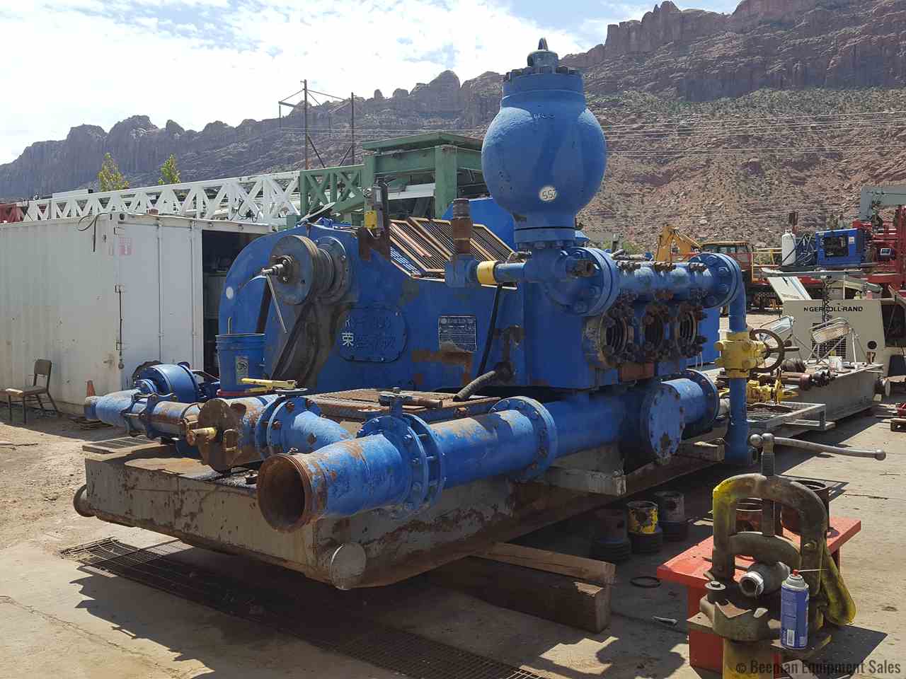
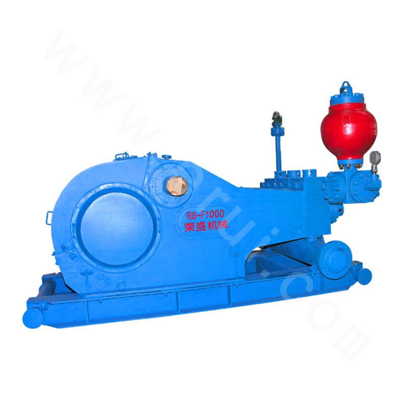
rs-f1000 mud pump free sample
Triplex pumps are positive-displacement reciprocating pumps that are configured with three plungers. They are the most common configuration of pump used in both drilling and well service operations. Triplex pumps used in well service activities generally are capable of handling a wide range of fluid types, including:
Triplex pumps are used in applications that require continuous pumping. For example, a triplex pump is a common component in large-capacity commercial car wash equipment. The plunger pump design of a triplex pump offers a reinforced seal and uses ceramic plungers for tight alignment and long life in high-pressure applications, such as oil well stimulation, surface preparation or rust removal, and gas turbine misting. Triplex pumps used in low-pressure applications also include a submersible liquid pump and an end-suction centrifugal pump. A submersible pump is typically constructed of stainless steel for corrosion resistance and can typically handle wastewater with suspended particles as large as 2 inches in diameter.
Triplex pumps are also suited to pump liquids other than fresh water or wastewater. They can be used to pump salt water in desalination applications, chemicals, and high vapor liquids like carbon dioxide. They can also be configured to pump mud in land-based or offshore oil drilling applications. A mud pump is a heavy-duty, high-pressure pump designed to provide a smooth discharge of mud and debris from oil wells. A triplex well pump can also be used as a well stimulation or servicing pump in oil fields and other industrial applications, such as cementing.
Industrial triplex pumps are used in public places that require a consistent water pressure with variable flow rates, such as hotels and office buildings, schools, hospitals, and in general industrial processes such as boosting the water supply for rural areas or municipalities or for irrigation. Because they are able to handle a wide range of fluid types, a triplex pump may also serve as a sump pump or in conjunction with other pumps to drain sump pits and wastewater storage lagoons.
Tom BS pump has been conpetely assembled and test operated under pressure before being shipped to the field. Unless otherwise instructed, the lubrication is drained from the power end. Before putting the pomp into serTice, the following precautions and operations mast be performed or checked.
The skid under the BS pumps are suitable for most any type of installation. It should be noted, however, that the box type construction of the power frame has high resistance to bending but relatively le b b resistance against twist. Therefore, the support under the pump must be level and adequate to support the weight and operating forces exerted by the pump.
In land installations, a mat of 76md x 305nn boards laid side crosswise to the pump skids for the entire length, or at a minimum, at the points indicated in Fig. 2, is usually sufficient. The boards should be a few feet nider than the width of the pump skid runners. Wet or marshy locations may require a more stable foundation.
On permanent installations such as barge, platform,structural base, or concrete slab, "where pump skids arebolted dowm, it is essential tkat the skids be properlyshinned to prevent possiblity of twisting or distortingthe power frame. The pump Bkids mast sit solid on allshim points with bolts loose.
On barge installations, tbe pump skids are generallybolted down to T-beams running parallel and in line withthe pump skids. Install shims at points shown in Fig, 2and 3 and observe caution of proper shinning to preventtwist or distortion. -
On installations where the power unit or electric motor is mounted integrally with the pump skids, the preferred installation wonld be to set the pump package on the T-beari skids and proTide retention blocks rather than bolts to hold it in place. This will allow the pinup to "float* and mininize the transfer of barge deck or platform distortion into the frame.
Adjust the belt tension by moving the sheares apart until all of the sag has just been eliminated from the tight aide of the belt and sane of the belta on the slack side. Then increase the centers approximately 13HJ (l/2 ") for each 254Gmm (100") center distance. Example: On 318Qnm (150*) center, move pump and additional 19. 5nm (3/4 *) .
The pump drive chain lubrication system on the majority of BS pomps is an independent system having I its own oil pomp, reservoir, and drive. Fill chain case to the indicated level with a non-detergent oil as follows: Ambient temperature abore 32° F (0*0) SAE-30 Ambient temperature aboTe 32° F (O"C) SAE-20
1. 06 kg. cm2) - Volume of oil being applied to chain. - Condition of nozzles in spray tube. - Condition of oil pump driTe (V- belts or chain)
NOTE: Oil pressure may be adjusted with the pressure relief adjusting screw on the rear of the pump housing. Pressure drops may also indicate suction and discharge filter screens need cleaning. t"
IndiTidual installation conditions will dictate the design of the suction system. The suction of the BS F- series pumps must hare a poeitire head ( pressure) for satisfactory performance. The optimum suction manifold pressure is 20- 30 psi (0.14 - 0. 2lMpa) for maximum Tolmnetric efficiency and expendable parts life. This head pressure is. best supplied by a 5 z 6 centrifugal pump with 40h. p 1150 rpm electric motor. This type of drite requires a derice to automatically start and stop the centrifugal pump motor simultaneously with the triplex pump. On DC electric powered rigs a signal can usually be supplied from the DC control panel to energize a magnetic starter when the mud pump clutch air line will proride a set of contacts for energizing the magnetic a- a
Under sane conditions the BS F- Series pumps may be operated without a charging pump, prorided the fluid level in mad pits is higher than the top of the liners, L fluid being pumped is low Tiscosity and suction line must be short, straight and of at least the same diameter as j suction manifold inlet.
The suction lines should be piped with Talve arrangementsso the charging pump can be by-passed bo operation can becontinued in eYent of charging pump failure or formaintenance. Operation without a charging pump can beimproTed by replacing the auction valve springs with aweaker spring. — ÿ
Do not pipe the return line from the shear relief valve Iback into the suction system as a relief TalTe operationwill cause a sudden pressure rise in the system vastly Igreater than the system pressure ratings, resulting indamage to manifold, suction desurger and centrifugal pump.
PREPARATION OF POWER ENDI Toox BS pump has been completely assembled and test operated before being shipped to the field. Unless otherwise instructed, the lubrication is drained from the r
power end, and the expendables are remored from the fluid end for storage protection. Before operating the pump, the following mast be performed or cheeked.nID 1. Power End Lubricat ion " J I
flush by remoring the pipe plugs on each side of the pump. Refer Item 2. Pig. .7.[I Add the proper type and quantity of lubrication in the power end. Refer to lubrication plate on pomp frame for type and quantity required.
Recheck oil lerel after pump has operated for a period of 15 minutes. Shut pump down and allow approximately fire minutes for the oil lerel to equalize. Check atH" oil leiel gauge, Item 1, Pig. 7. It is usuallyV necessary for a few more gallons of oil to be added due to a certain amount being retained in the croeshead area and frame caYitiea.
: } With reference to Figure 4A, remoTe the diaphragm stuffing box and plate (1) and rotate pump so that cr os ahead is at the front of the Btroke, Thoroughly clean the front of the crosshead and the face of the crosshead extension rod. Insert alignment boss on
Stationary spray type haie been used on BS F-series pumps Ref. Fig 5. It consists of a fixture (I), a pipe (2) and a spray nozzle (3), irhich applies cooling fluid in the form of a spray to the piston and liner area. Adjust cooling irater supply to the manifold so that a spray approximately 305nn long is being discharged from -each spray nozzle. Inspect spray nozzle operation rery often. making sure the nozzle is pointed directly at the piston.
Cooling fluid be thanfuaed from pump (Item 3. Fig. 6) and Water tank (Item 5 Fig 6) to the manifold on the frame. Adjust regulating TalTe (item 4 Fig. 6) to apply as much water as possible to the liners without splashing back on A-lfi nthe croaahead extension rods and diaphragm staffing" boxplate. 40L (lO-gallons) per minute per liner is thepreferred f low rate. If water is allowed to splash onthe croashead extension rods, some of the water will workback into the power end to contaminate the lubricationoil.
Install rear liner seal (5) and push into position against liner shoulder. Ref. Fig. 8. Slide liner cage (8) into fluid end, align one hole in the cage with lower valve pot bore. Set lower ralve guide (8) over ralve stem through lower hole in cage with the wings on the guide turned crosswise to the pump. Press downi0 A-20
on the" guide, compressing the valve spring (7) until the guide can be rotated l/4 tnrn and seat into place underneath the cage. Insert the lover Talve guide locking clip (9) through" the pad eyes on the lover valve guide and rotate dip to the right to lock the valve guide tight against the OD of the liner cage. It may sometimes be necessary to put more or less bend in the center of the clip to make it retain the guide tightly while the clip handle snaps into position on the right hand side. Cylinder Head & Insert the outer seal (5) in the fluid end bore against the liner cage. Slide the cylinder head plug (10) into fluid end. Apply a liberal coat of grease to both mating thread surfaces of the cylinder head (2) Screw- cylinder head in and tighten with wrench furnished with pump and sledge banner. Fluid leakage through the weep hole will indicate a defective seal or loose cylinder head. DO NOT plug weep holes as this can result in severe damage to sylinder head threads, thread rings, etc., in eTent of a liner seal failure.
Note: All of the parts in this fluid end assembly are designed with metal to metal seating to alleiiate friction wear from breathing action encountered in modern high pressure pump operation. For this reason it iB essential that all parts be clean and free of rust, nicks and burrs before being assembled.Liner Install wear plate seal (l) in counterbore of fluid end. Slide wear plate (2) oTer studs until it seats BS F-1300. BS F-160Q ASSEMBLY OF FLUID END PARIS @
The shear relief valve ( 3) is installed on the ! > discharge manifold for the purpose of protecting the ! pump from excessively high pressure overloads. The relief valve must be installed so that it will be directly exposed to the mud DO NOT POT ANY TYPE OP . SHOT OFF VALVE between, the relief ralre and the J manifold. Pipe the discharge side of the relief valve* directly into the mad pit with as few. turns in the line as possible. IT IS NOT RECOAENDED for the discharge Bide of the valve to be piped into the sue t ion line of the pump.
O Precharge dampener before .a tar ting up pump. Precharge pressure should not be more than 2/3 of the pomp discharge pressure, or a maximum of 4. fiMpa.
Proper lubrication of the moving parts in any piece ofmachinery is tie moat important single factor affectingits ultimate life. To obtain maximum trouble -freeservice life from the poorer end of the BS pranp, it isnecessary to perform routine maintenance care andinspections to insure the proper amount of CLEANlubricant is being provided.The F-Series pumps utilize the controlled flow oil bath splash and pressure system to lubricate the entire powerend. The type of pressure system prorided in each individual pump will govern the minimum SHI at which thepump can be operated, i. e. pumps which haTe pressure lubrication only to the main and pinion bearingst hare aminimum rated speed of 40 SPM Pumps in which pressurelubrication is provided to the main. pinion, andctosshead bearings and crosshead compartments may beoperated at a minimum Epeed of 25 SM proTided there isa* minimum of 0. 035Mpa (5PSI) oil pressure. .
CAUTION: The pressure lubricating system can be provided with an externally mounted oil pomp driren through V- belts or an internally mounted oil pump driven from the main gear. When an internally mounted oil pump is used, the direction of rotation of the pinion shaft must be as shown in Fig. 10. B-2 rfcf r
haiing to gbe attention to hole alignment. This permits the installation of croashead pins fraa either direction. For BS P-600 pump. Oil passage from the top of the crosshead guid compartment to the crosshead bearing is shown in Pig. 11A. Oil accumulates in the compartment over the crossheads. The oil runs through the oil passage, (1) ( 2) and crosshead pins oil passage (3), and on to the crosshead pin bearing. As noted, the duplicate set of passageways (3) in the crosshead pin permits the crosshead pins to be rotated without hating to gire attention to hole alignment. This permits the installation of crosshead pins from either direction.
The total pressure lubrication system, incorporating the oil pump for the BS F-series pumps, is shown in Figure 12 B-4 p
A pressure relief raWe (6) is mounted, to the manifold block (2) to keep excess pressure from damaging oil pump and drive. The relief ralre is preset at 0. 2.7I4pa (40 PSI) and mnst not be tampered with.
When installing the internally mounted oil pomp ( 9 Fig. 12), position pump so that the back face of the drive gear is flash and parallel with the edge of the main gear, and gear teeth haTe 0. 60~ 0. 9 tern backlash.
m Fig. 13 B-fi r fRef. Pig. 13, Adjust tit 7- be It drire (2) to a point where tie two halves of the belt can almost be "pinched* together between the thumb and fingers at the center of the driTe. Orertightening can cause premature failure of the pump.
Adequate lubrication of the moving parts is, as stated, the most important single factor affecting the ultimate service life of the pump, CARE AND MAINTENANCE of the system is the sole responsibility of the operator or cren to which it has been assigned, and the extent to which „ ~ this is applied will determine the amount of ,trouble-free - j service life that will be obtained. : !ÿ The lubricant recommendations shown below, on the name plate on the side of the pump, are the result of extensive field tests. Substitutions b hou Id be made only ill extreme emergencies.
ONCE EACH SIX MQtflUb, or more often if oil becomescontaminated with abrasive particles or corrosiTecompounds, drain and flash the oil reservoir ew lubricant.Oil drains are located on either aide of the pump frame.
During the flushing procedure, thoroughly clean the oiltroughs and the compartment in top of the crosshead guide.Also clean or replace the filter element in the airbreather cap and clean suction screen. Remove coyer s fronsettling chamber and purge out contaminants before addingnew oil.Routine inspection on condition of oil should be made ascondensation of moisture in the air, intrusion of mud,water or dirt, can necessitate a more frequent oil change.
A settling chamber is located in the forward area of thepower end f loor, Contamination in the oil splashed intothis area is allowed to settle out and should be drainedout of the pump through the clean out covers located onthe frame wall underneath the crosBhead inspection doors.
Once each month, remove clean out covers on both sides ofpump to drain contaminated oil from settling chamber.Approximately 15-gallons of oil will be lost; replenishthe main reservoir to compensate for the amount drainedout. I
2. Safety wires - Check safety wires on all bolts including the main bearing hold-down bolts and eccentric bearing retainer bolts, Replace any broken wires after retightening the bolts. Refer to crankshaft assembly section for bolt torque requirements. 3. Oil lines - Check all oil lines to insure they are intact and free of obstructions. Check oil pump suction hose for damage or flat areas.
6. Main gear and pinion teeth - Inspect the condition of the main gear teeth and pinion gear teeth for any indications of abnormal wear. During the initial break-in period, there will be some ; pitting on the face of the gear teeth. This isn referred to as "initial pitting* and is not harmful to the life of the gear. However, if routine inspection indicates the degree of pitting continues to increase,m immediately contact the pump manufacturer for a more thorough inspection of the gear.
Although the basic construction of the rarious sizes ofBSF pumps raries somewhat, they all haie one reryimportant detail in common roller bearings. A rollerbearing is a precisely built machine within itself;therefore, careful handling is required in order toobtain the long service life and high load carryingcharacteristics associated with anti-fr ication bearings.
The suction, flange has a standard thread connection (8" NPT for BS F-500, 10* NPT for BS F-800, 12* NPT for BS F-1000/l300/ 1600) and is custom made to match the companion flange on the pump suction manifold. The connection is sealed off by an 0-ring seal.
crankshaft is mounted in the pump frame, the running clearance in main bearings will require that a simultaneous Bet of dial indicator readings be taken at the end of the shaft and the face of the gear; the actual face runout at any point being I the difference between these readings.
b. Install the outer races of the eccentric bearingB (13) I and the outer race retainer ring ( 3) in the three eccentric straps. Outer race retainer ring must be positioned so that oil scoop ij at tie bottom when I pump ib at mid-stroke. frighten retainer bolts (4) to the following torque; safety wire heads.
In order to obtain a more precise fit between tie mainbearing housing and the frame bore on BS P-Series pumps,the installation procedures outlined below are to befollowed (Refer to Pig. 16)
NOTE: For BS F-800, BS F- 1000, BS F- 1300, BS F-1600 upper and lower croashead guides are NOT interchangeable. In these pumps, the guides are machined so that the lower guide places the
The croaaheada in the pumps can be installed through thefront (f laid end) or back end of the croaahead guide.Reference Fig. 18. ISA. When inatalling croaaheada, obaervethe following precantiona:
.Install the center croaahead first. Crosshead pin is installed through the top of the pomp by removing the inspection corer. Slide crosshead pin into bore bat do not seat taper until the crosshead pin retainer (2) Fig. ISA has been installed NOTE: If old crossheads are to be reused, inspect the sliding surfaces for *ear or scoring. If necessary, the crossheads may be Buitched to opposite sides of the pump and rotated 180° to proTide a smooth surface for the bottom of the crosshead The center crosshead can be rotated 180° and the crosshead pin installed from the opposite side of pomp.
4. If the center Line of the extension rod is more than 0. 381mn (0. 015 ") Io* in the diaphragm plate bore, shims should be inserted tinder the lower guide- to bring the extension rod back to center, provided there is ample clearance between the top of crosshead and upper crosshead guide. It is normal for the lower guide to wear more at the rear dne to heavier loading at this point because of the angle of the eccentric strap. It is permissable to shim the guides on a taper if it iB done accurately to proTide firm support for the guide. Do not shim guides to leas than 0. 50nrn (0.020*) clearance. Iiar.gft cmahead clearances ire acceptable due to characteristics of triplex pump operation, the crosshead pressure is always on the lower guide.
For many years, the fluid end of a pump iras considered anon-wearing part which did not cause any concern otherthan possible infrequent repairs or replacementsresulting from fluid cuts or washouts. However, thehigher pressures of the present-day drilling requirementshave resulted in higher stresses being imposed on thefluid end which, when combined with the corrosivecharacteristics of the drilling fluid, have resulted inthe demand that more and better maintenance be given tothe fluid end parts and pieces if a reasonable operatinglife is to be obtained.ÿ
b. Do not engage pump clutch when prime moTer is running at a high rate of speed To do so can cause undesirable shock loads against both power end and fluid end
d Do not operate the pump for an extended per.iod of time if a seTere fluid knock is present. e. Properly prepare fuHd end for storage. When pump is to be shut down or not operated for a period of ten days or more, it is reconmended that the fluid end parts such as liners, piBtons, rods, etc., be remoTed from the pump and the fluid end flushed out completely with fresh water. After a thorough flushing, apply grease or a rust preventative to all of the machined surfaces such as Talve pot cover threads, valve pot cover gasket surfaces, valve seats, liner bores, etc. the parts removed from the pump including liners, piston rods, etc., should of course be protected from the elements. This will not only extend the life of the fluid end through resistance to corrosion, bat will also protect the usable life still left in the expendable parts and maintain them in good condition C-2S
The fluid end assembly for these triplex pumps consists of three forged cylinder blocks, complete with valve pot covers and cylinder heads, a suction manifold, and a discharge manifold.
CiJW AH 8- - <3 fin OIY DESCRIPTION PART No. 1 ii. i 4 r b g c 1 1b p ( u - F B00 AH Jb003~U6. 01. 00 F-IOOO AHisnn.i-06. oi. 00 ] 1 2 1 Coppt* Tbf Aiiy 010 AH34001-06A. 03.00 AH33001 -06A. 01. 00 J 3 1 C o nn 4 c t o r AH36001-06A. 30 AH36001-06A. 30 ~1 4 Tb ( C 1 lap-Do u b 1 1 08 AH35003-06. 02. 00 (2) AH35003-06. 02. 00 (371 5 1 01 1 Pnmp M 1 g PUtt AH34007-06. 03 IH33009-06 01A. 00 1 6 Skin Si I AH33001-06. 06. 00 AH33I101-06. 06, 00 7 1 0 I! Pflap 2S 25 0 1 Co nn 4 c t o r NPT"/» AH36001-06A. 29 AH36001-06A. 29 1 9 1 PreiiTtrl Gln
For best results, dampener precharge pressure should be not more than 2/3 of pump discharge pressure. Maximum precharge 650 PSI.
ITEM >0. QTY DESCRIPTION PART NO. 1 1 | .A d » p t e r B a < i1 a ( AH33003-01 2 1 Flkls Tuber AH33003-02 3 1 Pliaftr S e » 1 AH33003-03. 00 4 - 1 Bo dr AH33003-04 5 1 I Planter Stca AH33003-05 6 1 -| Buaper AH33003-06 7 1 Ro 1 1 Pin AH33003-07 8 1 Carer Spr lit AH33003-08 9 1 Cerer AH33003-09 10 1 Shear Bar AH33003-10 11 1 Shear P Ia AH33003-11 12 1 ItralK Plate AH33003-1HB 13 1 Shear Bar Ptn AH33003-13 14 Retainer Rlnf AH33003-14 15 1 Nine P 1 (-1 e AH33003— 15A 16 1 Cutter Pitt 4X26 GB 9 1-8 6 17 Not M4 GB4-1-B6 18 C ip g cr ew M4X15 GB6-7-B5 1S 1 Belt "A-16UNCX47, T50-10 16 20 1 Nut V.-16UNC T51-1005 21 ! 1 C.pecre* M3XB GB67-B 6J I I PACXING LIST U foil bsf-iooo triplex: PUMPS I i l i I
Lake Petro can supply F series,3NB series,9-P-100/13-P-130/12-P-160 series, PZ7/8/9 series of drilling pump piston assembly metric (inch) with various sizes.
The piston rubber is also called the piston cup, its the expendable parts at the drilling pump hydraulic system, and it is one of the biggest wearing parts of drilling work.
Lake Petro can supply various mud pump expendable parts, including power end assembly, fluid end assembly and its spare parts, which can be easily matched & exchanged with some international famous mud pump brand, such as parts for 3NB series Pump, F series Pump, PZ series Pump, HBRS Pump, BOMCO Pump, EMSCO Pump, NOV P Series Pump, IDECO Pump, etc.

The 2,200-hp mud pump for offshore applications is a single-acting reciprocating triplex mud pump designed for high fluid flow rates, even at low operating speeds, and with a long stroke design. These features reduce the number of load reversals in critical components and increase the life of fluid end parts.
The pump’s critical components are strategically placed to make maintenance and inspection far easier and safer. The two-piece, quick-release piston rod lets you remove the piston without disturbing the liner, minimizing downtime when you’re replacing fluid parts.
SCOPE This specification covers the preservation and storage procedure for shipment of new-build NOV Triplex Mud Pumps shipped from the manufacturing plant. This specification is intended to provide preservation of new-build NOV Triplex Mud Pumps for six (6) months from the shipment of the mud pump from the manufacturing facility. If a pump is to be stored for a period of time exceeding six (6) months, additional precautions should be taken as outlined in this specification. National Oilwell Varco recommends that all pumps are inspected for any signs of corrosion and for proper preservation at a minimum every three (3) months for pumps stored outside and every six (6) months for pumps stored indoors. Sub-tier: National Oilwell PS-3081
MANUFACTURING PLANT PRESERVATION PRIOR TO PAINT Drain all water and clean out liner wash tank. Remove drain plug in bottom of liner wash pump and drain water then reinstall plug. Remove discharge flange from liner wash pump and pour one (1) pint of inhibiting oil-based concentrate (Cortec VpCI 329 Vapor Corrosion Inhibiting oil-based concentrate or equivalent) into liner wash pump. Rotate two (2) revolutions by hand to distribute the product. Re-install discharge flange. Drain all oil from pump power end sump and remove crosshead covers and inspection covers. Clean out oil sump as per National Oilwell PS-3081 (Mud Pump Cleanliness). Spray all internal machined parts of power end and crosshead area with inhibiting oil-based concentrate (Cortec VpCI 329 Vapor Corrosion Inhibiting oil-based concentrate or equivalent). Rotate pump ½ turn and re-spray. Pour quantity of inhibiting oil-based concentrate specified in the table below into power end sump. Mud Pump Models
For pumps equipped with chain drives, spray internal machined parts inside chain cases with inhibiting oil-based concentrate (Cortec VpCI 329 Vapor Corrosion Inhibiting oil based concentrate or equivalent).
MANUFACTURING PLANT PRESERVATION AFTER PAINT Remove breather and pack with loose parts for later shipment with pump. Seal breather hole with a greased solid plug. Affix a warning label near the breather opening (see Exhibit 1). Spray all external unpainted machined parts of pump with rust preventative (CRC SP400 or equivalent). Cover large diameter pipe and other openings with hardboard and protective plastic wrap. Liner bushing openings shall also be covered and sealed. Seal all other pipe work (air, water, and electrical) with plastic caps of the correct size and style. Electrical J-boxes are to be encased in protective plastic wrap. Place two (2) onepound bags of desiccant inside each J-box before sealing with tape. Wrap pressure gauges with bubble paper and plastic. Tape or band down loose hinged guards and inspection covers. Spray all machined unpainted loose parts and expendables to be shipped with pump with rust preventative (CRC SP400 or equivalent). All parts will be wrapped or boxed to prevent damage. Affix one (1) warning label (see Exhibit 2) to the power end pump cover and one (1) warning label on the fluid end assembly of the pump. Affix warning labels on each loose part container. In cases where the equipment will be boxed at an offsite export packer, a sufficient number of warning labels will be supplied with the shipment.
STORAGE AT MANUFACTURING PLANT OR FINAL DESTINATION Indoor storage is preferred whenever possible; but if outside storage is required, ensure pump is stored away from salt water spray, sand blast or other adverse conditions. It is highly recommended that ship loose parts be stored indoors to eliminate conditions that promote condensation and direct sources of moisture. It is also recommended to store pump on blocks and cover entire pump with plastic sheeting.
PRESERVATION PROCEDURE WHEN STORAGE EXCEEDS SIX (6) MONTHS OF INITIAL PRESERVATION. Note: It is recommended that inspections be carried out on six (6) month cycles when pumps are in indoors and three (3) month cycles when stored outside. Remove plastic sheeting. Remove side crosshead covers and top inspection covers and inspect for any internal corrosion. Correct any adverse conditions. Replenish rust inhibitor to quantities previously listed. Rotate pinion shaft five (5) revolutions using supplied tool. Inspect for condition of external protection (rust preventative and paint). adverse conditions.
START-UP AFTER STORAGE Any pump that has been in storage will need a thorough inspection prior to start-up to insure it has not been damaged in any way and that all parts are properly in place. Failure to observe the following points can result in serious damage. Before servicing the pump, the power end sump and chain drives housings will need to be drained of any inhibiting additive. The Cortec brand products used for preservation are compatible with all lubricating oils and need not be totally removed when putting equipment into service. To service the Power End after storage and prior to start-up, remove all covers and thoroughly clean and inspect all of the parts and finished surfaces. Check all of the bearings to make certain they are clean and in good condition. Fill the power end with clean EP oil of the proper viscosity to the proper level. Make sure oil is poured into the oil distribution trough and is worked into all of the bearings. Replace all covers and install breather. To service the Fluid End after storage and prior to start-up, remove covers and thoroughly clean and inspect inside of the fluid end cylinders. Properly install valves, pistons, liners and all other fluid end parts. Carefully tighten all bolts, nuts, studs and working connections to specified torque requirements.
Pre-Start Up Requirements..................................................................................... 1. Power End.................................................................................................. 2. Main Electric Drive Motors……………………………………………… 3. Auxiliary A/C Motors……………………………………………………. 4. Instrumentation........................................................................................... 5. Liner Wash System..................................................................................... 6. Fluid End.................................................................................................... 7. Suction Dampener/Desurger....................................................................... 8. Pulsation Dampener.................................................................................... 9. Pressure Gauge............................................................................................ 10. Reset Relief Valve....................................................................................... 11. Discharge Strainer………………………………………………………… 12. Mud Pump Drive Assembly………………………………………………. a. Belt Drive Units…………………………………………………… b. Chain Drive Units………………………………………………….
INITIAL STARTUP PROCEDURES GENERAL: The initial startup procedures are written to assist the operator in preparing the pump packages for normal operation. The startup procedures are separated into two categories: Part I: Pre-Commissioning, and Part II: Commissioning Procedures. It is suggested that a copy of these pages be made for each pump to be used as a check-off sheet.
Reservoir Capacity: 100 US Gallons (379 Liters) Note: The rust preventative on the internal surfaces of the pump is oil-soluble and is compatible with the lubricants recommended above. It is not necessary to flush and drain unless the preservative has become contaminated (water, sand etc.). b. Oil Filters: Assure that the oil filters in the power end reservoir and external oil pump system are clean. 2. Main Electric Drive Motors:
Clean liner wash tank, if needed, and fill with fresh clean water. Ensure that supply hoses and spray nipples are installed correctly. Start pump and adjust regulating valve to maximum flow without splash onto the extension rods.
NOTE: When charging the bladder, make sure that the mud pump suction line valve has been closed and that all pressure has been bled off of the suction manifold surrounding the suction desurger
If a dampener is used, charge dampener with a hand-operated air pump to 10 PSI (0.7 bar). Once pump operations have been started, check the operation of the suction dampener by inspecting the sight glass. Add or release air pressure through the Shraeder valve to keep the diaphragm between the midpoint and the bottom of the sight glass.
Check the installation and the setting. NO SHUT-OFF VALVE is to be between the pump discharge and the relief valve. Ensure that piping from the discharge port goes directly to the mud tank/pit and is securely tied down, with a minimum downward slope of 1/4” per foot. Ensure that piping has pressure rating equal to the relief valve highest setting.
Check the chain guards to ensure that the chains will not drag on the guard. Check the oil pump to ensure that the relief valve is installed on the suction side. Start the pump and ensure that the spray nozzles are spraying oil over the full width of the chain. Adjust the relief valve to 15-25 PSI output with the warm oil.
PART II. COMMISSIONING PROCEDURES: GENERAL: The power end and the fluid end have gone through rigorous tests prior to being shipped from the manufacturing site; therefore, the following recommendations for the commissioning test are made for the purpose of checking the overall unitization functions, including instrumentation, and to assure that there are no problems which may have occurred during transportation and storage. Operation of the pump in parallel to check the SCR-Motor assignments and controls, volumetric displacement and mudline systems are at the option of the purchaser. A. PRE-COMMISSIONING CHECKS: Prior to starting the unitized pump package, review the previously outlined Pre-Commissioning Requirements in Part I. Check the discharge mudline to assure that all necessary valves are open. Ensure that the mud tanks are full of test fluid (mud/water) prior to startup. Make the desired assignment of the SCR-Motor Control System to the pump motors, and open the throttle slightly. Check to ensure that charge pump and liner wash motors have started. If no immediate problems are encountered, slowly throttle the pump to approximately 60 SPM and continue operating the mud pump while making the following inspections to assure that all systems are working properly: 1) Power End Lubrication: Check oil pressure:
5) Visually inspect the mud pump drive assembly for any unusual conditions, i.e. loose bolts, vibration, noise, etc. 6) Check the performance of the supercharging system:
Check the valve for proper relief setting. The valve should be set 10% above the pressure rating for the liner size being used. Refer to the nameplates on each side of the pump or the pump datasheet to obtain the operating pressure for that particular size liner.
B. COMMISSIONING OPERATIONAL TEST: DURATION: EIGHT (8) HOURS TOTAL RUNNING TIME. The following are basic guidelines for conducting of an eight (8) hour operational test. The pump was test run under pressure in the manufacturing plant but with different motors and drives. The discharge pressure can be regulated by temporarily installing an adjustable choke at some point in the discharge line. NOTE: There can be short intervals of shut-down time to fix leaks, make adjustments, etc., without having to restart the test program. 1. LOWER PRESSURE TEST – DURATION: TWO (2) HOURS: TIME START STOP 0-500 PSI (0.34-34.5 bar)…………………40 min. @ 40 SPM
C. INSPECTIONS/CHECK-OFFS DURING TEST PROGRAM: The overall performance of the unitized pump package should be continuously monitored during the eight hour test program. The following checks should be made and recorded each two hours of operation. START
INSTALLATION OF NEW PUMP Your National Oilwell Varco pump has been completely assembled and test operated under pressure before being shipped to the field. Unless otherwise instructed, the lubrication is drained from the power end and the expendable parts are removed from the fluid end. Before putting the pump into service, the following precautions and operations must be performed or checked. In order to prevent personal injury during the performance of any maintenance or inspection procedures, this equipment MUST BE SHUT DOWN AND NOT OPERATING, and all safety devices on prime movers, drives, etc., MUST BE IN THE SAFE POSITION.
SETTING THE PUMP The skids under the National Oilwell Varco pumps are suitable for most any type of installation. It should be noted, however, that the box type construction of the power frame has high resistance to bending but relatively less resistance against twist. Therefore, the support under the pump must be level and adequate to support the weight and operating forces exerted by the pump.
Land Installations In land installations, a mat of 3” X 12” (76.20 mm x 304.8 mm) boards laid side crosswise to the pump skids for the entire length, or at a minimum, at the points indicated in Fig. 2, is usually sufficient. The boards should be a few feet wider than the width of the pump skid runners. Wet or marshy locations may require a more stable foundation.
Fig. 2 Suitable means, such as National Oilwell Varco pump spacers as shown in Fig. 3, should be used to keep the pump anchored and the drive in alignment. National Oilwell Varco mud pump spacers provide 8-1/2” (215.9mm) adjustment. Any desired length may be obtained by lengthening the standard pipe spacer, which is made of 3” (76.20mm) extra strong pipe. Three types of attaching heads are available with this spacer:
2.1.1 Permanent Installations On permanent installations such as barge, platform, structural base, or concrete slab, where pump skids are bolted down, it is essential that the skids be properly shimmed to prevent possibility of twisting or distorting the power frame. The pump skids must sit solid on all shim points with bolts loose. On barge installations, the pump skids are generally bolted down to T-beams running parallel and in line with the pump skids. Install shims at points shown in Figs. 2 and 4 and observe caution of proper shimming to prevent twist or distortion. The shims on all installations should extend the full width of the skid beam flanges and have a minimum length of 12” (305mm). On installations where the power unit or electric motor is mounted integrally with the pump skids, the preferred installation would be to set the pump package on the T-beam skids and provide retention blocks rather than bolts to hold it in place. This will allow the pump to “float” and minimize the transfer of barge deck or platform distortion into the frame. 2.1.2 Installation of the Drive The drive between the mud pumps and the power source, whether V-belts or multi-width chains, should be installed with the greatest care to assure maximum operating life with minimum of unexpected or undesirable shutdowns due to drive failures. When installing the drive sheave or sprocket, make sure all grease or rust preventative is removed from the shaft and the bore of the drive. Remove all burrs or rough spots from the shaft, key, and keyway. Fit key to the keyways in both the shaft and drive and install key into shaft keyway. Coat pinion shaft with a light coating of anti-seize compound or light oil and install the drive sheave or sprocket hub. Tighten hub bolts as indicated below:
Adjust V-belts for proper tension. Adjust the belt tension by moving the sheaves apart until all of the sag has just been eliminated from the tight side of the belt and some of the belts on the slack side. Then increase the centers approximately ½” (13mm) for each 100” (2540 mm) center distance. Example: On 150” (3810 mm) center, move pump an additional ¾” (19.5 mm).
DO NOT OBTAIN BELT TENSION BY PICKING UP END OF PUMP AND ALLOWING BELTS TO TIGHTEN UNDER WEIGHT OF PUMP AS END IS BEING LOWERED TO THE GROUND. 2.1.2.2 Chain Drives a. Installation Proper installation and maintenance of the sprocket and chain drives are essential if good service life is to be obtained. Since many factors, such as chain width, center distances, speeds, and loads must be considered when determining the allowable tolerance for sprocket alignment, no good “rule of thumb” can be applied. The chain alignment must simply be held as nearly perfect as possible. A more precise alignment can be made by stretching two steel wires (piano wire) along one face of the two sprockets, one above and one below the centerline, and moving one of the sprockets until the wires touch at four points. This will determine that the centerlines of the drives are parallel and the faces of the sprockets are square. b.
Drive chain lubrication The pump drive chain lubrication system on the majority of National Oilwell Varco pumps is an independent system having its own oil pump, reservoir, and drive. Fill chain case to the indicated level with a non-detergent oil as follows: Ambient temperature above 32°F (0°C) SAE-30 Ambient temperature below 32°F (0°C) SAE-20 For temperatures below 0°F, consult a reputable lubrication dealer for recommendations. REFER TO GENERAL LUBRICATION BULLETIN for approved lubricants and additional specifications. If any discrepancy exists between the recommendations in this manual and the General Lubrication Bullletin, those in the Lubrication Bulletin will take precedence. Since this is an independent system, it will require the same maintenance or service attention employed on any other piece of machinery, including: - Daily check of oil level. - Daily check on condition of oil. - Frequent check on oil pressure. (5-15 psi) (.352 - 1.06 kg/cm²) - Volume of oil being applied to chain. - Condition of nozzles in spray tube. - Condition of oil pump drive (V-belts or chain)
NOTE: Oil pressure may be adjusted with the pressure relief adjusting screw on the rear of the pump housing. Pressure drops may also indicate suction and discharge filter screens need cleaning. 3
SUCTION SYSTEM REQUIREMENTS Individual installation conditions will dictate the design of the suction system. The suction of the FD-series pumps must have a positive head (pressure) for satisfactory performance. The optimum suction manifold pressure is 20-30 psi (1.75-2 kg/cm²) for maximum volumetric efficiency and expendable parts life. This head pressure is best supplied by a 5 x 6 centrifugal pump with 40 h.p. 1150 rpm electric motor. This type of drive requires a device to automatically start and stop the centrifugal pump motor simultaneously with the triplex pump. On DC electric powered rigs a signal can usually be supplied from the DC control panel to energize a magnetic starter when the mud pump clutch air line will provide a set of contacts for energizing the magnetic starter when clutch is engaged. The charging pump can also be belt driven from the triplex pinion shaft charging type of drive is not as efficient at slow speeds with viscous fluids. Under some conditions the FD-Series pumps may be operated without a charging pump, provided the fluid level in mud pits is higher than the top of the liners, fluid being pumped is low viscosity and suction line must be short, straight and of at least the same diameter as suction manifold inlet. The suction lines should be piped with valve arrangements so the charging pump can be by-passed so operation can be continued in event of charging pump failure or for maintenance. Operation without a charging pump can be improved by replacing the suction valve springs with a weaker spring. Suction desurgers are a very effective aid for complete filling of the liners and dampening pulsations in the suction line which results in a smoother flow in the discharge line. If your pump is equipped with a suction desurger it must be pre-charged with compressed air before operations are begun. See suction desurger manual for charging instructions.
Caution Do not pipe the return line from the shear relief valve back into the suction system as a relief valve operation will cause a sudden pressure rise in the system vastly greater than the system pressure ratings, resulting in damage to manifold, suction desurger and centrifugal pump.
PREPARATION OF POWER END Your National Oilwell Varco pump has been completely assembled and test operated before being shipped to the field. Unless otherwise instructed, the lubrication is drained from the power end, and the expendables are removed from the fluid end for storage protection. Before operating the pump, the following must be performed or checked:
Power End Lubrication Before installing lubricant, open inspection door in cover and check oil reservoir for possible accumulation of condensation, etc., and drain and flush by removing the pipe plugs on each side of the pump. Add the proper type and quantity of lubrication in the power end. Refer to the Lubrication Section of this manual, or lubrication plate on pump frame for type and quantity required. Recheck oil level after pump has operated for a period of 15 minutes. Shut pump down and allow approximately five minutes for the oil level to equalize. Check at oil level gauge, Item 1, Fig. 1. It is usually necessary for a few more gallons of oil to be added due to a certain amount being retained in the crosshead area and frame cavities.
With reference to Figure 5, remove the diaphragm stuffing box and plate (1) and rotate pump so that crosshead is at the front of the stroke. Thoroughly clean the front of the crosshead and the face of the crosshead extension rod. Insert alignment boss on crosshead extension rod into the crosshead bore and tighten the retainer bolts (2) to the following torque. Safety wire bolt heads. FD-500 50-60 ft. lbs. (7-8 meter kgs) FD-800 80-100 ft. lbs. (11-14mkgs.) FD-1000 350-370 ft. lbs. (48-51 meter kgs) FD-1600 350-370 ft. lbs. (48-51mkgs.) Thoroughly clean face of power frame and diaphragm stuffing box plate at Position “A”. Install gasket (3) and capscrews (10). Tighten capscrews as follows: FD-500 12-14 ft. lbs. (1.7 - 1.9 meter kgs)
Two types of piston and liner cooling systems have been used on National Oilwell Varco FD-Series Pumps -- the stationary spray type and a moving nozzle type. Ref. Fig. 6. The manifold (1) for supplying cooling fluid to the piston and liner assemblies is identical on both systems. Cooling fluid from either a remote source such as a water line, or from a pump and reservoir system unitized on the pump skids (Ref. Fig. 7) must be piped into the manifold at the connection located in the pump frame under the crosshead extension rod section. CAUTION:
With reference to Fig. 7, maintain electric motor (1) and centrifugal pump (2) according to manufacturer’s specifications. Rotation of the pump should be clockwise when viewed from the impeller end. Adjust regulating valve (3) to apply as much water as possible to the liners without splashing back on the crosshead extension rods and diaphragm stuffing box plate. 10gallons per minute per liner is the preferred flow rate. If water is allowed to splash on the crosshead extension rods, some of the water may work back into the power end to contaminate the lubrication oil.
Liner Cage and Lower Valve Guide Install rear liner seal (5) and push into position against liner shoulder. Slide liner cage (6) into fluid end, align one hole in the cage with lower valve pot bore. Set lower valve guide (8) over valve stem through lower hole in cage with the wings on the guide turned crosswise to the pump. Press down on the guide, compressing the valve spring (7) until the guide can be rotated ¼ turn and seat into place underneath the cage. Insert the lower valve guide locking clip (9) through the pad eyes on the lower valve guide and rotate clip to the right to lock the valve guide tight against the OD of the liner cage. It may sometimes be necessary to put more or less bend in the center of the clip to make it retain the guide tightly while the clip handle snaps into position on the right hand side.
Cylinder head Insert the outer seal (5) in the fluid end bore against the liner cage. Slide the cylinder head plug (10) into fluid end. Apply a liberal coat of grease to both mating thread surfaces of the cylinder head (2). Screw cylinder head in and tighten with wrench furnished with pump and sledge hammer. Fluid leakage through the weep hole will indicate a defective seal or loose cylinder head. DO NOT plug weep holes as this can result in severe damage to cylinder head threads, thread rings, etc., in event of a liner seal failure.
Figure 9B A cross section through the fluid end is shown in fig. 9B. With reference to fig. 9B thoroughly clean and assemble the fluid end parts in the following manner: Note: All of the parts in this fluid end assembly are designed with metal to metal seating to alleviate friction wear from breathing action encountered in modern high pressure pump operation. For this reason it is essential that all parts be clean and free of rust, nicks and burrs before being assembled.
Liner Install wear plate seal (1) in counterbore of fluid end. Slide wear plate (2) over studs until it seats against fluid end. Slide liner thread ring (3) over studs with the starting thread at the 5 o’clock position and tighten nuts to 470-510 ft. lbs. (65-70 m/kgs.) torque. Note: Placing the starting thread at 5 o’clock position makes engaging the liner lock threads much easier. Place liner seal (4) in counterbore of wear plate. Apply thin coat of grease to ID of liner lock (5) and slide over rear of liner (6). Install two-piece liner lock ring (7) in liner groove and “O” ring to hold them in position. Slide liner handling tool over liner up against liner lock ring and tighten set screw to secure it in place. Hoist liner assembly into position with jib hoist. Note: FD pumps are factory equipped with jib booms and liner handling tools. If older pumps are converted to FD fluid ends a jib boom should be added to the pump frame as considerable weight is involved in handling the liner assembly. Apply liberal coat of grease to liner lock threads. Align the starting thread of the liner lock (5) to the 7 o’clock position and insert the liner into the liner thread ring (3) screw liner lock in until liner seats in position . Tighten with sledge hammer on hammer lugs.
Suction Flange The suction flange has a 12” (305mm) standard pipe thread connection and is custom made to match the companion flange on the pump suction manifold. The flange connection is sealed off by an O-ring seal (14” OD x 13-1/2” ID x ¼ “), (356mm OD x 343mm I.D. x 6.35mm Dia.) NOTE: Thoroughly clean O-ring groove and face of flanges before making up connection. Flanges must make up metal to metal to insure proper seal. Tighten flange bolts to 360490 ft. lbs. (50-68 meter kgs.) torque. CAUTION: If suction pipe is welded to suction flange, remove O-ring prior to welding.
Accessory Manifold Fig. 10 is not the standard discharge arrangement on the model FD-1600 pump, which uses the strainer cross configuration. An accessory manifold, Fig.10, is available for installation on the discharge manifold opposite the discharge end. The manifold will accommodate a discharge pulsation dampener (1) and provides two 3”-6000 PSI*side outlet connections for such items as a pressure gauge (2) and a shear relief valve (3). When manifold is used, install and maintain as follows:
The flange on the accessory manifold is a 5”-1500 *RTJ. Thoroughly clean ring joint groove, install ring (4) and tighten the flange bolts (5) to 1200 ft. lbs. torque. To assure uniform make-up of the ring joint connection, tighten the nuts in a criss-cross order. The shear relief valve (3) is installed on the discharge manifold for the purpose of protecting the pump from excessively high pressure overloads. The relief valve must be installed so that it will be directly exposed to the mud. DO NOT PUT ANY TYPE OF SHUT OFF VALVE between the relief valve and the manifold. Pipe the discharge side of the relief valve directly into the mud pit with as few turns in the line as possible. IT IS NOT RECOMMENDED for the discharge side of the valve to be piped into the suction line of the pump. * 5” -
3” - 6000 PSI = two 76.2mm - 422 kg/cm² The relief valve setting should be just above the maximum pressure rating of the particular liner size being used. CHANGE SETTINGS with each liner size change. DO NOT USE ALLEN WRENCHES, WELDING RODS, or material other than that called for by the manufacturer of the relief valve, as this will affect the rating of the relief valve. The mounting for the dischage pulsation dampener (1) is a RTJ flange with R-39 ring gasket. Before installing dampener, thoroughly clean ring groove and ring, and after setting dampener into place, tighte


 8613371530291