
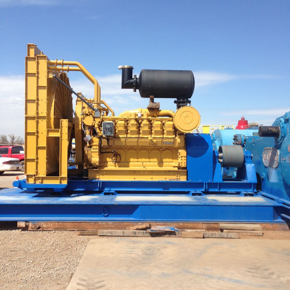
run mud pump with one geneator and old scr house price
ENSCO 71 is a Jack-Up drilling rig which was originally constructed at the Hitachi Zosen shipyard in 1982. The original GE motor controls comprised five 1163 KVA generators and four 1800 ADC SCR units with associated auxiliary transformer feeders and jacking units. The SCRs were assignable to two 1600 HP twin-motor Mud Pumps, a twin motor 2000 HP Drawworks and a 1000 HP Rotary Table. A separate feeder drives a 1110 HP Top Drive. A fifth SCR was added by Hill Graham Controls in 1985 to power a third 1600 HP Mud Pump, which was cabled to the main busbars.
In early 2012, a decision was made to add a fifth 2500 KVA generator and an additional auxiliary transformer, to close-couple these to the main switchboard via a bus tie circuit breaker, and to include a dedicated feeder for the fifth SCR. A sixth SCR was also included in the switchboard extension to provide an alternative drive source for the third Mud Pump, effectively removing this load from the main switchboard. The switchboard extension, including full integration with the existing GE and Hill Graham equipment, was engineered and built by Zeefax.
As well as providing an extension to the main 600 V switchboard, Zeefax also designed, built and commissioned an accompanying 480 V switchboard comprising of an incoming circuit breaker and a number of small moulded case distribution circuit breakers.
The design and engineering process involved completing a detailed Power Studyto examine the consequences, in terms of fault rating, of adding the new equipment. Various scenarios were considered, and the financial impact was assessed to determine the most cost effective interconnection configuration. As a result of the study the amount of upgrade work required on the existing equipment was minimised.
The Power System Study was completed by gathering data about the existing switchboard arrangement and comparing this to the original, hand written, fault level calculations. The new calculations were performed using software modelling and verified to IEC 61363. The IEC 61363 Short Circuit study represents conditions that may affect typical marine or offshore installations more significantly than land-based systems, including more emphasis on generator and motor decay. This confirmed the original calculations were accurate.
As well as considering the effects of fault currents, Zeefax also completed a complete protective device co-ordination study to confirm and ensure that proper co-ordination was established for all operating scenarios. This included the existing equipment as well as the components in the switchboard extension, and the new 480 V switchboard and transformer.
Finally, the study also included calculating the strength and current-carrying capacity of the busbars under normal and fault conditions to establish the correct busbar sizes and bracing.

We’ve been in a flurry of activity this year, crushing out upgrades on over thirty rigs selected for our 2017 Rig Upgrade Program. Most recently, our team in Nisku, Alberta cut the tape on the new-and-improved Rig 44, which was upgraded from a 750 HP SCR to a 1,000 HP AC-powered heavy telescopic double.
Proudly boasting “first-of-its-kind” status in our Canadian fleet, the rig and its crews were turned loose in the Montney Basin for the first time this week since the upgrade.
The combination of Rig 44’s high hook load, AC-power, 1,600 HP direct-drive mud pumps, and 7,500 PSI circulating system make it unique to our Canadian fleet. It’s also equipped with bi-fuel engines and a walking system capable of moving the rig with full setback (meaning the drill pipe is left in the derrick during the move).
Want to see more of our 2017 upgrades in action? Check out Trinidad Rig 100, the first ever rig in our US fleet, with its new 1,000,000 lb. hook load, walking system, 25,000 foot racking system with 5 inch drill pipe, and 7,500 PSI capabilities.

The SCR Drive Assignment Contactors are fitted in the armature and are actuated by Allen Bradley PLC logic; through Allen Bradley flex I/O located in the SCR drive bay. The flex I/O communicates through a dual loop Profibus configuration to a processor for the first five SCR bays and a second matching configures for the next five SCR bays. The assignment configuration is such that any motor is assignable in three locations with any motor capable of assigning to the first five SCR bay or the second set of five SCR bays.
Each drive can support 4 different motor parameter sets. All the SCR Drives on the Frontier Driller shall be configured accordingly to the motors that they will support.
This architecture offers flexibility and reliability through redundancy in case of SCR drive failure. Should such an event occur the operator simply turns off the motor on the faulted SCR drive and turns back on allowing the PLC to assign to the next available SCR drive. Each motor is assignable to three different SCR drives with a total of twenty (20) SCR drives in the system.
The SCR Drives are controlled from consoles via profibus loop circuit to the dual redundant Logix 5561 CPU Allen Bradley PLC system. Overview of the SCR distribution with SCR PLC.
By use of the dual 5561 Allen Bradley processor (CPU) in the PLC system either processor can fail with no loss of operation. Communications to the drives is done by Profibus loop directly to the Siemens 6RA70 and flex I/0 locate each SCR bay. The flex I/O receives input and from devices outside the drive such as armature contactor feedback, drive cooling fan overload, circuit breaker status and the OFF/DRILL/MARINE selector switch. The flex I/0 receives output commands outside of the 6RA70 control for contactor assignments. The Siemens 6RA70 SCR drive sends and receives data as per the supplied manual, which controls operation of the motor and gathers operating information for logic control. All control signals from SCR to PLC shall be communicated through PROFIBUS DP field bus protocol, with the exception of the Emergency Stops, which shall be hardwired directly to the SCR Drive breaker for safety.
Signals exchanged between an SCR and its respective PLC are the same for each SCR. Apart from standard control/status signals, signals related to assignment and power management need to be exchanged.
This architecture offers flexibility and reliability through redundancy in case of PLC or communication failure. Should such an event occur, the communication cable could with stand one break in any loop and complete failure of either PLC1-A or PLC1-B with no loss of operation.
There is a PROFIBUS DP communication network for each SCR drive to the two PLC racks located in the generator cubicles. Each network is completely independent from the other with communications that are loop and able to be controlled by either CPU. The PLC racks located in the Driller’s Console and in the Mud Pump Console are networked by Ethernet Fiber optic loop to a MOXA module to convert the fiber signal. The two screens in the driller’s console are networked on this same loop with both screens able to display the same screens and status. There are two more MOXA modules connected in the same loop to supply data to the two workstations to enable data collection and trouble shooting of the complete system. There are two more MOXA modules on the same loop connected to PLC3A and PLC3B in the field supply cabinets, which in turn are connected to all the MCC, by Profibus fiber optic loop for control and status of all the required motor starters. Overview of the SCR PLC PROFIBUS DP and Ethernet communication network.
The PROFIBUS DP network in this application is based on 3 different mediums and topologies. A standard bus or line topology network with standard PROFIBUS DP RS-485 cable is established between an SCR PLC and its respective SCR drives. Each SCR is fitted with a CBP2 PROFIBUS communication board. Each one has its own address to differentiate between the various SCR Drives on the network. A redundant optical ring topology is established between all PLC racks via MOXA hub modules to form the Ethernet network. The third communication loop is Profibus fiber optic to all the Hirschmann Hub modules in the MCCs and the same type loop collecting data from the generator controls. MOXA modules and Hirschmann hub modules convert electrical signals to optical signals.
As of July 2007 we have completed the manufacturing portion of this project and have started testing the communications of the 5 remaining SCR Drive bays along with the Generator bays, Driller’s Console, Mud Pump Console & SCADA System. We have already shiped 5 DC drive bays and 1 of the 2 Isolation Switch bays and will ship the remaining equipment after completion of testing and DNV approvals.

Modern drilling techniques require additional equipment not found on older drilling rigs. Existing power systems can be modified by Advanced Control Systems in the field to accommodate the addition of Top Drives, Generators, Mud Pumps, and Independent Rotary Tables.
Obsolete SCR / Engine-Generator Control Systems can be economically retrofitted, refurbished or replaced altogether to increase dependability and decrease downtime.

- Cellar jet constructed of 6" OD pipe with 2" NPT x 3/4" orifice jet nozzle nipple installed in 90° long radius ell. 6" line runs from cellar bottom
- Air Compressors for 535 CFM at 145 psi/1MPa each equipped with dual controls, including pipes valve fitting and two air receiver tanks of 600 gallons.

By using this site, you are agreeing to security monitoring and auditing. For security purposes, and to ensure that the public service remains available to users, this government computer system employs programs to monitor network traffic to identify unauthorized attempts to upload or change information or to otherwise cause damage, including attempts to deny service to users.
Unauthorized attempts to upload information and/or change information on any portion of this site are strictly prohibited and are subject to prosecution under the Computer Fraud and Abuse Act of 1986 and the National Information Infrastructure Protection Act of 1996 (see Title 18 U.S.C. §§ 1001 and 1030).
If a user or application submits more than 10 requests per second, further requests from the IP address(es) may be limited for a brief period. Once the rate of requests has dropped below the threshold for 10 minutes, the user may resume accessing content on SEC.gov. This SEC practice is designed to limit excessive automated searches on SEC.gov and is not intended or expected to impact individuals browsing the SEC.gov website.
REVISION HISTORYRev. A B C D E F G H J K Description Initial Release Added Revision History page and drawing number in footer. Revised figures 1-10, 113, and 1-14. Formatting corrections. Corrected text and figure item callouts items in figures 1-4, 1-5, and 1-6. Make formatting correction. Remove references to ARH and Ansaldo Ross Hill on pages 1-1, 1-2, and 1-25. Update figures. Update (2) photos (Figure 1-5, Figure 1-9); add photo numbers; update figure number style. Revise Figure 1-1 to reduce printing time and printer memory problems. Convert to Word 97 format. Add Table of Contents codes. Correct Level 5 and Level 6 styles and errors. ERO/ECN # 041251 C23375 C24068 C24394 C24670 C25368 C25939 C26330 C28670 C29222
SCR DRIVE SYSTEMSYSTEM INFORMATIONDESCRIPTIONThe SCR Drive System provides electrical power conversion and control for the DC motors on a drilling rig. The system regulates AC power from engine-generator sets and delivers continuously variable DC power to traction motors which are coupled to functions such as Drawworks, Rotary Table, Top Drive, Cement Pumps and Mud Pumps (see Figure 1-1). A typical drive system consists of the following units: Generator Units for control of enginegenerator sets. SCR Units for AC to DC rectification for traction motor power and control. Transformer Feeder Unit - AC feeder breakers to feed step-down transformers that deliver low voltage power for AC auxiliaries such as motor blowers, water pumping, lighting and living accommodations. DW Dynamic Brake - electrical resistance or regenerative brake for Drawworks motors. Field Supply Unit for DC field supply to shunt wound, separately excited DC traction motors. Driller"s Console for control of all drilling functions from the drill floor. Mud Pump/Cement Pump Console for local control of the pumps during maintenance. Motor Control Center containing starters for AC auxiliary motors and feeder breakers for lighting panels and smaller distribution transformers.
SPECIFICATIONSThe drive system conforms to IEEE-45 standards for electrical switchgear. For offshore systems, certification can be obtained from American Bureau of Shipping (ABS), United States Coast Guard (USCG), and Det Norske Veritas. See Table 1-1 for system specifications. Table 1-1. System Specifications ELECTRICALAC Input Prime Power Engine Governor Three phase, 60 Hz, 600 VAC Usable KW depends horsepower of prime mover. on
Generator Voltage Regulator 3% regulation one second response time with 10% load unbalance of rated KVAR"s DC Output Zero to 750 VDC at zero through maximum current
MECHANICALTemperature Range Cubicle Construction -22F to 105F (-30C to 40C) Fabricated from 12 gauge cold-rolled steel with welded construction and expanded metal ventilation openings. The cubicle bus is solid copper with a 0.0005 Inch (0.0013 cM) electroplating of silver. Fabricated from 12-gauge #304 stainless steel plate with welded construction.
FUNCTIONAL DESCRIPTIONFigure 1-2 shows a typical one-line diagram. Observe that power from the engine-generator sets is collected on a common AC bus. AC to DC rectification occurs in SCR bridges. The output of the SCR bridge is applied to the DC traction motors via contactors. Contactor logic is set at the Control Console being used. Note that circuit breakers isolate each generator set and SCR Unit from the Main AC Bus.
Adjust the VOLTAGE ADJUST control knob so the VOLTS meter indicates 600 Volts. Charge the circuit breaker (if necessary), by pushing the CHARGE pushbutton for electrically charged circuit breakers, or by cranking the circuit breaker handle for manually charged breakers. Close the circuit breaker by pushing the illuminated PUSH TO CLOSE pushbutton on the appropriate generator cubicle door. Turn the SYNC switch to the OFF position.
SYNCHRONIZING GENERATORSTO BRING AN ADDITIONAL GENERATOR ON LINE 1. (Models 1200, 1201, 1500) Turn the SYNCHRONIZING switch (Item 9 on Figure 1-3, Item 11 on Figure 1-4) to SYNC. (Model 1400) Turn the SYNCRONIZING switch (Item 15 on Figure 1-5) to the number of generator about to be brought on line. (Model 1600) turn the SYNCHRONIZING SWITCH (Item 20 on Figure 1-6) to AUTO. Position the VOLTS ADJUST knob (Item 13 on Figure 1-3 and 1-4, Item 10 on Figure 1-5, Item 17 on Figure 1-6) so the AC VOLTMETER (Item 5 on Figures 1-3 and 1-4, Item 18 on Figure 1-5, Item 7 on Figure 1-6) indicates 600 Volts.
STARTING AN ENGINE1. 2. 3. Place the ENGINE CONTROL switch to IDLE. Start the engine and run it at idle speed until it is warmed up. Place the ENGINE CONTROL switch to RUN. OR 1.
Figure 1-2. Typical One Line Diagram 3. Adjust the SPEED ADJUST knob (Item 12 on Figures 1-3 and 1-4, Item 9 on Figure 1-5, Item 18 on Figure 1-6) until the SYNCROSCOPE needle (Item 20 on Figures 1-3 and 1-4, Item 17 on Figure 1-5, Item 22 on Figure 1-6) moves clockwise (the engine/generator speed is faster than desired) and the two SYNCHRONIZING LIGHTS (Items 21 on Figure 1-3, Items 19 on Figures 1-4 and 1-5, Items 23 on Figure 1-6) brighten/dim.SCR DRIVE SYSTEM TECHNICAL MANUAL
Description GEN Circuit Breaker AC Kilowatts Meter AC Kilovars Meter AC Ammeter AC Voltmeter Generator Run Light Generator On Line Light Engine Control Switch Synchronizing Switch Ammeter Select Switch Voltmeter Select Switch Speed Adjust Knob Volts Adjust Knob % AC Ground Ammeter % DC Ground Ammeter Ground Fault Indicator Lamps Ground Detector Test Button Power Limit Light Hertz (Frequency) Meter Synchroscope Synchronizing Lights
Description GEN Circuit Breaker AC Kilowatts Meter AC Ammeter AC Kilovars Meter AC Voltmeter Generator Run Light Generator On Line Light Ammeter Select Switch Voltmeter Select Switch Engine Control Switch Synchronizing Switch Speed Adjust Knob Volts Adjust Knob % AC Ground Ammeter % DC Ground Ammeter Ground Fault Indicator Lights Ground Detector Test Push Button Power Limit Light Synchronizing Lights Synchroscope Hertz (Frequency) Meter
Description GEN Circuit Breaker AC Kilowatts Meter Kilovars Meter AC Ammeter Engine Control Run/Off/Idle Switch GEN Run Light GEN On Line Light Push to Close Lighted Pushbutton Speed Adjust Knob Volts Adjust Knob % AC Ground Fault % DC Ground Fault Ground Fault Indicator Lights Ground Detector Test Push Button Generator Synchronization Select Switch Frequency (Hertz) Meter Synchroscope AC Voltmeter Synchronizing Lights Power Limit Light Hour Meter
Description AC Kilowatt Meter Temperature Meter Kilovars Meter AC Ammeter % DC Ground Meter % AC Ground Meter AC Voltmeter Generator Run Light Circuit Breaker Push to Charge Push Button Ground Fault Indicator Lights Ground Detector Test Push Button Circuit Breaker Indicator Lights
Description Ammeter Select Switch Engine Governor Switch Circuit Breaker Switch Voltmeter Select Switch Volts Adjust Knob Speed Adjust Knob Temperature Select Switch Synchronizing Switch Frequency (Hertz) Meter Synchroscope Synchronizing Lights GEN Circuit Breaker
1-9 4. Crank the handle of the GEN CIRCUIT BREAKER (Item 1 on Figures 1-3, 1-4, and 1-5, Item 24 on Figure 1-6) once to charge the GEN CIRCUIT BREAKER. Close the GEN CIRCUIT BREAKER when the needle of the SYNCROSCOPE points straight up, the SYNCHRONIZING LIGHTS go out, and the PUSH TO CLOSE pushbutton on the GEN CIRCUIT BREAKER is illuminated. Position the VOLTAGE ADJUST knob so the KVAR meter gives the same reading as the other generator(s) on line. Turn the SYNCHRONIZING SWITCH to the OFF position. 2. Charge the circuit breaker (if necessary), by pushing the CHARGE pushbutton (for electrically-charged circuit breakers) (refer to Figures 1-3 through 1-6) or by cranking the circuit breaker handle (for manually-charged circuit breakers). Some systems have molded-case circuit breakers. These do not require charging. Close the SCR circuit breaker by pushing the PUSH TO CLOSE pushbutton (this may be mounted remotely or directly on the circuit breaker). Crank the circuit breaker handle once to close molded-case circuit breakers.
REMOVE GENERATOR FROM LINE AND STOP ENGINE1. 2. 3. Open the circuit breaker by pushing the circuit breaker OFF pushbutton. Place the ENGINE CONTROL switch in the IDLE position. If the GOVERNOR CONTROL switch has an OFF position, go to the OFF position only after engine has cooled down. If system equipped with a GOVERNOR CONTROL pushbutton switch, the engine must be shut down at the engine.
SWITCH ON AUXILIARIES1. Close the feeder circuit breaker to feed AC supply to the distribution transformers and the MCC. Close the circuit breakers corresponding to each of the blowers and auxiliaries. Set the HAND/OFF/AUTO switch to AUTO (if applicable). If the motors are shunt wound, switch on the appropriate field power supplies. Each motor"s field current should be 50 Amps (or per the motor nameplate rating).
1-10 KW SHARING (CONCLUDED) The master generator is the lowestnumbered unit connected to the Main AC Bus. The remaining generators are slaved to the master. For example, if Generator 1, 2, and 4 are connected to the Main AC Bus, Generator 1 is the master. In systems using Auto Share (Auto Sync) AC Control Modules, master/slave floats. No AC Control Module can be the dedicated master in an Auto Share system. The magnetic coupling that exists between paralleled generators insures that all engine generator sets connected to the Main AC Bus at the same time will run at the same speed. The SPEED ADJUST knob on the master generator has total control of the Main AC Bus frequency. The slave units SPEED ADJUST controls are disabled. The combination of KW (Real Power) and KVAR (Reactive Power) sharing between engine generator sets should cause all generator AMMETERS to read about the same value. Any imbalance in the readings of the various KVAR meters can be adjusted by using the VOLTAGE ADJUST knob of the generator that has the lowest KVAR meter reading. POWER DISTRIBUTION Distribution of the total power is governed by the following equation: DCPower Demand = Power Used (Total - AC) Bring additional generators on line to increase the total power available. To increase the total DC power available, increase the total power by putting more generators on line. AC power is usually a small fraction of the DC power. To increase power for a specific DC function, it also helps to reduce the power consumed by the other DC functions.SCR DRIVE SYSTEM20605-45 Rev K
Due to the Main AC Bus feature and the Power Limit circuit, it is possible to connect as few generators to the Main AC Bus as are necessary to do the work. For economy and efficiency, match the total available power to the total load.
CRISIS OPERATIONUNIT MALFUNCTION The GEN ON LINE and SCR ON lights will illuminate when the respective units are connected to the Main AC Bus. The lights go out when that unit is tripped off-line (disconnected from the Main AC Bus). If a generator\SCR unit becomes inoperative, continue the system operation on other units. SYNC MALFUNCTION If the SYNCHROSCOPE is inoperative, use the SYNC lights to parallel the generators. If both the SYNCHROSCOPE and the SYNC lights fail, use a Multimeter. Switch the Multimeter to a 600 VAC scale. Connect it across the generator circuit breaker from the top to the bottom of any one phase. The voltage will swing from minimum to 600 VAC just as the SYNC lights should change from dim to bright. Adjust the SPEED ADJUST knob for the oncoming generator until the swing slows. Close the circuit breaker when the Multimeter voltage reading is minimum. TRANSIENT AC SURGE The green SURGE SUPPRESSION light will extinguish if a problem blows the Surge Suppression Circuit incoming line fuses.
1-11 SPROCKET SLIP The SPROCKET SLIP light illuminates when Mud Pump assignment contactors trip. This is caused by a sprocket slip, chain failure, or belt slippage on a dual motor mud pump. After the chain drive is repaired, push the SPROCKET SLIP RESET button to extinguish the SPROCKET SLIP light and to allow the contactors to close. GROUND FAULT The three GROUND DETECTOR lights and the % AC GROUND and % DC GROUND meters indicate ground faults. These are only indicators and the fault must be located and corrected. AC ground faults can occur anywhere along the AC power network (generator to AC bus cables, feeder distribution to the AC motors, and the generator control bus in the cubicle itself). The GROUND DETECTOR lights will isolate the fault to one of the phases, and the % AC GROUND meter will indicate the degree of the fault. DC ground faults may occur anywhere along the DC network from the DC (+) and DC (-) buses in the SCR cubicles to the motor cables. Isolate the fault to one motor by observing the % DC GROUND meter. The % DC GROUND meter needle will fluctuate as the faulty motor speed is changed.
SHUT DOWN INSTRUCTIONS1. Turn off the SCR unit by tripping the SCR circuit breaker. The SCR ON light will extinguish. Disconnect the generator from the Main AC Bus by tripping the Generator circuit breaker. The GEN ON LINE light will extinguish. Push the engine IDLE pushbutton. Cool the engine per the engine manufacturer. After the engine cool-down period is over, turn the Generator Control cubicle OFF/IDLE/RUN switch to OFF to stop the engine. Shut down the fuel rack if there is no OFF button.
CAPABILITIESFigure 1-7 shows an SCR bridge Current versus Voltage response curve. Figure 1-8 shows DC series and shunt motors Speed versus Torque curves. These are for a specific brand and model motor. Other brands and models will be different.
MAINTENANCEThis chapter contains information to assure proper operation of the system through periodic functional tests and preventive maintenance. If the system fails to perform as indicated in the functional test instructions, consult the troubleshooting guidelines listed in this manual.
If the house is not ordered, the equipment should be handled with care to prevent excessive mechanical shock, and protected from possible damage due to moisture and dirt during rig-up. See Figures 1-11 and 1-12 for cubicle lifting procedure.
RECEIVING & HANDLINGSCR switchgear is normally installed in a truckload-sized house (see Figure 1-9), a self-contained, structural steel building mounted on skids. Cabling to external devices such as generators, motors and control consoles is terminated at weatherproof plug panels (see Figure 1-10).
If an SCR house was not ordered, refer to the following instructions for installation of the SCR Cubicles. Figure 1-14 shows a typical SCR Drive Cubicle lineup.
CUBICLESPRELIMINARY CONSIDERATIONS Door Clearance The SCR room must be large enough to allow the doors to be opened 90 degrees. The doors cover the full height of the cubicles. The height of the room must have clearance for the cable tray, piping, and ducting. Ventilation and Ducting The room air must be changed twice per minute when the cubicles are enclosed in a room. Ducting in the front and rear of the room should force the air to flow the full length of room. Heat Loss Heat loss for a SCR system housed in a room fully insulated on walls, floor and ceiling, and containing no distribution transformers, is approximately 2.5 tons for each 1,000 HP of DC load. Vibration Pads If the cubicles are mounted in a high vibration area, such as the region close to the engine skid, the cubicles should be mounted on vibration insulating pads. The vibration frequency should be within 30 Hz, and the amplitude should not exceed 0.02 cM. Korfund spring-type vibration isolators are recommended. Location Lift the cubicle with a crane into the general installation area. Use four lifting points per cubicle. Refer to Figures 1-11 and 1-12 for the lifting procedure.
Use hydraulic hand trolleys (Rol-A-Lift or equivalent) to move the cubicles into the exact location. Two trolleys may be required for wide cubicles such as the Motor Control Center. Cover the vertical rest beams of the trolleys with carpeting to protect the finish of the cubicle panels. Slide the trolley horizontal forks all the way underneath the cubicle. Jack up the cubicle approximately 6" (15 cm) above the floor. Push the cubicle carefully into the location, jack down, and remove the trolley horizontal forks. Mounting Butt the sides of the cubicles tightly together. Bolt the cubicles together at the top and bottom using 3/8" bolts. Install the AC bus splices to connect the bus together from cubicle to cubicle. Cable Installation Refer to the cabling diagrams in the SCR job book. Cables between the cubicles are furnished by the customer unless the SCR drive system is installed in a Power Control Building. All power terminations are made through the cubicle top unless otherwise designed. If the SCR system is supplied inside a Power Control Building, power and control cable terminations are at one end of the building. The terminations are copper stubs with an one inch diameter bolt hole. The customer should furnish plated-copper, crimp-type lugs. Avoid screw-type pressure connectors.SCR DRIVE SYSTEM TECHNICAL MANUAL
1-19 If multiple single conductor cables are used to feed the system, transposing of the cables must be considered to ensure current sharing between conductors. Control Consoles The Driller"s Console is typically mounted on top of the Drawworks pneumatic control console. The Mud Pump and Cement Pump consoles are provided with tabs. Each tab has a bolt hole for wall installation. Refer to the respective console drawings for detailed installation instructions. Control cable terminations are made from the bottom with plug-in-type Pyle National connectors or screw-type terminal blocks fed through stuffing tubes. Team Work Maintenance work should preferably be performed by a team of two electricians. This assures help in an emergency situation. Personal Wear Do not wear metallic watch straps, rings, or bracelets. Live Circuit Consider all circuits to be energized unless known to be dead. Tools All electric tools should be grounded. Handles on the tools should be insulated. Do not leave tools in the cubicles after the work is completed. Fuses Close a fuse by pushing on the plastic cover. Do not place a finger underneath the cover. Fire Remove power to the unit under fire. Read the label on the fire extinguisher to be sure it can put out an electrical fire. Water may be used, but be very certain that all power is removed including the power on the main bus.
TESTINGThis section contains information to test the proper functioning of the SCR Drive System. Perform the test daily. If the system fails any part of the test, use the Troubleshooting section to locate the malfunction. SAFETY PRECAUTIONS IF CARELESSLY HANDLED, THE SCR DRIVE SYSTEM CAN INFLICT GRAVE INJURY. SAFETY PRECAUTIONS MUST BE OBSERVED AT ALL TIMES TO PREVENT ELECTRIC SHOCK.
1-20 DAILY TEST Perform the following checks to assure the proper functioning of the drive system. 1. 2. Check lights and meters on cubicles and control consoles. Check Ground Detector indicators. All three lamps should glow a dim orange. The Ground Fault Percentage meters should read close to Zero. Check field current supply of all shunt motors. Ensure that KW"s and KVAR"s are shared between all the generators on line. During tripping, listen for switching action of the DW Dynamic Brake contactor. Ensure that all SCR blowers are running. System more reliable and last longer. A reliable system is less likely to suffer sudden failures or deteriorate below the performance specifications. The system components are vulnerable to three factors: inferior quality, harsh operation and severe environment.
QUALITYEfforts to eliminate this source of failure are made at our manufacturing and testing facility. The system is rigorously tested through every phase of operation. The electronic modules are placed in ovens at 165F (75C) for 96 hours to simulate numerous hours of operation at normal temperature. Thus, components which are likely to fail during the first hours of operation are replaced before shipment.
HARSH OPERATIONThe drive system should be operated within its capabilities. Operation above the ratings subjects the system to severe strains. The controls should be handled with care. A harsh switching action can generate a damaging transient overload.
MONTHLY TEST Perform the "Mechanical Overspeed Trip" and "Reverse Power Trip" Functional tests, located in Table 2-4 (see Section 2). 1. Check waveshape of SCR Amps at the test pins on the DC Control Module. See the SCR Unit section for further details. Inspect the cooling inlet filters and clean/replace as necessary.
ENVIRONMENTHEAT Components can fail suddenly due to overheating. Even though the drive system is rated between -22F (-30C) through 104F (40C), the system operation is more reliable at normal temperatures. Components age faster at temperature extremes. The blowers in each SCR cubicle remove the heat from the electrical assemblies. As a further precaution, vital units such as the SCR bridges and electronic modules have heat sinks for faster cooling. Inspect theSCR DRIVE SYSTEM TECHNICAL MANUAL
SERVICINGServicing consists of cleaning the system components and replacing those which have become defective or worn out. Periodic servicing will make the SCR DriveSCR DRIVE SYSTEM20605-45 Rev K
1-21 assemblies frequently for indications of overheating such as charring or burned insulation due to loose connections. Replace the damaged components even thought they may not have failed completely. VIBRATION The drive system units do not generate vibrations. However, vibrations from rotating machinery such as the generator set cause mechanical stress which can loosen connections and crack insulation. DUST Dust is attracted to high voltage switchgear surfaces because of the static electricity charge. As a result, circuit discontinuities, or even shorts can occur. MOISTURE Moisture aggravates problems caused by dust. The contaminants cake on the components and conductivity is increased. Further, corrosion can occur. Servicing consists of three operations: cleaning, inspection, and replacement. CLEANING 1. Wipe clean the cubicle and component surfaces with a lint-free cloth moistened with a mild cleaning solvent. Be sure to leave the surfaces dry. TURN OFF THE MAIN POWER TO THE SYSTEM BEFORE CLEANING. TEST THE CLEANING SOLVENT ON A SMALL SURFACE TO MAKE SURE IT DOES NOT DAMAGE THE PLASTIC PARTS OR INSULATION, OR REMOVE PAINT. 2. Clean all cubicle and air conditioning filters. Check Driller"s console and Foot Throttle for air pressure. If there is moisture inside the compartments, the dryer in the air line may be clogged. Check assignment contactors. Inspect the coils for signs of overheating such as discoloration or charred insulation. Check contacts for corrosion or pitting. Inspect the freewheeling diodes; also inspect auctioneering diodes in the system. INSPECTION Check all components for overheating and corrosion. Replace damaged components even if not completely failed. Inspect cables and wires for broken or burned insulation. Tighten all connections and check switches, knobs, and buttons for easy movement. CARELESS INSPECTION ITSELF CAN CAUSE MALFUNCTIONS. DO NOT TUG CABLES AND WIRE HARNESSES, SHAKE THE ELECTRONIC ASSEMBLIES OR FIDDLE WITH THE KNOBS. EMPLOY VISUAL INSPECTION AS FAR AS POSSIBLE. Operating conditions dictate the servicing period. Adhere to the following schedule during the initial period and adjust it according to need. CONNECTIONS Experience has shown that many problems with electrical equipment are the result of loose connections. Periodic checks for tightness can be helpful. WEEKLY SERVICING
1-22 ENVIRONMENT (CONCLUDED) 4. Clean tachometer pickup plugs. Do not screw pick up in too far. Flywheel will damage coil upon starting diesel. Check AC leakage for every SCR bridge. 5. 6. Open and inspect all generator and traction motor covers. Open all fuses in the system and high-resistance check the main three phase bus bars before applying power. Remove covers and inspect SCR bridges. Clean as necessary. Reconnect HOC batteries. If good, they will fully recharge within 24 hours. Clean all potentiometer windings (speed adjust, voltage adjust, hand throttles, foot throttle). Tighten all bus bar bolts and screw connections. Manually phase-up each SCR bridge as soon as possible. Inspect all power resisters for cracks. Check AC leakage on all SCR bridges. Check knob settings on EGB-10P or 13P actuators. Check resistance of all magnetic pickup circuits and all actuator circuits. Check compatibility of all modules. Check outputs of hand and foot throttles. Check current and voltage feedback for all SCR bridges. Perform emergency-off and reverse power trip tests for all engines. Verify sync circuits with a VOM. If equipment has been idle for more than one year, all electrolytic capacitors should be replaced.
STORING AN SCR DRIVE SYSTEM1. 2. Disconnect HOC batteries at the battery terminals. It is important to keep the SCR house interior dry while stacked. Install covers on all external connectors on the plug panels. Place corrosion inhibitors in consoles and cabinets. Seal any openings to keep varmints out. Lift the brushes on traction motors. Apply power to generator and traction motor heaters if possible. Heaters in electrical equipment areas are helpful. Cover traction motor blower openings.
REMOVING AN SCR DRIVE FROM STORAGE AND PLACING IT IN SERVICE 1. Inspect bus bars for debris. Inspect and clean throughout cubicles, consoles, MCC cans and underneath the main and switchgear line-ups. Physically rotate the SCR blowers. Manually operate all motor starters and contactors before powering up. Open and inspect all modules.
TROUBLESHOOTINGOVERVIEWTroubleshooting allows the isolation of a malfunctioning SCR Drive System unit. It consists of first looking at the broad possibilities of failure, and then breaking down the likely possibility into successively smaller trouble spots. Examine the whole system as it is situated between the generators and the loads. Then narrow the search to a cubicle or console, then to an internal assembly, and finally to a component. The malfunction can be quickly located by seeking out signs of trouble, such as extreme readings on the meters, tripped circuit breakers, and smoking components. A step-by-step troubleshooting approach should consist of the following items: malfunction analysis, analysis of front panel indicators, systems analysis, and signal tracing.
ANALYSIS OF FRONT PANEL INDICATORSMany malfunctions can be located by analyzing the meters and lights on the front panel. Warning lights on the cubicle panels flag ground faults, AC surge, sprocket slip, and reverse power conditions. Operational lights indicate whether a SCR or a Generator is on the bus. Even voltmeters and ammeters provide valuable troubleshooting information. For example, a stalled motor is indicated by high current, and low voltage. Low current and high voltage is an indication of an unloaded motor.
SYSTEMS ANALYSISThink of the system as being made up of interrelated blocks or units. Ignore the contents of the unit, and simply consider the inputs and outputs. Refer to Figure 115.DRILLER"S CONSOLE GENERATOR
MALFUNCTION ANALYSISTroubleshooting is easier and faster if the nature of the malfunction is pinned down. Sometimes, the faulty behavior of the system may be caused by operator error. For example, the Driller may forget to turn on the lockout switch, open the throttle, and assume that the SCR unit is defective. The faulty behavior of a motor or generator may be blamed on the SCR system. Make sure the fault is not outside the system before making extensive repairs such as replacing a SCR cell. If the malfunction occurs off and on, it may be useful to keep a log of the system parameters with a strip chart recorder.SCR DRIVE SYSTEM TECHNICAL MANUAL SCR DRIVE SYSTEMDC ELECTRONIC MODULE CIRCUIT BREAKER
1-24 SYSTEMS ANALYSIS (CONCLUDED) A malfunctioning unit does not provide the correct outputs. The fault may be due to incorrect inputs. If not, some of the assemblies within the unit may be defective. To troubleshoot, the system, first isolate the faulty unit by examining the outputs of the suspected units. Then examine the inputs to the faulty unit. If one of the inputs is incorrect, trace the signal from the incorrect input to its source unit. If, however, the inputs are correct and the outputs are incorrect, troubleshoot the defective unit. Isolate the fault to any one of the unit assemblies by a similar system analysis. Inputs to many of the SCR Drive System units are of two forms: power and control. For example, a SCR cell must receive the AC supply and the control firing pulse at the gate. If both the inputs to the SCR cell are correct and the output of the SCR cell is incorrect, the cell is defective. The defective unit can be easily located by tracing signals associated with the malfunction. The motor can be operated on any one of the two power lines (refer to Figure 1-16). If it fails to run, the fault can be in the motor, the assignment switch, or the power lines. The power line can be checked out by simply switching the motor to one of the other lines. If the motor runs, then obviously, the first power line is defective. Each power line is made up of components in series. If the power line circuit is defective, all the components and the wiring must be suspected. The defective component can be located by tracing the power supply from the motor back to the generator. Begin the signal tracing at the motor. If power is present at the motor and the motor is not running, the motor is defective. If power is absent at the motor, check for its presence on both sides of the contactor. If power exists on the SCR side, but not on the motor side, the contactor is open. Signal tracing should continue back toward the Generator until the defective component is located. In extremely long series circuits, it may be convenient to divide the circuit in half. Begin the probe in the middle. If the signal is missing, trace back toward the generator until the signal is regained. If the signal is present, trace away from the generator until the signal is lost.
SPECIAL TOOLS AND EQUIPMENTThe following instruments are needed to troubleshoot the SCR Drive System. MULTIMETER The Simpson Model 250 (or equivalent) is recommended to measure voltage and resistance values. The meter should be insulated, rugged and possess:DC/AC Volts:Zero through 1,000 Volts in several ranges. Accuracy: 3% of full scale. Ohms: Zero through 10 M in several ranges. Accuracy: 2% of arc length.
AC/DC CLAMP-ON AMMETER This meter is used to safely measure high currents. The Columbia Model 1000A is recommended. OSCILLOSCOPE The oscilloscope is used to check the SCR gate pulses and ripple on various DC voltages. The Tektronix Model 305 (or equivalent) is recommended. The unit chosen should have >3 Inch diagonal viewing screen and two channels for comparing two signals.
It is recommended that digitaltype meters not be used for measurements in power circuits. It has been found that, in some cases, reading inaccuracies may be induced by digitaltype meter usage. Digital multimeters may be used to measure voltage and current signals in the SCR drive but you should be aware that some digital meters are overly sensitive to the high electrical noise typical of that found in any switching high power supply. Digital meters that are not designed with proper filtering and measuring techniques and can give inaccurate readings.
REMOVAL & REPAIRCUBICLE REMOVALIf a cubicle is damaged beyond repair, perform the following steps: 1. Disconnect power cables from the bus stubs located at the top of the cubicle. Remove bus links which connect the AC bus from cubicle to cubicle. Remove the bolts which join the cubicles at the top and bottom. Slide the fork of a hydraulic hand trolley underneath the cubicle and jack it up approximately 6" above the floor. Pull out the cubicle carefully, taking care not to bump the adjoining cubicles.
CUBICLE REPAIRRepair of the SCR Drive System normally consists of repairing an assembly within a system unit. A system unit is not replaced unless it is damaged beyond repair. When a unit is replaced, perform a functional test on it before operating the system. Refer to the respective unit manual for test instructions.2. Release the wiring harness by removing each wire from the terminal board.FS-047-05
AC CONTROL MODULEIf an AC Control Module is malfunctioning, replace it with the spare AC Control Module and return the faulty unit to us. To remove and replace the AC Control Module perform the following steps.FS-066-03
Reconnect the wiring harness by replacing each wire on the terminal board. Ensure that each wire is correctly placed and that the retaining screw is tightened.
MUD SYSTEM: Shakers 2each Derrick, Construction Crimp Wall Tanks Active Mud System 1,500 BBL (Can add 2x 500 BBL Reserve mud tanks available if needed for an additional cost)
AUXILIARY EQUIPMENT: Wireline unit, Two (2) IR floor air hoists, catwalk and pipe racks , elevator bails, Oilwell 500 ton block, BJ 5500 Hook, National P650 Swivel, Two (2) Gardner Denver air compressors & Lister cold start.
Please try again in a few minutes. If the issue persist, please contact the site owner for further assistance. Reference ID IP Address Date and Time d94a2288d76f819e65e1cc71545d07c7 63.210.148.230 02/14/2023 05:04 PM UTC

This website uses cookies to improve your experience while you navigate through the website. Out of these cookies, the cookies that are categorized as necessary are stored on your browser as they are as essential for the working of basic functionalities of the website. We also use third-party cookies that help us analyze and understand how you use this website. These cookies will be stored in your browser only with your consent. You also have the option to opt-out of these cookies. But opting out of some of these cookies may have an effect on your browsing experience.


 8613371530291