
self running mud pump free sample

This website is using a security service to protect itself from online attacks. The action you just performed triggered the security solution. There are several actions that could trigger this block including submitting a certain word or phrase, a SQL command or malformed data.

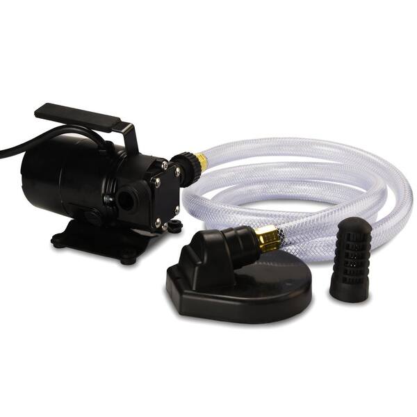
The "VIRAJ" make "VSPM" series is designed in self priming Non-clog Horizontal pump of Mono Block and only pump construction. This series pumps available with semi open type impeller s per customer application. This pump future is quick self priming action, long life due to replaceable wearing parts and for priming no need foot valve and easy maintenance and spare available.

The “pond” is actually a man made dam which covers an area of about 40ha and has rockfill embankments of up to 53m high along the southern side that forms the impoundment. It initially constructed in 1959 to act as a tailings pond to take the bauxite residue (red mud) from the Ewarton Plant situated about 5km away and 300m lower. The red mud was pumped as a slurry comprising about 20% solids to the pond over a period of about 32 years up to 1991 when the pond was replaced by the Charlemount Mud Stacking and Drying Facility. During this period the pond embankments (referred to as dams), were raised up to 7 times providing a final crest elevation of 472m. The pond was however never filled to its final design capacity and the mud beach level remained at about 469m and the central area about 458m leaving a concave depression which held about 1.4mil m3 of water with elevated pH and some caustic content.
The remediation plan for the pond includes the removal of the ponded water and then the regrading of the mud surface to be free draining so that it can be stabilised and vegetated. About 500,000 m3 of mud will need to be moved over a distance of up to 1km in order to create the required profile. Due to the very soft nature of the surface muds (shear strength of less than 3kPa) its bearing capacity is less than 20kPa hence it is not accessible using even modified earthworks equipment. In addition, the muds are thyrotrophic and under any vibration or shear loading, rapidly liquefy resulting in significant reduction in shear strength and loss of bearing capacity. Using conventional earthmoving equipment would therefore require extensive “floating” haul roads with a high risk of machinery getting stuck or entire plant loss and risk to personnel. It was therefore decided to investigate the possibility of pumping the in-situ red mud.
A mud pumping trial was undertaken to assess the feasibility of using this technique to do the bulk mud moving. Pumping red mud is not unusual and the muds were initially pumped up to Mt Rosser Pond. However, the muds are usually pumped at a solids content of 30% or less. Once deposited, they can take years to reconsolidate and firm up sufficiently to allow access for light earthworks and agricultural plant.
In addition to the mud pumping, the trial included infilling three small scale geotubes to assess their performance as these may be needed as part of the regrading works.
The main aim of the pump trial was to determine if the muds could be pumped in their insitu state, and if not, what amount of water is required and how the variations in water content affect pump rates.
The mud pumping trial was undertaken using a 4” EDDY Pump. This pump was recommended due to its ability to handle variable solids and robust operating mechanism. The pump unit incorporated a hydraulic drive and cutter head. The unit was mounted onto the boom of a JCB 220 excavator which also supplied the hydraulic feed to power the pump for the required range of 30-40 GPM at 3,500 to 4,000 psi (2428MPa). The cutter head was powered by a standalone hydraulic power unit capable of providing the required 30gpm at 200psi (1.9 l/s at 13.8MPa). If mounted on a 30-ton excavator with a System 14 hydraulic system and dual auxiliary feeds to the boom, all necessary hydraulic power for the pump and cutter head can be supplied by the excavator. This equipment was however not available at the time in Jamaica.
In addition to the pump mounted on the excavator a Long Reach excavator (CAT 325) was used to move muds towards the cutter head but also to loosen up the muds and mix in additional water to facilitate pumping. Water was added by pumping it directly from the pond using a 3” diesel water pump.
Prior to pumping the muds, the mud pump would operate in recirculation mode in order to prime the pump. When in recirculation (re-circ) mode, the material pumped would be diverted to a short discharge pipe mounted on the pump directed back parallel to the cutter head. This action would help agitate and stir the muds.
A geotechnical soils investigation was undertaken on the muds within Mt Rosser pond in 2004. It showed the material to be predominantly clayey silt with approximately 13% sand, 29% clay and 58% silt using conventional sieve analysis and hydrometer. Atterberg limits indicate that the material is an intermediate to high plasticity clay. The muds do however vary across the lake and also vertically. This is mainly as a consequence of the deposition process and discharge location. Close to the discharge location the courser materials would settle out first and the finer materials would disperse furthest and to the opposite end of the pond. The results are presented in figure 4.1.
Earlier this year, additional mud samples were tested as it was evident that standard soil mechanics tests did not provide an accurate assessment of this fine material. This was particularly evident in tests done with dry sieving which shows the material as well-graded sand (see results for samples 5300, 5301, 5302 on figure 4.2). When dispersed in water, even with an agent, the ‘yield-pseudo-plastic’ rheology of the muds appeared to affect the hydrometer results with large variations between tests (see results of samples PFT4&5 taken during mud pumping trials on figure 4.2).
The additional testing comprised of undertaking gradings using a Laser Particle Analyzer. The results indicated that the muds are predominantly Silt although the silt % varied from 30% to 80% with the material being either more sandy or more clayey (up to 15% clay). See results of samples ending in “L” on figure 4.2 below.
Moisture content tests on the muds taken from within the mud pond but below the ponded water ranged from 100% to 150% (50% to 40% solids). The muds at the pump test location were 137% (42% solids).
Shear strength was generally very low ranging from 1kPa to 6kPa increasing with depth. Dynamic probes previously undertaken indicated that the muds are “very soft” to 5m increasing in strength slightly to “soft” at a depth of 9m after which they increase to firm becoming stiff.
The pH of the muds ranged from 10.3 to 11.7, (ave 11.2). Previous testing indicated that the surface muds have the lower pH although once through the crust, the pH tends to be higher. When doing the trials, the muds up to a depth of about 2.5m was intermixed, hence any stratification in pH could not be determined.
Initially, pumping was problematic mainly due to the excavator being underpowered. This was diagnosed as a hydraulic pump problem and the excavator was replaced. The cutter head (which also acts to protect the intake) tended to blind with mud (Photo 5.1) and was also not providing enough agitation to liquefy the muds. This was partly resolved by adding “stirrers” (2 steel loops welded either side) to the rotating cutter head and also a “comb” (Photo 5.2) to keep the gaps within the cutter head open.
Mud pumping rates varied from 21 l/s to 52 l/s (332 – 824gpm) and it was clearly visible that the more liquid the muds were the higher the pump rate was. Samples were taken at different discharge rates and moisture content and percent solids determined by laboratory testing. The results are plotted in Figure 5.1 and although scattered, do give an indication of the effects of solids content on flow rates. The natural moisture content of the muds (insitu) at the test location was 137%, or 42% solids. This is shown in Figure 5.1 as a vertical line. Pumping muds close to the percent solids was achieved although flow rates were low.
As mentioned previously, the long reach excavator was used to loosen up the muds. Water was pumped from the pond using a 3” pump into the excavation and the long reach would then work the muds to mix the water in. The mud pump would then be used in recirculation mode to further mix the muds into a more consistent state. Even with this mixing and agitation, the water tended to concentrate on the surface. This aided the initial process of priming the pump and once primed thicker muds at 1m to 2m below the surface could be pumped. However, it was found that the deeper muds tended to be lumpy and this would significantly reduce or stop the flow requiring the pump to be lifted into thinner muds or having to go back into re-circ mode or having to fully re-prime. The pump discharge was therefore very inconsistent as the suction intake position constantly needed adjustment in an attempt to get adequate discharge but also pump the thickest muds possible.
Discharge of the pumped muds was through 30m of flexible hose then 60m of 4” HDPE pipe which had an internal diameter of about 87mm (3.5”). The muds were discharged onto the original mud beach which lies at a gradient of about 9%. On deposition the muds slowly flowed down gradient. At times the flow would stop and the muds would build up then flow again in a wave motion. The natural angle of repose would therefore be a few degrees less than this – probably 5% to 6%.
Although the muds have very low shear strength, and on agitation liquefy, the sides of the excavation had sufficient strength to stand about 2m near vertical. Even overnight, there was limited slumping and the bank could be undermined by about 0.5m with the cutter head/agitator before collapsing.
On termination of pumping, in order to flush the pipeline, thin watery muds were pumped until the line was clear. A “T” valve system was then used to connect the 3” water pump line and this was then used to flush the pipe with water.
Three geotubes (1m x 6m) were filled with red muds pumped using the 4” Eddy pump. Fill rates were about 30 to 40l/s although it was difficult to assess as the flow and mud consistence was not visible.
Tube 1 was filled initially with more runny mud and then thicker muds as the pump operator got a better feel for conditions. The tube was filled until firm. The second tube was filled with thicker muds and filling continued until the tube was taut. These two tubes were positioned on the sloping beach in order to form a small “U” impoundment area that would later be filled with pumped muds. Although the area was prepared, the sloping ground caused the first tube to rotate through about 20 degrees. The tube was staked and the downslope side backfilled. A more defined bed was created for the second tube and the same rotational issue was limited. The two filled tubes with the ponded mud are shown in Photos 5.7 and 5.8. Other than a small leak at the contact between the two geotubes, the ponding of the muds was successful.
The third tube was positioned on level ground. It was filled with medium runny (but consistent thickness) muds and was filled until the tube was taut.
In all three cases, there was very little mud loss or seepage from the tubes. When stood on, some red water would squeeze out around the pressure area. Once filled taut, the entire bag would have small red water droplets form on the outside (visible in Photo 5.11) , but the seepage was in general nominal.
The tubes have been monitored and the most recent photo’s taken on 10 October 2011 (6 weeks after filling) show how the tubes have reduced in volume due to the dewatering of the contained muds. Volume loss is estimated to be around 30%. The anticipated moisture content would therefore be about 90% and the solids around 53%.
The muds pumped into the trial pond behind the geotubes were medium thick to thick, probably in the order of 37 – 40% solids. After 6 weeks the mud has not only firmed-up but had dried out significantly with wide and deep surface cracks as are evident in Photo 5.14 and 5.15.
The muds can be pumped at close to their insitu moisture content and most likely at their in-situ moisture content if they were agitated more and the pipeline system was designed to reduce friction losses.
Be able to access the mud surface and move around efficiently and safely. The suggestion is to have the pump mounted on a pontoon that is positioned using high strength rope (dynema) or steel cable. The pump system should be remotely controlled as this would limit regular movement of personnel on the muds.
Have sufficient power and volume capacity to pump the muds at close to or at in-situ moisture content and discharge them about 1000m through a flexible pipeline.
It was also evident from the trials that the muds do not slump and flow readily. It will therefore be necessary to have an amphibious excavator to loosen up the muds in the area around the pump head. This weakened and more liquid mud would also aid the movement of the pump pontoon. To also limit the amount of movement the pontoon will need to do, the amphibious excavator could also move muds towards the pump location.
Using the capacity of the 4” mud pump, mud moving would take about 1.5 to 2 years, the pump will however need to be more suited to the task. A target period of 1 year however seems reasonable. However, prior to this, equipment will need to be procured and imported into Jamaica. The 6 and 10 inch Excavator Dredge Pump Attachments are also being considered as an option for higher GMP and a more aggressive completion timeline. A preliminary programme is as follows:

Mud-Pump Gear Sets . . . . . . . . . . . . . . . . . . . . . . . . . . . . . . . . . . . . . . . . . . . . . . . . . . . . . . . . . . . . . . . . . 13

A reciprocating power pump, as depicted in Figure 1, is a displacement machine. It has characteristics that are different than a centrifugal pump. Therefore, the system required for a displacement pump is different than that required for a centrifugal pump, and the operating procedures are also different. For instance, it is common practice to start a centrifugal pump against a closed discharge valve. Starting a displacement pump against a closed discharge valve can damage it. Preferably, a displacement pump should start against negligible discharge pressure. Starting a centrifugal against negligible pressure can damage it.
Therefore, to properly select, apply and operate a power pump requires knowledge of its unique characteristics. Some of these characteristics will be presented by stating common myths, misconceptions or misunderstandings and hopefully dispel some of them in the following list. Since some are not really full-blown myths, just misconceptions or misunderstandings, they will be called “MM.”
Power pumps are self priming.As was learned from operators of pressurized-water nuclear power plants, when a power pump ingests a slug of gas while running, one or more pumping chambers can become “vapor-locked” and cannot expel the gas and regain prime. It is necessary to reduce the pump discharge pressure to near (or below) suction pressure to allow the pump to reprime, and if the pump is running at a high speed with the necessary strong valve springs, priming may be more difficult.
If the first power pump chamber becomes primed, the remaining chambers will automatically become primed.If this were a multistage centrifugal pump, the statement would be true because all impellers are in series. However, in a multiplex power pump, the plungers (pumping chambers) are in parallel, so one chamber can become primed while the other chambers remain “vapor-locked.”
To prime a power pump, it is necessary to disassemble the liquid end.A project engineer once told me that, when starting a new processing plant containing new power pumps, to prime each pump, he would remove each discharge valve cover, remove each discharge valve, fill each pumping chamber with liquid and then reassemble the pump. He was pleased to learn that this laborious process was unnecessary. If the design of the system allows the operator to start the pump against negligible discharge pressure, most power pumps will prime all pumping chambers. Disassembly is not required.
If the pump is driven by a variable speed driver, a bypass line is not required.As discussed above, priming a power pump requires reducing the discharge pressure to near suction pressure, and this is typically accomplished by opening a valve in a bypass line, which connects back to the suction vessel. Such a line is illustrated in Figure 2. A variable speed driver does not eliminate the need for a bypass line.
The motor driver for a power pump needs to have a high starting torque.This misconception arises from the difficulty experienced when starting a power pump against a high discharge pressure. For many reasons, the pump should be started against negligible discharge pressure. The requirement for a high starting torque driver is thus eliminated.
A power pump can be run backward satisfactorily.Although the liquid end will pump the same regardless of the direction of the crankshaft rotation, running a power pump backward can result in a hot power end, power end knocking, reduced lubrication to the crossheads and bearings, and shorter packing life because of the resulting oscillations of the plungers.
Small, high-speed pumps produce lower pulsations than large, low-speed pumps.It has been stated that a smaller pump, running faster, for the same capacity, will produce less pulsation in the suction and discharge piping. That is not true because, as seen in Figure 3, the liquid velocity variation produced by a triplex pump, for example, is typically 25 percent of the average velocity, whether the pump is large or small, running fast or slow. The acceleration of the liquid in the piping, being the rate of change of velocity, is therefore larger for a small, high-speed pump than for a large, low-speed pump when both pumps have the same capacity and the same size piping.
All power pumps require pulsation dampeners.There are installations, with triplex and quintuplex pumps, that operate satisfactorily without pulsation dampeners. These installations are usually characterized by low-speed pumps and short, large-diameter suction and discharge piping.
A discharge pressure below the pump rated pressure indicates a problem with the pump.Unlike with a centrifugal pump, the discharge pressure of a displacement pump is established by the system. If there is low discharge pressure with a power pump, the cause is probably in the discharge system.
Power pumps can handle significant quantities of air or other gases.This one can really be trouble. Even small quantities of free gas flowing into a power pump will shorten the lives of numerous pump components. The higher the discharge pressure, the more damaging is the gas.
The check valves in power pumps are pushed closed by the reverse flow of the pumpage.It is the function of the valve spring to push the valve to near-closed as the plunger reaches the end of its stroke. Higher speeds require stronger springs. If the spring is not strong enough, the valve will be too far from the seat at the end of the stroke and will be slammed onto the seat by the reverse flow of the pumpage. Such action results in a noisy, rough-running pump and shaking pipes.
All power pumps require at least 10 psi of NPSH.Power pumps, when operated near their top rated speeds, require strong valve springs to obtain smooth operation. It is typical for such pumps to require 10 psi, or more, of net positive suction head (NPSH). However, if the pump speed is reduced to a value below about 200 rpm, the springs on vertical suction valves can be removed, and the net positive suction head required (NPSHR) will drop to about 1 psi (less than many centrifugal pumps).
A high suction pressure requires strong suction valve springs.This initially sounds reasonable, but further examination reveals otherwise. A check valve in a power pump is pushed open by the differential pressure of the pumpage. A suction valve is therefore opened by the difference between the suction pressure and the pressure in the pumping chamber. As the plunger pulls back on the suction stroke, the pressure in the chamber falls. When the pressure falls to a value that is just below suction pressure, the suction valve begins to open. The valve knows not the difference between suction pressure and atmospheric pressure. It knows only the difference between suction pressure and chamber pressure. This principle is illustrated by a low-speed pump, pumping propane, which is provided with an inlet pressure of 150 psia. To minimize NPSHR, the springs are removed from the suction valves. Pump operation is quiet and smooth, and the pump achieves high volumetric efficiency. The pump has a high suction pressure and operates satisfactorily with no springs on the suction valves.
Because the top of the pump valve is larger than the “exposed” bottom of the valve, a significant differential pressure is required to open the valve.Figure 4, taken from an article on power pumps, illustrates this theory. The article stated that a high differential pressure was required to kick the valve open. It may be true that a valve with an elastomeric or soft plastic sealing element exhibits such a characteristic, but an all-metal valve does not require a high differential pressure to kick it open. If it did, we could not have pumps that operate satisfactorily with one psi of net positive suction head available (NPSHA).
The allowable lift of a power pump valve is proportional to its diameter.This concept seems to have originated with Reference 1 and was perpetuated by Reference 2. As revealed in Reference 8, the maximum allowable valve lift for smooth pump operation appears to be solely a function of the rpm of the pump crankshaft. It is independent of valve size.
All power pumps are suitable for slurry service.Don’t believe it. Most power pumps are designed to pump only clean (non-abrasive) fluids. Slurry applications require special valves and stuffing box designs. An entire special fluid end may be required.
If the packing on one plunger fails, the packing on the other plungers is near failure.This is often not true. For multiple reasons, one set of packing in a pump can fail prematurely. The other sets of packing may last weeks or months longer. Because of possible improper installation or startup procedure of replacement packing, changing good packing can actually result in a shorter life. Changing all packing, when one set fails, can also mask a problem with one particular stuffing box—such as misalignment or a scored plunger. If it ain’t broke, don’t fix it.
Wright, Elliott F., “New Developments in Reciprocating Power Pumps,” a paper presented to the 6th meeting of the National Conference on Industrial Hydraulics, 1955.
Henshaw, Terry, “Power Pump Valve Dynamics – A Study of the Velocity and Pressure Distribution in Outward-Flow Bevel-Face and Flat-Face Power Pump Valves,” a technical paper presented at the 25th International Pump Users Symposium, Houston, Texas, 2009.
Henshaw, T., “Think power pumps are self-priming? Think again!” Hydrocarbon Processing Magazine, December 2009. 10. Henshaw, Terry, “Improve Power Pump Performance with Stronger Valve Springs”, Compressor Tech Two, July 2010.

Moonlighting 1. No employee covered by this Agreement shall hold an active C17 or work on his/her own behalf as a self-employed individual after his regular hours of employment, or on Saturdays, Sundays, Holidays and designated days off on any work covered by the jurisdiction of this Agreement.
The 2,200-hp mud pump for offshore applications is a single-acting reciprocating triplex mud pump designed for high fluid flow rates, even at low operating speeds, and with a long stroke design. These features reduce the number of load reversals in critical components and increase the life of fluid end parts.
The pump’s critical components are strategically placed to make maintenance and inspection far easier and safer. The two-piece, quick-release piston rod lets you remove the piston without disturbing the liner, minimizing downtime when you’re replacing fluid parts.

My first days as an MWD field tech I heard horror stories surrounding what is commonly referred to as “pump noise”. I quickly identified the importance of learning to properly identify this “noise”. From the way it was explained to me, this skill might prevent the company you work from losing a job with an exploration company, satisfy your supervisor or even allow you to become regarded as hero within your organization if you’ve proven yourself handy at this skill.
“Pump noise” is a reference to an instability in surface pressure created by the mud pumps on a modern drilling rig, often conflated with any pressure fluctuation at a similar frequency to pulses generated by a mud pulser, but caused by a source external to the mud pulser. This change in pressure is what stands in the way of the decoder properly understanding what the MWD tool is trying to communicate. For the better part of the first year of learning my role I wrongly assumed that all “noise” would be something audible to the human ear, but this is rarely the case.
A mud pulser is a valve that briefly inhibits flow of drilling fluid traveling through the drill string, creating a sharp rise and fall of pressure seen on surface, also known as a “pulse”.
Depending on if the drilling fluid is being circulated in closed or open loop, it will be drawn from a tank or a plastic lined reservoir by a series(or one) mud pumps and channeled into the stand pipe, which runs up the derrick to the Kelly-hose, through the saver sub and down the drill-pipe(drill-string). Through the filter screen past an agitator or exciter, around the MWD tool, through a mud motor and out of the nozzles in the bit. At this point the fluid begins it’s journey back to the drilling rig through the annulus, past the BOP then out of the flow line and either over the shale shakers and/or back in the fluid reservoir.
Developing a firm grasp on these fundamentals were instrumental in my success as a field technician and an effective troubleshooter. As you can tell, there are a lot of components involved in this conduit which a mud pulser telemeters through. The way in which many of these components interact with the drilling fluid can suddenly change in ways that slightly create sharp changes in pressure, often referred to as “noise”. This “noise” creates difficulty for the decoder by suddenly reducing or increasing pressure in a manner that the decoder interprets a pulse. To isolate these issues, you must first acknowledge potential of their existence. I will give few examples of some of these instances below:
Suction screens on intake hoses will occasionally be too large, fail or become unfastened thus allowing large debris in the mud system. Depending on the size of debris and a little bit of luck it can end up in an area that will inhibit flow, circumstantially resulting in a sudden fluctuation of pressure.
Any solid form of drilling fluid additive, if improperly or inconsistently mixed, can restrict the flow path of the fluid resulting in pressure increase. Most notably this can happen at the pulser valve itself, but it is not the only possible outcome. Several other parts of this system can be affected as well. LCM or loss of circulation material is by far the most common additive, but the least overlooked. It’s important for an MWD technician to be aware of what’s being added into the drilling fluid regardless if LCM isn’t present. Through the years I have seen serval other improperly mixed additives cause a litany of pressure related issues.
This specifically is a term used to refer to the mud motor stator rubber deterioration, tearing into small pieces and passing through the nozzles of the bit. Brief spikes in pressure as chunks of rubber pass through one or more nozzles of the bit can often be wrongly interpreted as pulses.
Sometimes when mud is displaced or a pump suction isn’t completely submerged, tiny air bubbles are introduced into the drilling fluid. Being that air compresses and fluid does not, pulses can be significantly diminished and sometimes non-existent.
As many of you know the downhole mud motor is what enables most drilling rigs to steer a well to a targeted location. The motor generates bit RPM by converting fluid velocity to rotor/bit RPM, otherwise known as hydraulic horsepower. Anything downhole that interacts with the bit will inevitably affect surface pressure. One of the most common is bit weight. As bit weight is increased, so does surface pressure. It’s important to note that consistent weight tends to be helpful to the decoder by increasing the amplitude of pulses, but inconsistent bit weight, depending on frequency of change, can negatively affect decoding. Bit bounce, bit bite and inconsistent weight transfer can all cause pressure oscillation resulting in poor decoding. Improper bit speed or bit type relative to a given formation are other examples of possible culprits as well.
Over time mud pump components wear to the point failure. Pump pistons(swabs), liners, valves and valve seats are all necessary components for generating stable pressure. These are the moving parts on the fluid side of the pump and the most frequent point of failure. Another possible culprit but less common is an inadequately charged pulsation dampener. Deteriorating rubber hoses anywhere in the fluid path, from the mud pump to the saver sub, such as a kelly-hose, can cause an occasional pressure oscillation.
If I could change one thing about today’s directional drilling industry, it would be eliminating the term “pump noise”. The misleading term alone has caused confusion for countless people working on a drilling rig. On the other hand, I’m happy to have learned these lessons the hard way because they seem engrained into my memory. As technology improves, so does the opportunities for MWD technology companies to provide useful solutions. Solutions to aid MWD service providers to properly isolate or overcome the challenges that lead to decoding issues. As an industry we have come a lot further from when I had started, but there is much left to be desired. I’m happy I can use my experiences by contributing to an organization capable of acknowledging and overcoming these obstacles through the development of new technology.

This invention relates to apparatus useful in connection with the drilling of wells, such as oil wells, wherein a mud pump is used to circulate drilling mud under pressure through a drill string, down to and around the drill bit and out the annulus of the bore hole of the well to a mud reservoir; the apparatus of the present invention being useful for simultaneously degassing drilling mud and supercharging the mud pump.
In the drilling of deep wells, such as oil wells, it is common practice to penetrate the earth with a drill bit supported on a drill string in the bore of the well being drilled. In order to lubricate the drill bit, protect the well against blowouts, etc., it is conventional practice to circulate mud under pressure through the drill string down to and around the drill bit and up the annulus between the drill string and the bore of the well. Mud flowing from the well is passed through a suitable device such as a shaker, etc., in order to remove drill cuttings, etc., and is then delivered to a mud reservoir, such as a mud tank, for recirculation to the mud pump for pressured injection into the well.
It is also conventional practice to use a mud pump, such as a duplex or triplex mud pump comprising reciprocating pistons mounted in cylinders for pressuring the incoming drilling mud and delivering it to the well bore under pressure. The operation and construction of mud pumps is well known to those of ordinary skill in the art, as illustrated, for example, by the textbook "Mud Pump Handbook" by Samuel L. Collier (Gulf Publishing Company, Houston, Tex., 1983).
It is known, as explained in the Collier handbook, that the efficiency of a mud pump can be significantly improved by supercharging the pump; that is, by delivering drilling mud under pressure to the mud pump inlet to the cylinders containing the reciprocating pumping pistons.
It is also known to remove occluded gasses such as air, methane, etc., from drilling mud before it is delivered to the mud pump as illustrated, for example, by Burgess U.S. Pat. No. 3,973,930, Burgess U.S. Pat. No. 3,999,965 and Burgess U.S. Pat. No. 4,084,946.
Other drilling mud degassing devices are known to the art, such as those disclosed in Phillips et al. U.S. Pat. No. 4,088,457, Brown et al. U.S. Pat. No. 4,113,452, Egbert U.S. Pat. No. 4,365,977, Gowan et al. U.S. Pat. No. 4,397,659, etc.
Mud pumps used for delivering drilling mud under pressure to the bore hole of a well are conventionally of the type wherein a reciprocating piston in a cylinder is used to pressure drilling mud delivered to the cylinder for delivery to the well bore. Normally, two or three such cylinders are used, such pumps being conventionally referred to as duplex and triplex pumps. During each stroke of the piston, the piston is initially accelerated by an appropriate drive means, such as a crank shaft, from a starting position to a midcylinder position, and then decelerated to a final position within the cylinder. This constantly changing rate of motion of a reciprocating piston can result in knocking, cavitation, etc., all of which impair the efficiency of the pump. It is known to use centrifugal pumps, commonly known as superchargers, in order to deliver drilling mud to the inlet of the cylinder under pressure in order to alleviate such problems and improve the efficiency of operation of the pump.
It is undesirable to recirculate drilling mud containing occluded gases to a well bore, and therefore it is common practice to remove a significant portion of occluded gas from the drilling mud before it is recirculated to the mud pump. Normally, separate pieces of equipment that operate independently of each other are used for supercharging the mud pump and for degassing the drilling mud.
It has been discovered in accordance with the present invention that a drilling mud degasser of the type disclosed in the Burgess patents can be modified to simultaneously degas drilling mud and to supercharge the mud pump to which the degassed mud is to be delivered.
This is accomplished in accordance with the present invention through the provision of a device for simultaneously supercharging a mud pump having pistons reciprocably mounted in cylinders while degassing drilling mud to be delivered to said pistons comprising:
vacuum chamber means for continuously accelerating and centrifuging drilling mud under vacuum to thereby substantially completely remove occluded gas from the drilling mud,
a first conduit interconnecting said vacuum chamber with a drilling mud reservoir for delivering drilling mud to be degassed to said vacuum chamber means,
a first valve controlled branch conduit interconnecting said second conduit with said drilling mud reservoir for delivering drilling mud to said drilling mud reservoir when the pressure in said second conduit exceeds a predetermined value, and
a second branch conduit containing normally closed flow control means interconnecting said second conduit with said first conduit and said drilling mud reservoir operable on loss of pressure in said second conduit to permit flow of drilling mud directly from said drilling mud reservoir to said second conduit.
Referring now to the drawing, there is shown a supercharging drilling mud degasser 10 of the present invention which comprises a degassing chamber designated generally by the number 12, a power source such as an electric powered motor or a hydraulically powered motor designated generally by the number 14, a vacuum blower such as a regenerative vacuum blower, designated generally by the number 16, a gear box designated generally by the number 18, an evacuation pump designated generally by the number 20 and a drilling mud chamber designated generally by the number 22.
In accordance with this construction, there is provided a drilling mud degasser of the type shown in Burgess U.S. Pat. No. 4,084,946, housed in a cylindrical pressure vessel 24. The motor 14 is supported on vacuum blower 16 which, in turn, is supported by vacuum motor support 26 and vacuum blower brackets 28. To facilitate movement of the degasser 10, motor handling brackets 30 may be provided on the top of the motor 14 to which the hook of a crane or other appropriate means (not shown) may be attached.
Drilling mud pump impeller 42 is fixed to the centrifuge tube 40 for rotation therewith within the housing 46 of drilling mud evacuation pump 20. Cross braces 48 mounted in the cylindrical vessel 24 support lower stops 50 and upper stops 52 for an annular float 56 that surrounds the slots of the centrifuge tube 40 and partially closes them, such that the free area of the slots will be determined by the relative position of the annular float 56.
A drilling mud inlet 60 is connected to the bottom of the housing 46 for the evacuation pump 20 for the delivery of degassed drilling mud thereto. Drilling mud is delivered to the slotted centrifuge tube 40 by an inlet conduit 62 which preferably terminates inside the housing 46 for the evacuation pump 20. The top of the inlet line 62 is spaced from the bottom of the slotted centrifuge tube 40 so that the rotating centrifuge tube 40 can rotate freely without bearing upon the top of the inlet line 62. The resultant "controlled seepage" of fluid from the inlet tube 62 into the evacuation pump 20 provides a low pressure area for high effeciency scanvenging of occluded gases. Also, there is no need for bearings and seals at the bottom of the slotted centrifuge tube 40.
With this construction there is also provided an outlet line or conduit 66 connected with the discharge side of the evacuation pump 20 and extending through the wall of the cylinder 24 for connection with a suitable first conduit 68 leading, for example, to a triplex pump 70 for injecting drilling mud under pressure into a well penetrating a subterranean formation in order to lubricate the drill bit, protect the well against blow outs, etc., it is conventional practice to circulate mud under pressure through the drill string down to and around the drill bit and up the annulus beteen the drill string and the bore of the well. Mud flowing from the well is passed through a suitable device such as a shaker, etc. (not shown) in order to remove drill cuttings, etc., and is then delivered to a mud reservoir, such as a mud tank 84, for recirculation to the mud pump 70 in the manner described herein for pressured injection into the well.
The first conduit 68 may comprise, for example, a connecting pipe 72 interconnecting the outlet line 66 with the flexible hose 74 which, in turn, is connected to a mud pump inlet line 76. The flexible hose 74, which is provided for ease in alignment, may be secured to the connecting pipe 72 by a clamp 78 of any suitable construction and to the mud pump inlet line 76 by a clamp 80 of any suitable construction.
A second conduit 82 interconnects a drilling mud reservoir such as a mud tank 84 with the inlet conduit 62 leading to the slotted centrifuge tube 40 for the degasser 10.
Preferably, the second conduit 82 is provided with valve means such as a butterfly valve 86 which may be used to close the second conduit 82 when both the drilling mud degasser 10 and the mud pump 70 are to be idled for any appreciable time.
A first branch conduit 88 interconnects the first conduit 68 with the mud tank 84 and contains pressure sensitive control means such as a spring biased relief valve 90 in order to permit drilling mud to recycle from the first conduit 68 to the mud tank 84 when the pressure in the first conduit 68 exceeds a predetermined value.
A second branch conduit 92 interconnects the first conduit 68 with the inlet conduit 62 and the second conduit 82. The second branch conduit 92 contains normally closed flow control means such as a check valve 94 to permit flow of drilling mud directly from the mud tank 84 to the mud pump 70 if the pressure in the first conduit 68 falls below a predetermined value.
During drilling operations, rotation of an appropriate vacuum blower such as a regenerative vacuum blower by the drive shaft 32 for the motor 14 will generate a vacuum in the degassing chamber 12 such that drilling mud sprayed from the slots in the centrifuge tube 40 will tend to impact upon the inner sides of the degassing chamber 12 thereby initiating degassing of the drilling mud fed through the inlet line 62. Rotation of the centrifuge tube 40 will impart upward accelerating rotary motion to partially degassed drilling mud delivered thereto through the line 62 and the resultant spraying of the thus centrifuged drilling mud through the slots in the centrifuge tube 40 will result in a sheet of drilling mud being sprayed onto and impacting on the inner walls of the degassing chamber 12 to thus substantially complete the removal of gas from the drilling mud. The thus degassed drilling mud will flow downwardly past cross braces 48 and into inlet 60 leading through the housing 46 of the evacuation pump 20 where the impeller 42 will repressure the now degassed drilling mud for discharge through the outlet line 66 which is interconnected with a triplex pump 70 by first conduit 68 for supercharging the pump 70, which further pressures the degassed drilling mud for injection into a well bore penetrating a subterranean formation.
In order to prevent the entrainment of drilling mud droplets in the gases withdrawn through the gas evacuation suction pipe 98, a splatter plate 100 is provided in the degassing chamber 12 and a combination of a foam separation impeller 36 with a splatter disk 102 is provided adjacent the top of the degassing chamber 12 so that gas liberated in the vacuum chamber must follow a sinuous path arriving at the upper chamber gas evacuation suction pipe 98.
In accordance with the present invention, the motor 14 is operated such that drilling mud delivered to the first conduit 68 will be at a predetermined appropriate supercharging pressure for the mud pump 70, (e.g. a pressure of about 20 to 30 psig).
The pressure sensitive control means, such as a spring biased relief valve 90, is set to open at a predetermined pressure about 5 to 10 psi higher than the desired pressure in the first conduit 68 so that, if the indicated pressure limit is exceeded, the pressure relief valve 90 will open in order to permit drilling mud to recycle to the mud tank 84.
This will happen if the mud pump 70 malfunctions and also when the mud pump 70 is turned off, as will happen from time to time. For example, it is necessary to turn off the mud pump 70 during drilling operations when a new stand of drill pipe is to be added to the drill string. It is also necessary to turn off the mud pump 70 when the drill string is being withdrawn from the well bore in order to replace the drill bit, while well logging operations are in progress, if it is necessary to "fish" for a piece of equipment lost down the hole, etc. However, if the drilling mud in the mud tank 84 is permitted to remain quiescent for more than a limited period of time, the drilling mud may start to gel and/or to stratify. This problem is conventionally avoided by providing a separate agitator (not shown) for the mud tank 84 in order to stir the drilling mud when the mud pump 70 is idle. However, through the provision of the present invention, there is no need for a separate agitator for the mud tank 84 because recirculation of drilling mud through the first branch conduit 88 will impart a "roiling" motion or agitation to the drilling mud in mud tank 84 to inhibit gelling and/or stratification of the drilling mud while the mud pump 70 is idle.
Loss of pressure in the first conduit 68 can occur in the event of malfunction of the degasser 10 or in the event it is desired to shut the degasser 10 down for a limited period of time. In this event, drilling mud flows directly from the mud tank 84 through the second conduit 82, the second branch conduit 92 and the flexible hose 74 to the mud pump 70 so that the mud pum 70 is not "starved" for drilling mud to be injected into the well.

A ship consists of various types of fluids moving inside different machinery and systems for the purpose of cooling, heating, lubrication, and as fuels. These liquids are circulated by different types of pumps, which can be independently driven by ship power supply or attached to the machinery itself. All the systems on board ship require proper operational and compatible pump and pumping system so that ship can run on its voyage smoothly.
The selection of a type of pump for a system depends on the characteristics of the fluid to be pumped or circulated. Characteristics such as viscosity, density, surface tension and compressibility, along with characteristics of the system such as require rate of fluid, head to which the fluid is to be pumped, temperature encountered in the system, and pressure tackled by the fluid in the system, are taken into account.

Discharge Head: This is the vertical distance that you are able to pump liquid. For example, if your pump is rated for a maximum head of 18 feet, this does not mean that you are restricted to 18 feet of pipe. You can use 300 feet, so long as the final discharge point is not higher than 18 feet above the liquid being pumped.
Suction Lift: This is the vertical distance that the pump can be above the liquid source. Typically, atmospheric pressure limits vertical suction lift of pumps to 25 feet at sea level. This does not mean that you are limited to 25 feet of pipe. You could use upwards of 300 feet of suction pipe, so long as the liquid source is not lower than 25 feet below the pump center line.

DAE Pumps dredging equipment is ideal for a variety of applications, including dredging dams, ports, marinas, rivers, canals, lakes, ponds, and more. Ensuring water quality and capacity are essential in hydroelectric and water supply dams, making DAE Pumps dredge pumps perfect for removing excess sand and silt. Clearing sediment and contaminates from riverbeds, channels, canals, and oceans help restore safe navigation and shoreline formations, and dredging lakes and ponds clean and remove contaminants and tailing. As ocean currents move sediments, the seafloor slowly rises, lowering the depth of marinas and ports. Dredging ensures safe access for boats and other water vessels.
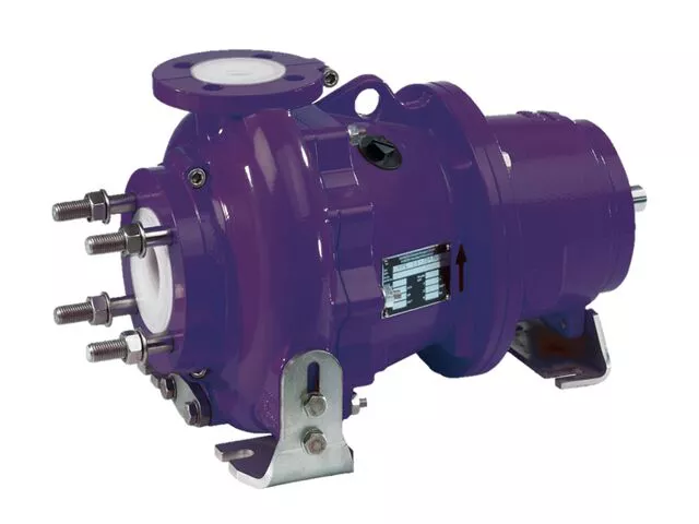
Centrifugal pumps from DAE Pumps are perfectly suited for demanding process applications. Their heavy-duty construction ensures long-lasting performance in rugged conditions. The DAE Pumps knowledge and experience building top-of-the-line pumps make our centrifugal process pumps ideal in many markets and applications.
The durable DAE Pumps centrifugal pumps provide a proven ability to handle a variety of applications in the water and wastewater industries. These reliable instruments are perfect solutions for pumping chemicals used to treat water, irrigation, fountains, and much more.
For help selecting the most efficient pump for your project, call us at (760) 821-8112 or submit a request. Find the right pump size, volume, speed that you need. Get a FREE custom pump curve to ensure the right pump.
The motor or engine on a pump is as important as the pump itself. It is the driving force that makes the pump go. DAE Pumps offer a variety of motor choices: electric, diesel, and hydraulic.
Our close-coupled electric motors reduce the stress on motor bearings with a short shaft overhang and fan-cooled. Our submersible electric motors come completely enclosed with the most trusted watertight O-ring seals. Diesel engines offer self-priming features and easy to maintain capabilities. Hydraulic motors are powered by HPU or hydraulic power units and provide the utmost in capability and performance.
Frames and skids hold the pump and motor together to make a complete unit. The frame provides stability for the placement of the pump and motor with the intent of a permanent install or seldom movement. The DAE Pumps trailer brings mobility to centrifugal slurry pumps. The whole unit, skid included, is mounted onto a trailer for mobile accessibility. Many industries use centrifugal pumps for performing multiple applications, and they move from one location to another quite frequently. The trailer provides a tremendous advantage of being on wheels.
Centrifugal pumps come in many shapes and sizes. There are two main parts to a centrifugal pump; the pump and the motor/engine. The electric motor or a diesel engine converts the energy it creates into mechanical energy. This mechanical energy drives the pump and moves the water. The centrifugal slurry pumps pull water and other materials in through the inlet and pushes it out through the outlet/discharge.
The electric motor and diesel engine work relatively similarly. A motor consists of a fan and protective casing mounted at the back. Inside the motor is the stator. The stator holds copper coils. Concentric to this is the rotor and shaft. The rotor rotates, and as it spins, so does the pump shaft. The shaft runs the entire length of the motor and into the pump where it connects to the pump’s impeller.
There are a couple of variations to a centrifugal pump. Some models of centrifugal pumps have a separate shaft for the pump and the motor. The connection between the separated shafts is called the coupling. These coupled pumps will contain a bearing house with bearings. The pump shaft then continues into the pump casing. As it enters the casing it passes through a gland, packing, and the stuffing box, which combined to form a seal. The shaft then connects to the impeller. The impeller imparts centrifugal force onto the fluid that makes it to move liquids through a pipe or hose. The impeller is in the pump casing. The casing contains and directs the flow of water as the impeller pulls it in through the suction inlet and pushes it out through the discharge outlet.
At the back of the motor, the fan connects to the shaft. The motor rotates the shaft and fan. The fan cools down the motor/engine, and it blows ambient air over the casing to dissipate unwanted heat. If the motor becomes too hot, the insulation on the coils inside the motor melts, causing the motor or engine to short circuit and destroy itself. The fins on the outside perimeter of the casing increase the surface area of the casing, which allows for removing more unwanted heat. The motor comes in either three-phase or single-phase configuration, depending on the application.
At the pump casing, there is a channel for water to flow along, which is called the volute. The volute spirals around the perimeter of the pump casing to the outlet. This channel increases in diameter as it makes its way to the outlet. The shaft passes through the seals and into the pump casing, where it connects to the impeller.
Liquid engulfs the impeller, and when it rotates, the fluid within the impeller also spins and is forced outward to the volute. As the fluid moves outwards, off of the impeller, it creates a region of low pressure that pulls more water in through the suction inlet. The fluids enter the eye of the impeller and are trapped there between the blades. As the impeller rotates, it imparts kinetic energy or velocity onto the liquid. By the time the liquid reaches the edge of the impeller, it is moving at a very high speed. This high-speed liquid flows into the volute where it hits the wall of a pump casing. This impact converts the velocity into potential energy or pressure. More fluid follows behind this developing a flow.
The thickness of the impeller and the rotational speed affects the volume flow rate of the pump and the diameter of the impeller, and the rotational speed increases the pressure it can produce.
Net Positive Suction Pressure or NPSH is associated with pump suction. At the end of this acronym are two other letters NPSHR and NPSHA. The R is the required NPSH. Each pump tests for this value. At DAE Pumps, we provide a pump operation chart with all our specs. The R-value is a warning or danger point. As the fluid enters the pump and flows into the impeller’s eye, it experiences a lot of energy due to the friction, giving a pressure drop. At certain conditions, the fluids flowing through this section can reach a boiling point. Once this happens, cavitation may occur.
The last letter in NPSHA stands for Available. The net positive suction pressure available depends on the installation of the pump and should be calculated. NPSHA takes into consideration things like insulation types, elevation, liquid temperature, liquid boiling point, much more. Available pressure should always be higher than the required value. For example, if the NPSHA is 12 for the pump requiring an NPSHR of 4 then the pump should be okay. However, a pump that required an NPSHR of 15 than the available NPSH is insufficient, and cavitation will occur.
DAE Pumps provides custom pump curves per the information you provide. Including as much information about the project allow us to best match a pump with your needs, so the centrifugal pump you get is ideal for the project.
Cavitation in pumps is the deterioration of the pump’s metal due to the overheating of water. Cavitation destroys the pump’s impeller and casing that lead to replacing parts and the pump altogether.
Water can turn from a liquid state into steam or gas and boils at around 100 degrees Celsius at sea level. However, at a higher elevation, water boils at a lower temperature because of atmospheric pressure. If this pressure is less than the vapor pressure of the liquid that is pumping, then the water can reach a boiling point. When this happens, cavitation occurs.
During cavitation, air particles within the water expand, and as they reach the boiling point, they collapse in on themselves very rapidly. As they collapse, they start to damage the impeller and pump casing. This damage removes small parts of metal from the surface, and if this keeps occurring, then it will eventually destroy the pump. Therefore, you must ensure the Available pressure is higher than the Required pressure of the pump.
DAE Pumps provides a full spectrum of centrifugal slurry pumps and accessories for completing all your tough dredging projects.We provide turnkey solutions with complete centrifugal slurry pump systems that includeslurry hoses, slurry flow meters, power units,and more.Choose from multiple sizes of slurry hoses for the transferring of materials, wireless flow meters for measuring the flow rate in gallons per minute of liquid, and power units for operation.Parts are always in stock and available for immediate shipping to anywhere in the US and the world.
This website is using a security service to protect itself from online attacks. The action you just performed triggered the security solution. There are several actions that could trigger this block including submitting a certain word or phrase, a SQL command or malformed data.


 8613371530291