
steam engine made from mud pump liners manufacturer
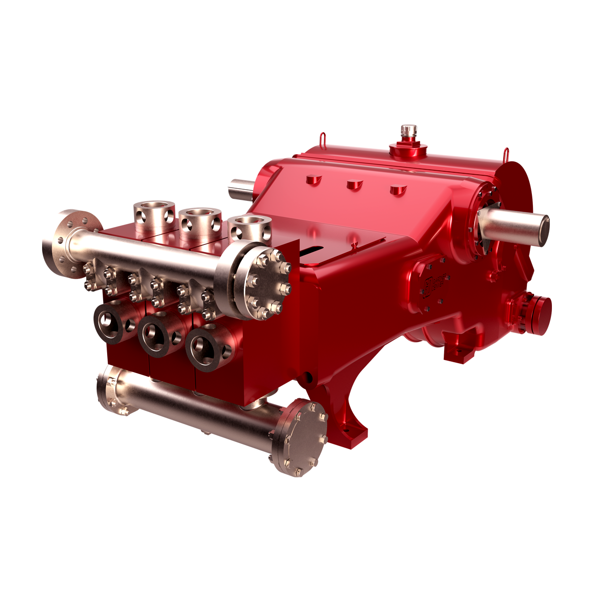
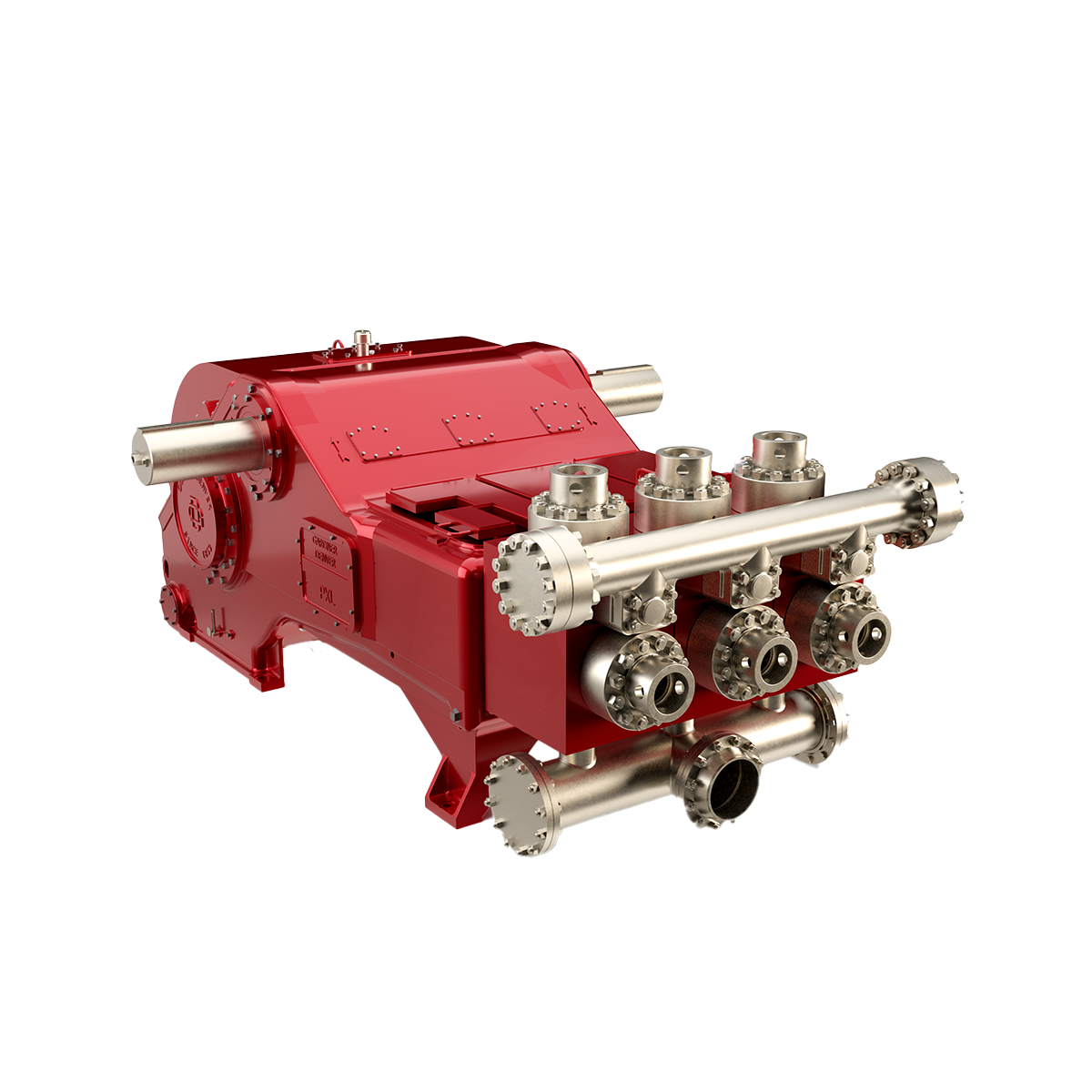
GDEP is the original creator of the drilling pump and continues to set the standard for durable, high-quality drilling pumps that can withstand the world’s toughest drilling environments. Starting with our PZ7 and rounding out with the market"s most popular pump, the PZ1600, our PZ Series of pumps are the perfect choice for today"s high-pressure drilling applications.
With strong manufacturing and machining capacities, main parts and key components of our products are made by CNC machines. More than 400 types of advanced equipment with high accuracy, strong reliability and advanced machining processes are available with QNP, such as the Mitsubishi Planer five sides machining center, the Italy horizontal slotting machine, the 10 meters CNC heavy duty horizontal lathe, the 8 meters vertical lathe, the 6 meters CNC grinding machine, the CNC gantry milling and drilling machine, the CNC gantry wrapping machine and the winding machine for generators. The components are standardized and modularized with enhanced universality and compatibility.
The rapid development of QNP has captured the attention of the Fortune Global 500 companies, such as the M AN Group from Germany, and Mitsubishi Heavy Industries from Japan. These companies and numerous others have worked with QNP for technical exchanges.
QNP has also gotten strong support from central and local government. Top government officials at all levels have visited QNP many times and given high ratings on QNP`s development.
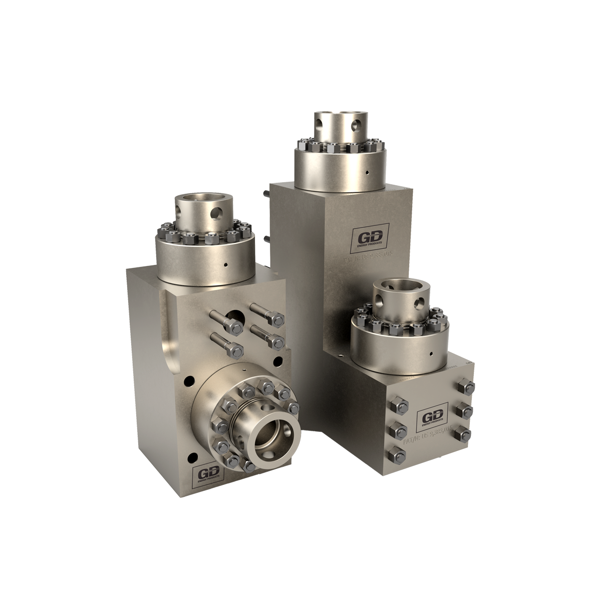
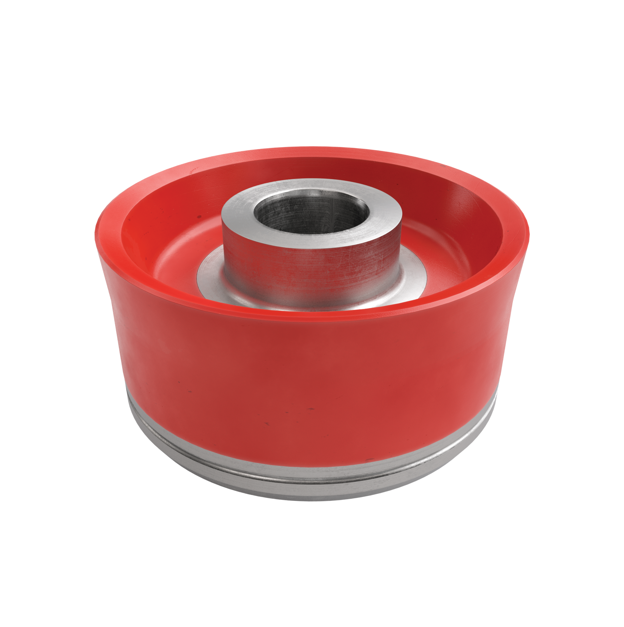
Lake Petro provides high quality Mud Pump Parts including Mud Pump Liners, Mud Pump Fluid End Module, piston, Valve and Seat etc. With more than 10 years of experience in the oil and gas industry, we are dedicated to help and support our loyal clients with the most cost-effective and quality Liners and Pistons. We also provide mud pump price and mud pump for sale.
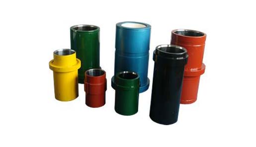
We offer Liners with Ceramic (Zirconia and Aluminium oxide) and Steel (Metal and Bi-metal) materials for all common brands of the mud pump and triplex mud pump.
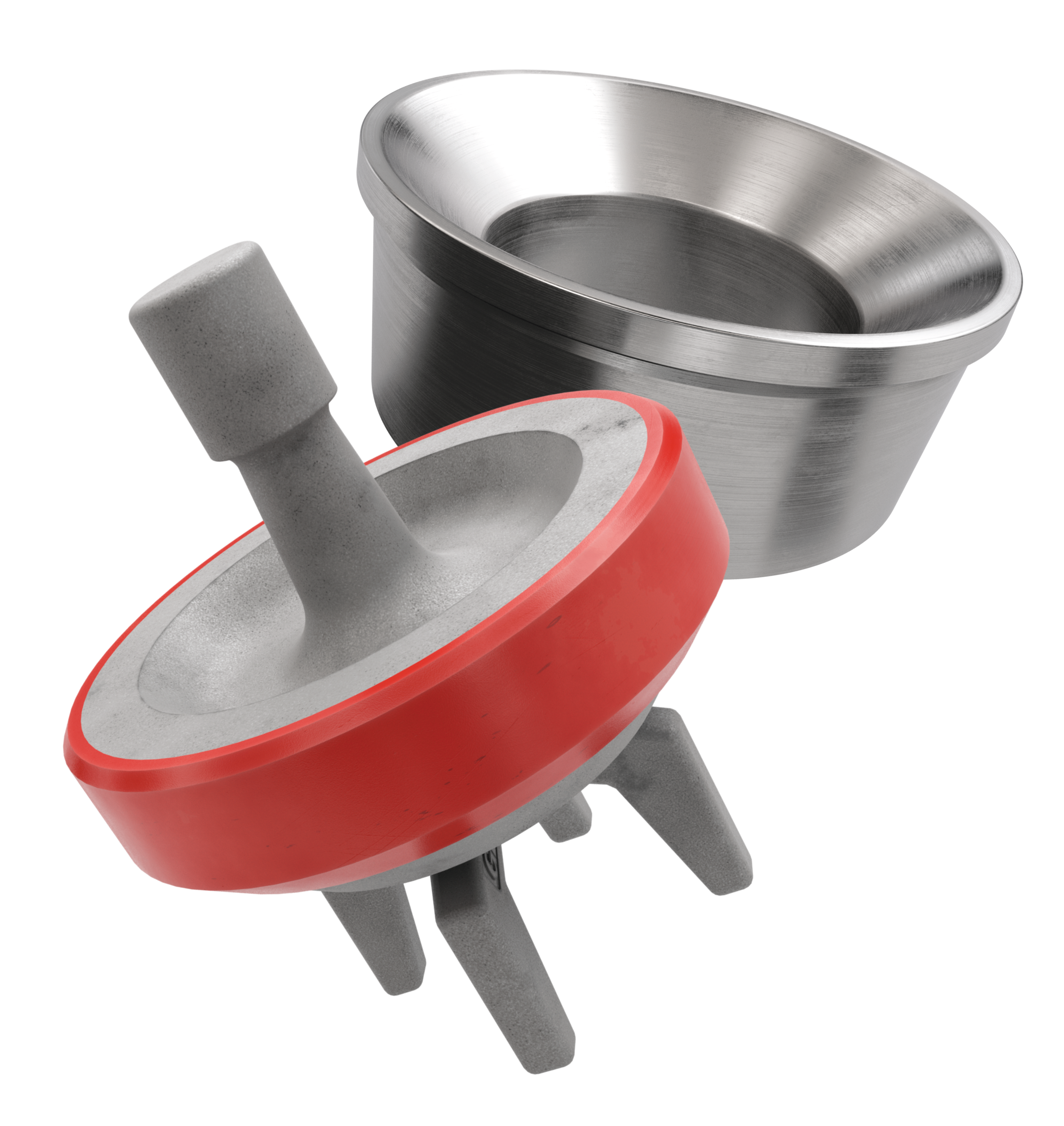
Bi-metal liners (double metal liners) are made of forged steel shell and wear-resistant sleeve of high chromium iron. In the production process, the size accuracy should be strictly controlled, which can ensure that they can be easily and stably installed. The inner sleeve with high finish and hardness is wear-resistant, corrosion-resistant and has a long service life. The bi-metal liners are suitable for a lot of bad working conditions. Its service life is more than 800 hours.
Ceramic Liners are made of a ceramic inner sleeve and a forged steel outer shell. The service life of ceramic liners is about 4000 to 10000 hours, the minimum time is at least 2000 hours, which is a lot more than bi-metal liners. Because of the phase transformation toughen technology, the ceramic liners have the features of wear-resistance, erosion-resistance, high-pressure-resistance, high hardness and strength. Zirconia type and Alumina type are common type of ceramic sleeve. Compared with Alumina type, Zirconia type liners have better toughness properties and a much longer service life. Piston wear and water consumption for lubrication can be reduced as well.
Seal Rings for Liner packing are also important. Liner Seal Rings is designed and made with hard corner which is an integral part of seal rings and soft nitrile element rubber center. We could provide reliable liner Seal Rings for our customers could order them at the same time.
All Lake Petro liner products are interchangeable with O.E.M. products. Meanwhile, we provide customized Liners according to drawings. Our liners, also with our other mud pump spares, are supplied for use in Honghua, F-Series, Bomco, Emsco and National lines of triplex drilling pumps. Let Lake Petro be your one-stop shop for your whole fleet of pumps. Please refer to “Suitable Pump Models” Lable for more details.

We provide oilfield spares and spare parts for many major U.S. manufacturers and equipment, including: Airesearch, Elliott, Emerson Process, Continental Emsco Mud Pumps, Gardner Denver Triplex Pumps, Gaso Mud Pumps , Garrett, Harrisburg , Centrifugal Pump, Honeywell, Mission Centrifugal mud pumps, Mud Pump Expendables, National Mud Pump , NOV, Pratt & Whitney, Trico, Rosemount Analytical, Union Pump, Varco, Veritrak, Web Wilson, Wilson Snyder, Wheatley Mud Pumps, and Westinghouse Transmitters and obsolete and hard to source items.
From annular blowout preventer’s parts to RAM BOPs, from mud pump parts to Drawworks spares our goal is to provide our customers with the best quality and value in aftermarket, OEM, and reverse engineered replacement parts for such commodities as oil field equipment, refineries, and pipelines.
Titan Oil Tools understands our customer"s critical need for high-quality USA made oil tools and parts, delivered on time, when and where you need them. Titan Oil Tools will provide the highest quality oil tools and oilfield parts and equipment made in the USA. We offer a complete line of oilfield supplies; equivalent repair parts and used equipment for Garret, Mission, Elliott, Varco, Airesearch, Continental, Guiberson type replacement parts and more.
Mud Pump Spares; Mud Pump Consumables - "L" Modules - We sell high quality mud pumps spares, mud pump parts, and mud pump expendables including; mud pump liners and mud pumps pistons. They are competitively priced and have an outstanding service life. Manufactures include; Brewster, Continental Emsco, Ellis Williams, Gaso, Gardner Denver, IDECO, National, Oilwell, OPI, Wheatley, and Wilson.
Mission type mud pump liners. We are one of the few companies worldwide specializing in; and stocking “Mission” type high temperature mud pump liners. Our "Mission" type liners are formulated with two rare metals not found in common everyday liners. All of our "Mission" type mud pump liners include the seal ring and are individually packed for immediate export, offshore or domestic oilfield use. Manufactured to OEM specifications, our Mission type Discharge Module and Mission type Suction Module come complete with studs and nuts installed.
Titan Oil Tools is major supplier of expendables for mud pumps. We stock pistons, seats, valves for popular brand duplex mud pump parts and triplex mud pump parts. Call us for all your mud pump expendables.
We supply Wheatley mud pump parts, Ideco mud pump parts, Emsco mud pump spares and Gardner Denver mud pump parts and many more manufacturers. Call us for quality and the best prices.
We supply quality swabbing equipment which may include the swabbing assembly, shut-off valve on the well, also called a swabbing valve and also the lubricator. Parts may include Guiberson style oil tools replacement parts under the Titan name. Titan brand has equal specifications to Guiberson oil tools and is made in the USA. We can provide replacements for Guiberson Rope Sockets, Guiberson Hydraulic Oil Savers, Guiberson Safety Tools, Guiberson Sinker Bars, and Guiberson Tubular Jars.
Blowout preventer parts, Blowout preventer spares and blowout preventer replacement parts made in the USA. Our BOP parts , BOP spares, feature outstanding quality. We have Cameron BOP parts, Hydril BOP parts and Shaffer BOP parts.
Downhole tools for high-performance torque reduction and hole enlargement. These tools also will provide a major resistance reduction. Call us for genuine GE drilling motors, motor optimizers, mud motors, shock subs, drilling jars, downhole tool data loggers and more.
Elliott steam turbine parts have a reputation as one of the most reliable and versatile in the industry. Elliott steam turbine parts have rugged designs and are built to perform for years of reliable service. Steam turbines have extreme value and work well in a broad range of mechanical and power generation applications, around the world 24X 7 365 days per week.
OIlfield supply parts include: Hydraulic gate valves, hydraulic check valves, blowout preventer parts, BOP parts, mud pump parts, mud pump spares, drawworks parts, drawworks tubing drum, drawworks bearings, drawworks seals.
Cameron BOP parts or USA equivalents are field-replaceable and the system may be field removed change-out without removing the BOP from the stack. Call for parts needed for the BOP Stack, Choke Manifold, BOP Control Systems, and Pressure Gauges.
We sell only the best quality, high durability valve parts for Cameron Valves. All of our Cameron valve parts are made in the USA. Our valve spares offer exceptional quality and peformance.
Triplex: This mud pump is used for drilling applications needing high pump pressure. This model works by decreasing the working fluid volume being discharged to generate pressure for producing the flow. There are three pistons in the triplex pump, with the middle piston generating more pressure on the crankshaft. High piston load can lead to excessive pressure and crankshaft failure if the components are not properly sourced.
Quintuplex:Quintuplex mud pump is perfect for pumping fluid at the time of drilling operations. It works as a continuous duty return piston. This is used in terms of its external bearings to provide crankshaft support to ensure the proper functioning of the sheaves.
Duplex: These mud pumps ensure that the mud circulation reaches the well"s bottom from the mud cleaning system. Duplex pumps have binocular floating seals as well as safety valves.
Saigao offers high-quality OEM mud pump spares, consumables, expendables and spare parts. Our mud pump parts are made with the highest standards of quality, offering competitive pricing and exceptional durability.

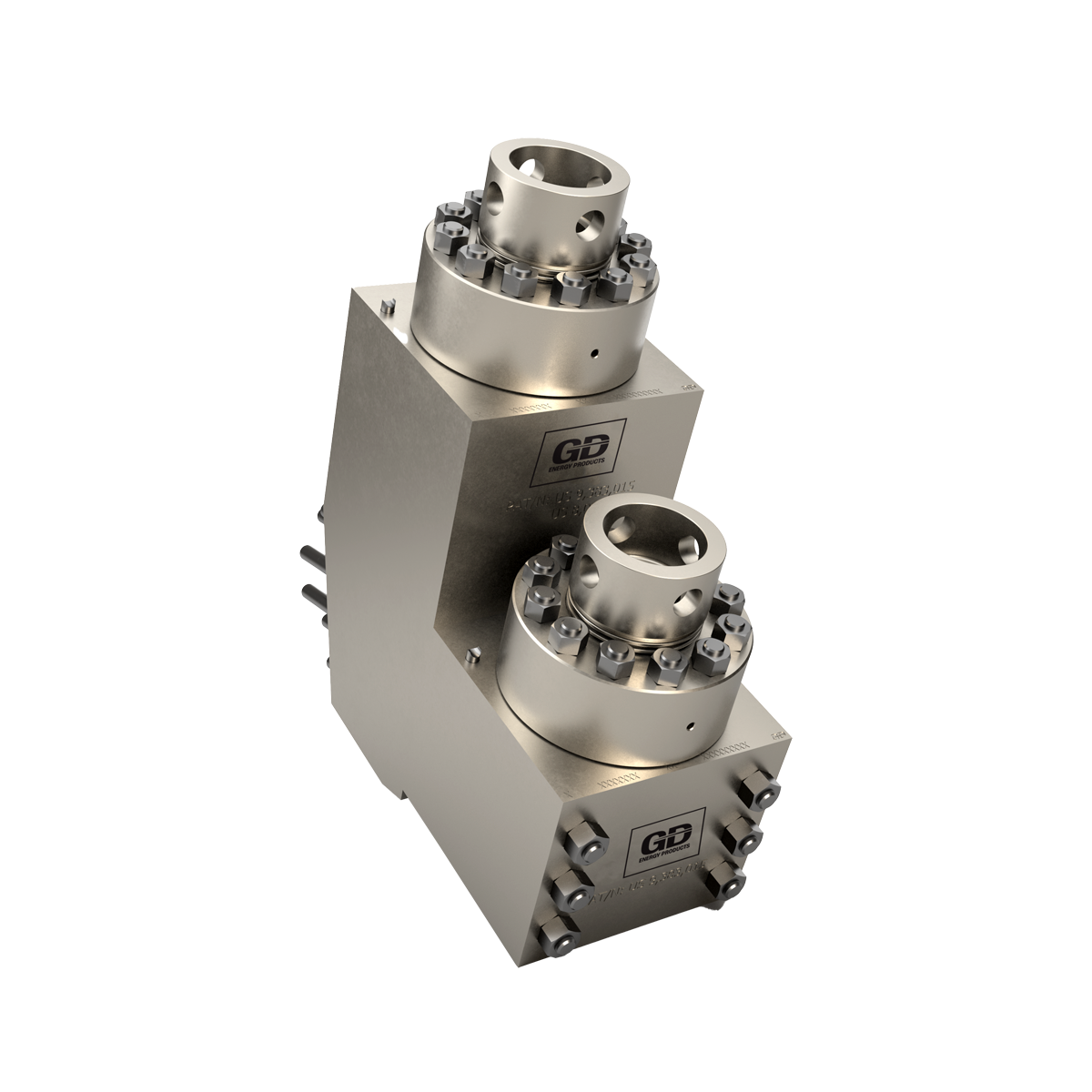
The 2,200-hp mud pump for offshore applications is a single-acting reciprocating triplex mud pump designed for high fluid flow rates, even at low operating speeds, and with a long stroke design. These features reduce the number of load reversals in critical components and increase the life of fluid end parts.
The pump’s critical components are strategically placed to make maintenance and inspection far easier and safer. The two-piece, quick-release piston rod lets you remove the piston without disturbing the liner, minimizing downtime when you’re replacing fluid parts.
The National Board strives to keep information in the hands of website users. Provided here are more than 70 Technical Articles previously published in the National Board BULLETINand/or from the proceedings of past General Meetings.
My invention relates in general to pumps employed for transferring liquids containing the solid materials in suspension, and relates particularly to mud pumps for pumping abrasive materials, such as the fund employed in rotary well drilling operations.
In this disclosure I shall describe my invention as applied to mud pumps employed in the oil fields for pumping lubricating mud mixture into the hole being drilled. This lubricating mud is generally a mixture of clay and water, and therefore contains abrasive materials which cause-very. rapid wear in the moving parts of the mud pump. It is for this reason that replaceable steel liners are provided in the cylinders so that the pumps may have the efliciency thereof renewed. The Wear between the liner and the pump piston is due to the fact that abrasive material adheres to the walls of the liner and passes in between the piston and the liner as the piston reciprocates. This abrasive lubricating mud also adheres to the piston rod and is carried into the packing gland through which the piston rod extends into the pump cylinder. This causes rapid wear upon the piston rod with the result that"a frequent renewal is necessary. The valves of such mud pumps are also subject to the rapid wearing action of the mud and must be"fre-.
Although I am describing nay-invention relative to-this certain type of pump, it will be readily understood that in various industries. pumps are employed for the purpose of transferring liquids containing solid and abrasive materials, and that my invention is also applicable to these other pumps.
It is the principal object of my invention to provide means in a pump for preventing the material, being pumped, from entering between the moving parts, thereby preventing the rapid Wear between these moving parts which is occasionedby such entrance of wear producing materials therebetween. The invention also provides means for clearing the surfaces of the pump valves.
It is a further object of my invention to provide equipment whereby my invention may be employed, which equipment may be attached to and installed in the ordinary type of pumps. I
My invention consists essentially of introducing a flow of steam or other fluid between the frictionally engaging surfaces of the and reventing the entrance of abrasive materia s therebetween. In application to the piston of the pump, the fluid is forced out between the engaging faces of the piston and the cylinder in a forwarddirection as the piston moves forwardly, so that the cylinder Walls are cleared of abrasive materials ahead of the advancing piston. When the piston advances rearwardly, the clearing fluid 1s ejected in a rearward direction, thus Washing the cylinder Walls ahead of the rearwardly advancing piston. When applied to the piston rod, myinvention employs a circularchannel around the piston rod, this channel being disposed at the inner end of the packing box structure. -As the piston rod moves outwardly through the stufiing box, which is in a direction which would ordinarily result in the carrying of abrasive materials into the packing box, a flow of liquid is forced through the annular channel and inwardly along the face of the piston rod, thus washing off the adhering sub-" stances from each succeeding portion of the piston rod surface before it passes into the Fig. 1.
Fig. 5 is a fragmentary view showing in section a portion of a cylinder equipped"with other means for practicing the principles of my invention; the equipment sho-Wn in Fig. 5 being preferablyemployed in high pressure pumps. 7 Fig. 6 is a section taken upon a plane represented by the line 6-6 of Fig. 5.
In Fig. 1, I show a pump having a steam cylinder and "a pumping cylinder 16. Through a connecting rod- 17, the pump"piston 18 is reciprocated by the drive piston 19 which operates in the steam cylinder 15. The steam cylinder 15 has steam ports 20 leading into each end thereof, and discharge ports 21 near each end thereof, which are controlled by a slide valve 23 which is operated in the steam chest 24 by a valve rod 25 connected at 26 to the valve lever 27,- according to customary practice.
Let it be considered that it is desired to apply my invention to the piston rod 17 and stufling box 29 of the pump shown in Fig. 1. A steam pipe 30 may be connected between the steam inlet port-20 and an annular recess 31 formed around the piston rod, this interconnection being accomplished through channels 32 and 33 formed respectively in the walls of the steam cylinder and the pumping cylinder. When the valve 23 is in the position shown in thedrawing so that the steam port 20 at the right hand end of the cylinder 15 is opened, steam enters between the piston 19 and the right hand head 35 of the cylinder 15 and forces the piston l9, and the connecting rod 17 andpiston 18 associated therewith, in a direction indicated by the arrows 36. During this time steam is also being forced throughthe inter-connecting pipe 30 and the annular channel 31 from which it passes around the piston rod 17 into the cylinder 16. This passa e of steam along theface of the piston rod 1 7 has the effect of removing therefrom any adhering materials with the result that the piston rod is washed clean before it passes into the stufiing box 29; therefore, theientrance of abrasive materials into the stufling box is preventedand maximum life of the piston rod attained.
For the purpose of applying the invention to the piston and cylinder of the pump, shown in Fig. 1, channels 38 and 39 may be formed longitudinally in the piston rod 17, the channel 38 opening into-the steam cylinder 15 at 40 and extending to the rearward end of the piston 18 where it connects into an annular channel 41. The channel 39 is open at 42 to the left hand end of the steam cylinder 15 and extends through the piston rod 17 to the forward end of the pump piston 18 where it connects into an annular channel 43. An annular channel 44 is formed at the rearward end of the pump piston 18 in the circumferential face thereof, and an annular channel 45 is similarly formed near the forward end of the pump piston 18. Radial passages 46 connect between the channels 41 and 44 and radial passages"47 connect between the channels 43 and 45. When the pistons are moving in the direction of the arrow 36, steam under pressure between the piston and the head 35 ofthe cylinder 15 is forced through the channel 38 to the annular channel 41 from which it is thencedistributed through the passages 46 to the outer channel 44. From this channel 44- it passes, in the same direction as the movement of the pistons, between the face of the piston and the face of the pump liner 48 and washes the face of the liner 48 clear of adhering substances ahead of the advancing piston. When the pumphas reached the end of its stroke in the direction of the arrow 36, the slide valve i"introduces steam between the steam piston 19 and the head 49 of the cylinder "15, whereupon moving. the
piston in a direction opposite to that indicated by the arrows 36. During this opposite movement, steam under pressure passes through the channel 39, through the chanv nel 43 and passages 47, and is forced from the channel 45 between the face of the piston 18 and the face of the liner 48, in a direction indicated by the arrow50, thus washing the face of the liner 48 on the opposite side of the piston as it moves in a direction opposite to the arrow 36, or in other words, in the direction indicated by the arrow 50. i
" In Fig. 2 of the drawing I show a pump valve structure which may be employed with the mud pump shown in-Fig. 1. This valve structure provides a seat ring which is inserted in the valve-opening 56 provided for this purpose in the division wall 57 of a pump. .This-member 55 has the upper rim ing an annular V-shaped channel 60 formed 7 therein which fits down over the valve seat in the manner shown in Fig. 2. The closure member59 is formed of an outer cup shaped member .60 provided with an annular flange 61 and having an annular groove 62 formed therein. Within this outer member 60 a filler plate 63 having radial channels 64 therein is placed and secured by bolts 66 which hold. the upwardly extending shank 67 of the valve closure member 59 against the member 60-. The shank 67 is cylindrical in form and extends out through a packing box "69 mounted in the outer wall 70 ofthe ump"and has a concentrically disposed tube 71 mounted therein which has a packing Ill) box 72 at the upper end thereof and a lateral outlet73"to which a flexible steam hose or other fluid under high pressure is delivly projecting pins 84 near the upper end thereof which extend into helical channels formed in a stationary block 86 which may be supported-by a bracket 87. Steam ered through the hose 74 into the tube 71. When the valve closure member 59 is raised due to the pressure thereagainst, the valve structure which includes the shank 67, the block 81, and the shaft 79 move upwardly. In moving upwardly, the diametrally extending pins 84 must follow the helical channels 85, thereupon rotating the shaft 79 in :he block 81. Due to the threaded engagement of the shaft 79 with the block 81 as indicated at 80,,the shaft and the valve rod 7 5. attached thereto revolve upwardly relative to the valve structure, with the result that the valve head 76 is raised from.
the orifice 77 and steam allowed to flow through the channels 67 into the annular channel 62 from whence it is distributed, through passages 89, between the V-shaped faces of the closure member 59 and valve seat 55. When the valve structure again lowers, the shaft 79 rotates in the opposite direction with the result that the orifice 77 is again closed by the valve head 76.
I have previously described my invention in operation with a low pressure type of pump. In such pumps the resisting pressure which must be pumped against is lower than the pressure of the steam employed in the steam cylinder and the drive piston and the pumping piston are made of substantially the same size. In this type of pump, steam from the valve chest maybe employed asshown in Fig. 1. In high pressure pumps, however, the pumping piston is. .constructed considerably smaller than the steam or drive piston, so that an increase in pressure may be obtained thereby. In such pumps the pressure in the pump cylinder is much greater than the pressure of the steam employed for driving the pump; therefore, it becomes necessary to use a fluid, or steam,
In Fig. 5, represents a steam pipe leading from high pressure boiler into a valve 91 which connects through a pipe 92 with the annular channel 93 formed around the piston rod 94. The valve 91 is constructed as shown in Figs. 7 and 8, in which 95 represents a body having an inlet passage 96 into which vertical holes 97 are drilled. A revolvable plate 98" operates against the top face. ofthe valve block 95 and has holes 99 therein which cooperate with the holes 97.
axis of the"valve, and discharges through the holes 101 which are also disposed equidistant from-the center of the axis and lie in a plane perpendicular to the plane of the holes 97. The shaft 105 may be rotated upon the face of the block 95 by a lever 106 in such a manner that the holes 99 and --102 are removed from alignment with the holes 97 and 101, as indicated at 107 and 108, thus preventing the flow of steam through the valve. I
".As shown in Fig. 5, the lever 106 has downwardly extending ends 109 and 110 which may be engaged by a block 112 mounted upon the piston rod 94. When the lever 106 has a right hand end thereof raised as indicated by the full lines 114, the valve is opened and steam is allowed to pass through the channel .93. When the left hand end of the lever 106 is raised as indicated by the dotted lines 115, the valve is closed. In Fig. 5, the valve is shown in open position and the piston rod 94 is moving in the direc tion of the arrow 116. During the movement of the piston 94 in this direction, steam is flowing through the channel 93 and the piston rod washed thereby. Up on the block 112 striking the lower end of the downwardly extending portion 110 of the lever 106, the left hand end of the lever is raised and the valve closed, so that no steam will flow during the movement of the piston rod in the direction opposite to the arrow 116. It will be perceived that the flow of steam during this movement of the piston rod is unnecessary as the piston rod is moving away from the gland into the interior of the pump cylinder 118. Upon the iston rod 94 reaching the end of its stroke in the direction indicated by the arrow 120, the block 112, as indicated by the dotted lines 12, raises the right hand end of the lever and thus opens the valve .91 just before the piston rod starts on its return stroke. Therefore, .a How of steam around the piston rod 94 is started before the com- The piston shown in Fig. 5 is of aspecial design, and is so constructed that it operates as a valve for controlling the delivery of steam to thechannels 126 and &
the members 134 and 135 from either end of the member 128. It will be perceived that the frictional engagement of the packin V 136 of the pistons with the cylinder wall 13% will have the tendency to move the outer member 128 upon the inner member 132 within the limits of"the annular recess 130. In Fig. 5, the member 128 is disposed in the position which it assumes when the piston is traveling in the direction indicated by the"arrow 116. The inner member 132 is, therefore, moved forwardly within the outer member and the radial channel 138 coincides with an annular channel 139 formed in the outer member v128, from which channel the steam is delivered through radial passages 140 to the channel 127 so that the steam may flow in the direction indicated by the arrow 116 between the faces of the piston 125 and the cylinder wall 137. Steam is fed to the"piston through a longitudinal channel 142 formed in the piston rod 94. This channel 142 communicates, through a radial passage 143 and a nipple 144, with a flexible steam hose 145 which in turn has connection with the high pressure steam supply. When the piston reaches the ends of its stroke in the direction indicated by the arrow 116, the reverse stroke indicated by the arrow 120 starts. -The first movement within the piston 125 at the start of the reverse stroke is the travel of the inner member 132 within the outer member 128, which is at this time stationary, in the direction indicated by the arrow 120. The radial passage 138 is thereupon removed from alignment with the annular channel 139 and the radial passage is brought into alignment with the annular channel 151 from which the steam is carried through radial passages 152 to the outer channel .126. "This steam is then delivered from thechannel 126, in the direction corresponding to the arrow 120, between the face"of the piston and the face of the cylinder wall 137, with the result that the cylinder wall is washed free of adhering substances ahead of the advancing piston. With this construction of piston, it will be perceived that the flow of steam in either direction is started simultaneously with, or just before, the movement of the piston so that danger of abrasive substancespassing between the piston and the cylinder wall is eliminated.
To prevent the entrance of the material being pumped between the outer member 128 and the inner member 132, flexible rings v Fill the head 71 of the cylinder. For this type of packing chamber I provide a ring member 172 having an inner annular channel 173 and an outer annular channel 174 which are connected by radial passages 176. This ring may be placed in the packing chamber 178 as shown in Fig. 9, and a hole 180 drilled into the wall in a manner to communicate with the outer channel 174. The steam pipe 181 is then threaded into the outer end of the hole 180, as shown, so that steam will be delivered into the outer channel 174,
through the passages 176, and into the inner annular channel 173 from whence it is forced, as indicated by the arrows 184, across the face of the connecting rod as previously described, functioning in the same manner as described relative to the channel shown in Figs. 1 and 5.
It is desirable to use steam as a washing fluid in the practice of my invention owing to the fact that upon the steam coming in contact with the cold liquid or mud contained in the pump cylinder, it will immediately condense to a very small fraction of its original volume as steam and will, therefore, when condensed to water, require but little space within the pump cylinder. The invention is particularly adapted to oil pumps used for transferring oil through long pipe lines such as now employed for delivering oil from the oil fields to the transportation points, as this oil carries in suspension a certain amount of sand and other abrasive materials which are Very detrimental to the reciprocating parts of the pumps em ployed for driving it through the lines.
1. A pump organization comprising walls forming a cylinder; a piston operating in said cylinder; walls of said piston being disposed to form an annular channel near each end of and in the cylindrical face of said piston; and means for forcing a fluid through said channels and between the faces of said piston and said cylinder walls, which means is adapted to lllf) deliver said fluid alternately through said concurring with the direction of travel of said piston.
2. A pump organization comprising walls forminor a cylinder; a piston operating in said cylinder; walls of said piston being disposed to form an annular channel near each end of and in the cylindrical face of said piston; and means for forcing a fluid through said channels and betweenthe faces of said piston and said cylinder walls, which means includes a valve arrangement in said piston adapted to deliver said fluid alternatelyto said channels, said delivery being through the channel disposed at the end of said piston concurring with the direction of travel of said piston.
3. In a pump, the combination of: walls forming a cylinder; a head for said cylinder having a packing member therein; a piston rod operating through said packin member; means for preservmg a flow o 4 fluid over the surface of said rod at the point of entry of said rod into said packing member, and in a-direction opposite to the direction of travel of said rod; a pump piston .on said piston rod; means for introducing a flow of washing fluid between the engaging surfaces of said cylinder and said piston in 1 the same direction as said piston is moving;
valve seats associated with said cylinder; closure members for said valve seats; and means for introducing a flow of washing fluid between the engaging surfaces of said seats and said closure members during theperiods said closure members are raised from said seats.
4. In a pump, the combination of: walls forming a cylinder; a head for said cylinder having a packing member therein; a piston rod operating through said packing member; means for preserving a flow of fluid over the surface of said rod at the point of entry of said rod into said packing member; a pump piston on said piston rod; means for introducing a flow of washing fluid between the engaging surfaces of said cylinder and said piston; valve seats associated with said cylinder; closure members for said valve seats; and means for introducing aflow of washing fluid between the engaging surfaces of said seats and said closure members during the periods said closure members are raised from said seats.

This website is using a security service to protect itself from online attacks. The action you just performed triggered the security solution. There are several actions that could trigger this block including submitting a certain word or phrase, a SQL command or malformed data.

Protects the polymer lining from mechanical damage, prevents blistering in case of high pressure gas service and decompression with vacuum service, supports the wall of the flexible hose. This layer is optional and present only for rough bore hoses, such as for flexible choke & kill lines with TauroFlon™ liner.
Fluid barrier of the flexible line. Protects the hose construction from corrosive and abrasive effects of the conveyed medium. The thickness of lining depends on the internal pressure, the inside diameter and the conveyed medium. The lining material is selected to withstand chemical and heat effects of drilling mud, well effluents, cement slurry, hydraulic fluid or whatever substance is conveyed through the hose.

Titan Oil Tools offers high quality mud pump expendables and mud pump replacement parts for the wide variety of mud pumps, centrifugal pumps found on the world market today. These quality pump parts offer great performance and our pricing will save you money.
We are your oilfield supplier of choice for mud pump spares and mud pump parts: mud pump piston liners and pistons. All mud pump parts can be sourced for fast delivery; Come to us for mud pump liners, pistons, piston rods and parts, pony rods, threaded rings and caps,and more. Try us for duplex and triples pump spares and duplex and triplex mud pump parts, and also valve parts like valve seats. gland nut, and mud pump gaskets.
Mud pump liners may come in chrome, alumina ceramic and zirconia ceramic. Chrome liners and alumina ceramic liners are less costly, their cost of replacement over one year as the chart below shows, is much more than zirconia ceramic liners.
The table below shows a Mud Pump Liner Cost of Ownership which shows a reasonable cost comparison for a rig in continuous service for 36 months. This of course does not include the high cost of maintenance downtime and the cost of labor.
The prices below are based on cost/cylinder. Savings increase when you add up the number of pump cylinders on your rigs and extend the savings to understand the big difference it can make for your budget.

Manufacturer & distributor of water treatment systems. Various products include actuators, agitators, analyzers, brominator assemblies, storage tanks, control panels, feeders, vessels, cartridges, filters, housings, indicators, switches, pumps, strainers, meters, valves, sample coolers, membranes, test kits, colorimeters, reagents, chemicals, coagulants, flocculants, enzymes, metal precipitants, micro-biocides, cleaners, burets, comparator boxes, electrodes, filter papers, funnels, flasks, graduated cylinders, test strips, pipettes, spoons, cabinets & vials. Water treatment equipment including green machines, reverse osmosis & chlorine dioxide feed systems & water softeners are also available. Applications include hot, chilled, steam boiler, domestic & waste water systems & water conservation strategies.


 8613371530291