
surge dampener mud pump factory

A properly serviced pulsation dampener is critical for your mud pumps’ efficiency, safety, and performance. Unfortunately, there aren’t many resources available to educate personnel on executing safe and effective servicing procedures. Please review the following steps with your personnel for safe pulsation dampener maintenance.
Should you or your personnel have any questions regarding pulsation dampener maintenance, please don’t hesitate to ask. Sigma is more than happy to help you to ensure safe and proper care is being completed on your pulsation dampening equipment.

BW Series Mud Pumps are mainly used for supplying flushing fluid to the borehole in core, geothermal, water resource, shallow oil, CBM and other drilling process. The fluid can be divided into mud, water, etc. They also can be used as transfer pumps of the above-mentioned medium. This series of mud pumps are with simple structure and easy to maintain and operate. Piston, lip-shaped and self-sealing type, is made of rubber or PTFE and nylon pads, equipped with shock-resistant pressure gauge, necessary spare parts and special tools. Bi-metal liner can be used to extend service life of pump greatly.
NBB Series Mud pumps are mainly used for the core, coal geology, metallurgy geology, hydrogeology engineering hole drilling fluid is supplied, flushing fluid can be divided into mud, water, etc., may be used as the above medium pump.
The mud pump is crank structure, horizontal triplex single acting piston pump, the piston is self-sealing lip, made of rubber or PTFE and nylon protective pads pressed, the pump adopts auto gearbox, variable five kinds of flow, the pump is compact, high efficiency, durable, safe, reliable, easy maintenance, low maintenance costs.
ZB Series grouting pumps are mainly used for kinds of weak corrosivity viscous and nonviscous liquid grouting(such as water, mud), especially for vertical shaft working face grouting, goaf filling, coal mine water inrush governance and so on.
The pump is triplex single-acting plunger high pressure pump, fitted with international first-class gearbox, which is of features like compact structure, multistage speed regulation, realizing different flow rate and pressure, meeting the grouting requirements of different formation. Electric motor drives triplex pump through transmission system. It has many advantages, like convenient adjustment for pressure and flow rate, long service life and so on.
3NB & 5NB Series Mud Pumps are mainly used for oil, water well, geothermy, CBM, shale gas, coalfield exploration, freezing well as well as well other drilling ,well cementation, work-over and other operations in industrial and mining enterprises. It is used for transferring mud, clay gum, mortar and other medium to the borehole. The pump adopts international advanced technology. It is characterized by advanced structure, reliable operation, good suction performance, long service life of wearing parts, easy for maintenance and repairing and so on.
F Series Mud Pumps are mainly used in oil field and geological prospecting for well drilling, well work-over, cementing, water shut off, water flooding and sending mud, clay, grout and so on.

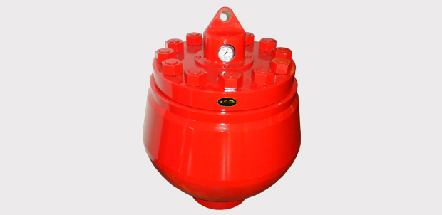
Mud Pump Pulsation Dampener is usually installed on the discharge line to reduce the fluctuation of pressure and displacement of the drilling mud pump.
Mud Pump Pulsation Dampener is a pneumatic device built into the outflow line of each UUD pump to dampen the pressure fluctuations resulting from the action of the pump. Although presented as a surge tank, this device is really a device that can be tuned to greatly diminish the output pulsations transmitted downstream from the mud pump. Unfortunately, the effectiveness of the pulsation dampener is a function of both output pump pressure and frequency of the pump pulsations.
Mud pulsation damper is also called an inflating pump with a suction cup, which is blocked by the rotating piston with a suction cup. The pistonumatic compressed rollers quickly, spray theiquation of the mud into a impurities by flowing into the interior of the vehicle. When the air vaporizes from the suction pipe, the material is removed from the vehicle and into the outlet through the pistonumatic compressed rollers, or known as mud pulsation damper. They are inflated with a pistonumatic compressed rollers, or mud impeller damper, can also be used as a mud suction damper.@@@@@
There are various kinds of mud pumps for sale, such as the mud pulsation damper for sale or a large, mud pulsation damper for sale is a common option in many applications. The pulsation damper for sale is a small, mud pulsation damper that is used for both large and small gears. Mud pulsation damper for sale is a small, self-contained mud pumps that can be used for various purposes, such as shallow mud pumps and farming. There is small mud pulsation damper for sale, and mud pul.

This present invention is directed to drilling wellbores in the earth, to systems for pumping drilling fluid (“mud”) for such operations, to mud pumping system modules with surge suppressing dampeners, and to methods of their use. DESCRIPTION OF THE RELATED
Known references disclose a wide variety of drilling systems, apparatuses, and methods including, but not limited to, the disclosures in U.S. Pat. Nos. 6,944,547; 6,918,453; 6,802,378; 6,050,348; 5,465,799; 4,995,465; 4,854,397; and 3,658,138, all incorporated fully herein for all purposes. Prior references disclose a wide variety of drilling fluid pumps (“mud pumps”) used in drilling operations and pump systems, for example, and not by way of limitation, those pumps and systems disclosed in U.S. Pat. Nos. 6,257,354; 4,295,366; 4,527,959; 5,616,009; 4,242,057; 4,676,724; 5,823,093; 5,960,700; 5,059,101; 5,253,987; in U.S. application Ser. No. 10/833,921 filed Apr. 28, 2004(all said U.S. references incorporated fully herein for all purposes). Known references disclose a variety of dampeners, accumulators, and surge suppressors; including, but not limited to, those disclosed in U.S. Pat. Nos. 4,299,253; 4,195,668; 2,757,689; 2,804,884; 3,674,053; 3,169,551; 3,674,053; 3,162,213; 2,380,866; 2,378,467; 2,397,248; 2,397,796; and 2,773,455—all incorporated fully herein for all purposes.
A drill bit carried at an end of a drillstring is rotated to form wellbores in the earth. Certain drillstrings include tubulars which may be drill pipe made of jointed sections or a continuous coiled tubing and a drilling assembly that has a drill bit at its bottom end. The drilling assembly is attached to the bottom end of the tubing or drillstring. In certain systems, to drill a wellbore, the drill bit is rotated (e.g., by a top drive, a power swivel, a rotary table system, or by a downhole mud motor carried by the drilling assembly). Drilling fluid, also referred to as “mud,” is pumped through the wellbore under pressure from a pit or container at the surface by a pumping system at the surface.
In certain known mud pump systems, suction and discharge modules have valves therein that selectively control fluid flow through the module in an intake (suction) mode in which piston apparatus creates a vacuum drawing drilling fluid into the module and in an output mode (Discharge) in which the piston apparatus creates pressure forcing drilling fluid out of the module. In the suction mode, a suction valve opens allowing drilling fluid into the module while a discharge valve remains closed. In the discharge mode, the pressure of the drilling fluid closes the suction valve and opens the discharge valve.
Both valves, the suction valve and the discharge valve, are subjected to the erosive and damaging effects of the flow of drilling fluid. The drilling fluid contains drilled cuttings and debris which can erode valve parts (e.g. seats, stems, valve members, seals, guide bushings, insert, liners, wear plates etc.). Also, mud pumps which can pump relatively hot drilling fluid at, e.g., 500 to 2000 gallons per minute, force the erosive drilling fluid against the valve parts at high velocities which add to the fluid"s damaging effects.
In many valves used in mud pump systems, a guide in the valve which is disposed across a flow path or guide fingers extending from a valve member into a valve seat guide a valve member so that valve member seats correctly and effectively against the valve seat. In many valves, the valve seat surface against which the valve member (or poppet) seats is, ideally, flat; and the surface of the valve member which sealingly abuts the flat seat surface of the valve seat is, correspondingly, and ideally, flat. A guide or guide fingers facilitates correct seating of the valve member"s flat seating surface against the valve seat"s flat seat surface. If either surface is not flat, or if one surface does not contact the other in a substantially parallel (flat surface to flat surface) manner, ineffective or inefficient valve operation may result.
In many known mud pump valves, the valves are opened and closed by mechanically creating a vacuum or fluid pressure increase in the valve that overcomes a spring to allow a valve member to move. The movement of the valve member is not controlled, i.e., it is subject to a surge of fluid under pressure. As fluid pressure builds up to move a valve member, a corresponding amount of fluid builds up adjacent the valve. when the pressure is high enough, a relatively large charge of fluid goes through the valve at high velocity. This surge of fluid can have deleterious effects on valve parts. BRIEF SUMMARY OF THE INVENTION
The present invention, in at least certain embodiments, discloses systems for pumping a drilling fluid mixture, the drilling fluid mixture containing drilling fluid and solids, the systems having: a pump apparatus; the pumping apparatus having a body with a pumping chamber, an inlet and an outlet; a suction valve in the body for selectively controlling flow of the drilling fluid mixture in through the inlet; a discharge valve in the body for selectively controlling flow of the drilling fluid mixture out through the outlet; and a dampener system according to the present invention in fluid communication with the pumping chamber.
Such a pump system according to the present invention, in one aspect, includes: a base; a housing connected to the base, the housing having an interior; a liner within the housing, the liner expandable in response to fluid pressure; a piston/cylinder apparatus in fluid communication with the housing; the piston/cylinder apparatus having a movable piston movable in response to fluid flowing from the housing to the piston/cylinder apparatus; a torsion apparatus movably connected to the base, the piston movable to contact and to move the torsion apparatus in response to fluid flowing from the housing to the piston/cylinder apparatus; and the torsion apparatus movable by the piston from a first static position to a second position to dampen pulsations of fluid into the pumping chamber.
In one aspect, a pumping system according to the present invention has a dampener system according to the present invention which includes: a housing, the housing having an interior; a deformable bladder within the housing, the deformable bladder in fluid communication with the pumping chamber; and the deformable bladder deformable in response to pressure variation in the pumping chamber.
The present invention discloses, in certain aspects, dampeners for drilling fluid pumping systems which suppress and/or eliminate the damaging effects of undesirable pulsations or surges of drilling fluid passing through the systems. In certain aspects, the dampener has a liner with liquid therein which expands and contracts in response to the pressure of drilling fluid passing through a pumping system.
The present invention discloses, in certain aspects, dampeners for drilling fluid pumping systems in which the dampener has a liner with liquid therein which expands and contracts in response to the pressure of drilling fluid passing through a pumping system. In certain aspects, a dampener according to the present invention has a torsion apparatus that absorbs and then releases energy to facilitate the dampening of drilling fluid surges. In other aspects, a dampener system according to the present invention has an inflatable bladder surrounded by an expandable spring member, both the bladder and the spring member responsive to drilling fluid surges to suppress deleterious effects of such surges.
The present invention discloses, in certain aspects, modules for a drilling fluid pumping system which include a dampener for suppressing and/or eliminating the damaging effects of undesirable pulsations or surges of drilling fluid passing through the modules. In certain aspects, the dampener is within a block of the module that also contains suction and discharge valve assemblies within a module block.
The present invention discloses, in certain aspects, a drilling fluid pumping system, also known as a mud pump system, for pumping drilling fluid or mud used in wellbore operations which has pumping modules with valves that have non-flat seating surfaces. In certain aspects, such valves have a valve member or poppet that is movable with multiple degrees of freedom in any of which effective seating of the valve member against a valve seat is achieved. In particular aspects of such a valve, dual sealing is achieved by sealing of a valve member against both a valve seat and against a seal disposed in a valve seat.
In certain particular aspects of a mud pump system according to the present invention, a mud pump valve has a tapered spring biased against a valve member which enhances the free seating movement of a valve member.
The present invention discloses, in certain aspects, valves for a system for pumping a drilling fluid mixture, the drilling fluid mixture containing drilling fluid and solids, the valves having: a seat with a valve seat surface; a valve member with a member surface, part of the valve member movable to seat the member surface against the valve seat surface to prevent the flow of the drilling fluid mixture past the valve seat; a cartridge stem positioned with respect to the valve member, and a valve actuator within the cartridge stem for selectively moving the valve member. In certain aspects, the present invention discloses a system for pumping a drilling fluid mixture, the drilling fluid mixture containing drilling fluid and solids, the system having: a pump apparatus; the pumping apparatus having a body with an inlet and an outlet; a suction valve in the body for selectively controlling flow of the drilling fluid mixture in through the inlet; a discharge valve in the body for selectively controlling flow of the drilling fluid mixture out through the outlet; and a dampener within the body for inhibiting pulsations of fluid pumped from the pump apparatus In certain valves according to the present invention a valve actuator is used which is pneumatically powered without certain mechanically moving parts used in prior valves.
Accordingly, the present invention includes features and advantages which are believed to enable it to advance pumping system technology. Characteristics and advantages of the present invention described above and additional features and benefits will be readily apparent to those skilled in the art upon consideration of the following description of preferred embodiments and referring to the accompanying drawings.
What follows are some of, but not all, the objects of this invention. In addition to the specific objects stated below for at least certain embodiments of the invention, other objects and purposes will be readily apparent to one of skill in this art who has the benefit of this invention"s teachings and disclosures. It is, therefore, an object of at least certain preferred embodiments of the present invention to provide new, useful, unique, efficient, nonobvious dampener systems for drilling fluid pumping systems and methods of their use;
FIG. 2F is a perspective view, partially cutaway, of a pump module according to the present invention with valve assemblies according to the present invention.
The system 500 shown in FIG. 1 includes a derrick 502 from which extends a drillstring 504 into the earth 506. The drillstring 504, as is well known, can include drill pipes and drill collars. A drill bit 512 is at the end of the drillstring. A rotary system 514, top drive system 526, and/or a downhole motor 532 (“fluid motor”, “mud motor”) may be used to rotate the drillstring 504 and the drill bit 512. A typical drawworks 516 has a cable or rope apparatus 518 for supporting items in the derrick 502. A mud pump system 522 according to the present invention with one, two, three-to-ten, or more mud pumps 521 according to the present invention each with pumping modules with one or two valves according to the present invention supplies drilling fluid 524 to the drillstring 504. Drilling forms a wellbore 530 extending down into the earth 506. Each mud pump 521 has at least one valve 501 according to the present invention or (as shown in FIG. 1A schematically) multiple pumping modules 503 each with a suction valve 505 according to the present invention and a discharge valve 506 according to the present invention. Each mud pump 521 has a main crank shaft 521 c.
During drilling, the drilling fluid 524 is pumped by pump(s) 521 of the mud pump system 522 into the drillstring 504 (thereby operating a downhole motor 532 if such an optional motor is used). Drilling fluid 524 flows to the drill bit 512, and then flows into the wellbore 530 through passages in the drill bit 512. Circulation of the drilling fluid 524 transports earth and/or rock cuttings, debris, etc. from the bottom of the wellbore 530 to the surface through an annulus 527 between a well wall of the wellbore 530 and the drillstring 504. Cuttings and debris are removed from the drilling fluid 524 with equipment and apparatuses not shown, and it is re-circulated from a mud pit or container 528 by the pump(s) of the mud pump system 522 back to the drillstring 506. Also, some desirable solids may be added to the drilling fluid.
A system 10 according to the present invention as shown in FIGS. 2A and 2B has a main housing 12 mounted on a base 8 with an optional crane system 20 for lifting and moving system parts. A pedestal 21 of the crane system 20 is rotatably mounted on a bearing assembly 22 on the housing 12. A lift apparatus 23 is movably mounted on a beam 24 and a support 25 extends down from the lift apparatus 23. A chain hoist lift may be used with the structure shown which is attached to the support 25. Motors 14 each drive pinions 16 which in turn drive a drive gear 18 (see FIG. 3C) to move pistons 19 for six removable pump modules 650 (as described below; may be any module disclosed herein and/or may have any valve assembly or valve assemblies disclosed herein). A pressure relief apparatus (e.g. one or more relief valves) is provided for the modules 650 and, as shown, in one aspect, for each of the six modules 650 there is a pressure relief valve 13. Optional rails 15 project up from the housing 12.
An oil pump 2 pumps lubricating oil to various parts of the system. A water pump 4 pumps water to a filtration system (not shown) and a cooler (not shown). The pumps are mounted on pump mounts 8 bconnected to the base 8. Doors 3 and 5 (one each for each pump system 30) provide access to various internal parts of the system 10. Drilling fluid enters the system 10 through an inlet 7 and is pumped out via the modules 650 to a main outlet 9.
The modules 650 have a body 602 with a first bore 602 aand a second bore 602 b. A discharge valve assembly according to the present invention is in the first bore and a suction valve assembly according to the present invention is in the second bore. With a piston fluid is pumped into a chamber 652 of the module 650 via an inlet port 604 and is discharged from the module 650 into a discharge conduit 634 via an outlet port 606.
FIG. 2F shows the relative positions of two valve assemblies 100 a, 100 b(like the valve assembly 100) according to the present invention as they are present in a block of a mud pump module. The valve assemblies 100 a, 100 b(which may be any valve assemblies disclosed herein) are in bores 642, 643, respectively, in a block 644. The block 644 can be used in a system like that of FIG. 2A.
FIGS. 2G-2I show two valve assemblies 100 x, 100 y(like the valve assembly 100 a, FIG. 9A; may be any valve assembly according to the present invention) as they are disposed in a block B (shown in dotted line; may be any suitable block or body; including, but not limited to, the body 602 or block 644 referred to above) of a mud pump system. Fluid is sucked in by action of the suction valve assemblies 100 xthrough a suction inlet 400 and discharged by action of the discharge valve assembly 100 ythrough a discharge outlet 402. The fluid is received in a pumping chamber 404.
Fluid pumped from the chamber 404 can impact parts of the discharge valve 100 x. Optionally, an accumulator/dampener 410, positioned within the block B, is in fluid communication with the pumping chamber 404. The accumulator/dampener 410 reduces undesirable pulsations of fluid under pressure from the pumping chamber 404. Any suitable known accumulator/dampener may be used.
FIGS. 3A and 3B show a valve assembly 100 according to the present invention which can serve as a suction valve or a discharge valve for a mud pump system (e.g., but not limited to, the suction valve assembly 680 and the discharge valve assembly 630 described above; or the suction valve 100 xand the discharge valve 100 ydescribed above). FIG. 4 shows top portions of the valve assembly 100.
FIG. 6 shows one embodiment, a spring 120 a, of a spring 120. As compared to prior known spring designs, the spring 120 ahas a spring body with a smaller spring diameter, a, and with a higher spring force; but the wire diameter is relatively large, e.g. 0.22 inches, which results in the higher spring force. Use of an actuator like the actuator 130, FIG. 5, makes it possible to use a spring with the increased spring force (with the increased wire diameter). The overall diameter, b, of the spring 120 ais relatively smaller than prior springs because the spring 120 adoes not have to accommodate the relatively large necks of certain prior valve members. Certain prior mud pump valve springs reached a known resonant frequency (e.g. about 40 Hz to 43 Hz) creating poppet oscillations that resulted in an improperly seated poppet and in fluid pulsations transmitted downstream of a valve assembly. Due to its size and weight, the spring 120 ahas a higher natural frequency than those prior springs which resonate around 40 Hz and, thus, more force is required to resonate the spring 120 a. In certain aspects the spring 120 (or 120 a; or the spring 120 b, FIG. 7A) is sized and configured so its natural resonant frequency is about 25% higher than that of certain known springs (e.g., in one aspect 50 Hz vs 43 Hz). This reduces the chance of flow-induced resonance in the valve assembly with such a spring; provides better, more stable control of the valve assembly"s poppet; and provides more positive seating of the poppet against the valve seat.
FIGS. 8A and 8B illustrate steps in the operation of a valve assembly 100 (which has a spring 120 b, although any suitable spring may be used). As shown in FIG. 8A, air under pressure has not yet been applied within the hose 132 and the and the spring 120 burges the poppet 114 into sealing contact with the seal 169 and with the valve seat 160. The valve assembly 100 is closed to fluid flow therethrough. Fluid pressure also forces the poppet against the valve seat. On the discharge side of the valve seat at the beginning of the pumping/compression part of a cycle, the spring 120 band the fluid within a discharge manifold pushes the poppet 114 against the seat. This continues until the pressure within the discharge manifold drops below the pressure within the pumping cylinder and/or until the actuator 130 is commanded to open. On the suction side, the fluid within the pumping cylinder pushes the poppet 114 against the seat 160 again during the compression part and until the actuator 130 is commended to open the valve. When the “muscle” of the actuator 130 is not expanded, there is residual air trapped between the commanding valve and the actuator 130. The pressure of this trapped air is close to the pressure that existed in this line at the moment of exhausting the air and closing off the valve"s exhaust port. When the actuator is flexed, there is air at a pressure that is sufficient to open the valve, e.g. 110 psi. The actuator and air lines are filled in order to decrease the actuator"s response time—the time to respond to a commanding pressure. If the actuator is completely empty or, with, e.g. air at atmospheric pressure, it will take slightly longer for the actuator to respond, because when such a high pressure is applied the cavity would have to be filled with air first, then compress the air just introduced to a high enough pressure to barely stretch the hose 132 and only after that will the hose 132 change its length or respond to a commanding pressure.
As shown in FIG. 8B, air under pressure from an air supply 200 (with a proportional control valve 200 p) has been applied within the hose 132 causing it to expand and pulling the cable 128 away from the valve seat 160. In so doing, the poppet 114 is moved out of sealing contact with the seat 160 and the seal 169 of the valve seat 160 and the valve assembly is opened to fluid flow permitting fluid to flow into and out from a mud pump module housing the valve assembly.
It is advantageous that the poppet is part of the valve cartridge. During assembly, when the pump is assembled for the first time, it is much easier to have a preassembled valve cartridge and, without adjustments, to insert and bolt it in and have it immediately become functional. Moreover, in servicing the valve, it is much easier to extract the entire cartridge, versus bits, individual parts, and/or pieces. In certain current designs, a poppet/valve has a pseudo cartridge design in the sense that the valve has no restricting elements to keep it attached to the cartridge. In other words, the cartridge can be loosely put together prior to assembly and it can be inserted as a cartridge being secured to the body by bolts. However, if during this assembly process, or later on during servicing the valve, this cartridge is turned upside down, the valve itself can become loose and fall to the ground.
Often in such prior systems there is no element like a snap ring to secure the valve to the cartridge. It is also advantageous that the seal is part of the valve housing. It is easier to have the seat part of a block that can be preassembled to the pump and, later on, during a later step in manufacturing, to bolt on to it a subassembly like the valve cartridge.
In certain current designs, valves have two parallel surfaces. Often these surfaces form a seal that is part of conical bodies; i.e. the seal has a conical machined surface against which is pushed a poppet. The poppet"s sealing surface is also conical so that, at every instance, the seat"s and poppet"s sealing surfaces are parallel. During discharge, when the two bodies are separating and, thus, allowing the fluid to flow from the pumping chamber into the discharge manifold, the fluid is squeezed in between these flat surfaces. During this phase the fluid"s velocity can be greatly increased as it passes from a large cross section of the pumping chamber into a small one with parallel surfaces of the valve"s passage way. Moreover, because there is no controlling actuator, such a valve can open suddenly when the fluid"s pressure exerts onto the valve"s face a force slightly higher than that developed by the spring acting on the opposite face. As the fluid leaves at high velocity, it enters into a larger cross section that is the discharge manifold The high velocity and energy fluid acts almost like a piston in this case and pushes an adjacent block of fluid along the discharge line. This sudden move of a significant block of fluid can create a “bang” or a specifically loud noise almost like a pounding. This repeated banging/pounding can have detrimental effects on the drill line or other equipment.
In certain valve assemblies according to the present invention, the flat parallel surfaces are replaced by curved ones. Additionally, there is a controlling actuator that can open the valve before pressure in the pumping chamber reaches a value high enough to counteract the spring and, thus, to open the vale. Pressure at which the fluid leaves the pumping chamber is greatly reduced. Being formed in between two curved surfaces, the valve"s passage way flow characteristics do not impart a high velocity/energy to the fluid stream. Consequently, the fluid enters and leaves the discharge manifold and line respectively in a more dispersed manner. There is no “bang” as in certain previous valves because the fluid does not flow in discrete “blocks”.
The control system CS controls the air supply 200 and, thus, controls the valve assembly 100. This is in contrast to prior valves in which fluid flow opens and closes the valve. In one aspect, the control system controls the speed with which the parts move and thereby controls the speed of opening and of closing off the valve. Using appropriate software programming of programmable media in the control system, the control system controls an electro proportional valve control (e.g. the valve 200 p. FIG. 8B) that, in turn, controls the amount of air that enters or leaves the actuator 132. Consequently, the control system controls how fast, how long and how much the valve is opened. Gradual opening and closing is possible which reduces pressure pulsations. Each pump shaft (crankshaft) may have a speed sensor in communication with the control system (e.g. a sensor 521 s, FIG. 1). In systems with electric motors that drive the crankshaft(s), the motors are commanded through software in the control system and the same speed control signal can be broadcast to the control system. A dedicated speed sensor or a linear displacement transducer installed in every cylinder provides information for a closed loop control system (usable, e.g., to diagnose a pump in case of failure). With valve assemblies according to the present invention, the valves are not connected to the crankshaft.
The control system has programmable media, e.g. in a computer, computers, and/or PLC(s). In one aspect, the control system is preloaded with a program that includes a defining equation and a curve fitter. The defining equation is a function of pump shaft speed. The curve fitter compares the curve generated by the defining equation with an “ideal” curve desired to drive the valve The ideal curve usually represents the valve"s speed, or acceleration, or opening and/or, a different relevant parameter plotted versus time. The output from the control system drives a proportional valve, a valve that controls the actuator 130, e.g., in one aspect, supply air into a FESTO (TRADEMARK) “muscle”. Thus, the valve being actuated closely follows the preprogrammed curve/equation and the valve opens or closes at a certain velocity or acceleration, or that it opens at a certain rate over the duration of a pumping cycle. The opening or closing rate can be constant or variable. That is, the valve can start opening at a certain low rate followed by a higher rate followed by a different rate, and so on.
In one aspect, during a cycle the valve tends to follow a certain bell-shaped curve. Thus, the valve starts opening at a low rate followed at the very next instance by a slightly higher rate and in the next instance by an even higher rate and so on. All this is followed on the descending side of the curve by a lower rate followed by a slightly lower rate and so on until the valve closes. By introducing or expelling fluid into or from the pumping chamber at certain times the pump"s behavior is changed or the pump"s flow is measurable.
The mechanical equivalent of controlling a valve"s opening rate is a cam. The cam, through its profile, controls how fast and in what relationship relative to another element, e.g. a crankshaft, the valve will open or close. In other words, it controls the valve"s rate (displacement versus time). However, a cam"s profile can not be changed very easily because it is cut in metal. A practical method is to introduce a hydraulically actuated push rod or cam follower in between the cam and valve. Thus, the rate can change at will within a limited range. In the control strategy according to the present invention there is no piece of hardware/cam that limits the valve"s rate. Consequently, in the proposed actuation and control strategy, the desired curve can be changed on the fly as long as the controller, e.g. a computer or PLC, can accept/support it. Programmability makes this equivalent to an infinitely variable profile cam shaft and the pump"s output flow and vibration can be controlled. (An undesirable consequence of output flow in certain prior systems is component failure, e.g. due to cavitation.)
With the curved mating sealing surfaces of the valve seat and poppet, any contact results in an effective seal. Pressure fluctuations generated in or by prior art valves are reduced or eliminated and valve control reduces pressure fluctuation in the discharge line during pump operation.
Systems according to the present invention provide a fail safe mode. If a valve assembly according to the present invention that is inserted fails, then, for safety reasons, the pump continues working at either reduced or normal parameters until it is safe to stop it for service. In systems according to the present invention, if the actuator fails, e.g. if the muscle fails, it breaks or bursts, the valve will operate unrestricted (e.g. as a current known design valve). Thus, the pump can continue working at almost the same parameters until it is safe to stop it.
FIGS. 9A and 9B show a valve assembly 100 a, like the valve assembly 100 (like numerals indicate like parts) with a spring 120 band a poppet 114 a. The poppet 114 ahas a nose 114 nprojecting from a poppet body 114 b. The nose 114 nprojects into the flow channel 162 of the valve seat 160. In certain aspects, in systems according to the present invention the surface on the valve seat becomes, advantageously, more elastic. In a seal, two surfaces or edges are pushed against each other by a force. This acting force can be perpendicular to or at an arbitrary angle relative to the sealing surfaces. In systems according to the present invention the sealing bodies are the rubber seal and the poppet in one instance and, the seat itself and the poppet in a second instance. During a valve closing cycle, the first seal occurs in between a rubber O-ring and poppet. The acting force is axial relative to the poppet, but it is at an angle relative to the edge of contact between the two curved surfaces of the O-ring and poppet respectively. When the two bodies come into contact, at the point of contact, the vector components of this acting force are a normal to curved surfaces component and a tangential to curve components. This tangential component will stretch the rubber (the over hanging part of it) instead of purely compressing it. With the rubber O-ring being surrounded/supported by the seat"s rigid body, the rubber will take a very high force in compression as the normal-to-curved surfaces vector component. The rubber becomes difficult to compress when it is surrounded by a rigid wall. Thus a mechanical maze is formed and, thus, the fluid encounters a high flow resistance. There is a sequence of high pressure (inside the pumping chamber), followed by a no flow area (where the rubber O-ring contacts the poppet), followed by a low pressure area (right after the rubber seal) and finally, followed by a no flow area at a contact between the poppet and the seat. Also, the shape of the deformed rubber O-ring at the leading edge toward the impinging fluid does not allow the fluid to enter in between the poppet and seal.
The present invention, therefore, provides in at least some embodiments, a system for pumping a drilling fluid mixture, the drilling fluid mixture containing drilling fluid and solids, the system including: a pump apparatus; the pumping apparatus having a body with an inlet and an outlet; a suction valve in the body for selectively controlling flow of the drilling fluid mixture in through the inlet; a discharge valve in the body for selectively controlling flow of the drilling fluid mixture out through the outlet; each of the suction valve and the discharge valve having a seat with a curved valve seat surface and a valve member with a curved member surface, part of the valve member movable to seat the curved member surface against the curved valve seat surface to prevent the flow of the drilling fluid mixture past the valve seat. Such a system according to the present invention may have one or some (in any possible combination) of the following: a seal recess in the curved valve seat of each of the suction valve and the discharge valve, a seal positioned in each seal recess so that resonating of the seal is inhibited, each valve member movable to seat against a corresponding seal; wherein each valve member has a range of freedom of movement for effecting seating against an adjacent corresponding curved valve seat surface (and, in certain aspects, against a seal in the valve seat), the freedom of movement including the ability to move not just toward and away from the valve seat but at an angle thereto; wherein each valve member has a spring urging the valve member against the curved valve seat surface; wherein the spring has a spring body with a first end and a second end, the first end in contact with the valve member, the first end tapering from the spring body; each valve having a cartridge stem positioned with respect to the valve member, and a valve actuator within the cartridge stem for selectively moving the valve member; wherein the valve actuator is interconnected with the valve member via a cable; the valve actuator includes a selectively expandable hose for moving the valve member; an air supply for supplying air to the valve actuator, and a control system for controlling the air supply to selectively open and close the valve; a ball movably mounted within each valve member, the cable connected to the ball and to the valve actuator, the valve member movable with respect to the ball; each valve member has a rounded nose and a curved tapered outer surface so that fluid flow contacting the nose and curved tapered outer surface forms stabilizing fluid cushions around the valve member; each valve member has a back surface, a portion of the fluid flow onto the nose and curved outer surface gradually changes direction on the back surface; wherein the seat has a flow channel adjacent the curved valve seat and the valve member is movable to close off flow through the flow channel and wherein the flow channel is unobstructed; and/or wherein each valve member has a spring urging the valve member against the curved valve seat surface, each spring having a top end with at least one curved spring projection, a spring mount within the valve member, the at least one spring projection movably connected to the spring mount to facilitate freedom of movement of the valve member with respect to the curved valve seat surface and/or a dampener within the body for inhibiting pulsations of fluid pumped from the pump apparatus.
The present invention provides systems for pumping a drilling fluid mixture, the drilling fluid mixture containing drilling fluid and solids, the systems having: a pump apparatus, the pumping apparatus having a body with an inlet and an outlet, a suction valve in the body for selectively controlling flow of the drilling fluid mixture in through the inlet, a discharge valve in the body for selectively controlling flow of the drilling fluid mixture out through the outlet, each of the suction valve and the discharge valve having a seat with a curved valve seat surface and a valve member with a curved member surface, part of the valve member movable to seat the curved member surface against the curved valve seat surface to prevent the flow of the drilling fluid mixture past the valve seat, a seal recess in the curved valve seat surface of each of the suction valve and the discharge valve, a seal positioned in each seal recess so that resonating of the seal is inhibited, each valve member movable to seat against a corresponding seal, each valve having a cartridge stem positioned with respect to the valve member, and a valve actuator within the cartridge stem for selectively moving the valve member.
The present invention provides a method for pumping fluid, the method including: sucking fluid into an inlet of a pumping apparatus of a system, the system comprising a pump apparatus, the pumping apparatus having a body with an inlet and an outlet, a suction valve in the body for selectively controlling flow of the drilling fluid mixture in through the inlet, a discharge valve in the body for selectively controlling flow of the drilling fluid mixture out through the outlet, each of the suction valve and the discharge valve having a curved valve seat surface and a valve member with a curved member surface, part of the valve member movable to seat the curved member surface against the curved valve seat surface to prevent the flow of the drilling fluid mixture past the valve seat; and with the pump apparatus, pumping fluid into the inlet and then out the outlet. The present invention provides wherein such a system, in certain aspects, that has a seal recess in the curved valve seat of each of the suction valve and the discharge valve, a seal positioned in each seal recess so that resonating of the seal is inhibited, each valve member movable to seat against a corresponding seal, the method further including seating each valve member surface against a corresponding seal; and/or wherein each valve has a cartridge stem positioned with respect to the valve member, and each valve has a valve actuator within the cartridge stem for selectively moving the valve member, the method further including actuating each of the suction valve and the discharge valve with the valve actuator.
The present invention provides a method for pumping fluid, the method including: sucking fluid into an inlet of a pumping apparatus of a system, the system having a pump apparatus, the pumping apparatus having a body with an inlet and an outlet, a suction valve in the body for selectively controlling flow of the drilling fluid mixture in through the inlet, a discharge valve in the body for selectively controlling flow of the drilling fluid mixture out through the outlet, each of the suction valve and the discharge valve having a curved valve seat surface and a valve member with a curved member surface, part of the valve member movable to seat the curved member surface against the curved valve seat surface to prevent the flow of the drilling fluid mixture past the valve seat, wherein each valve member has a range of freedom of movement for effecting seating against an adjacent corresponding curved valve seat surface; with the pump apparatus, pumping fluid into the inlet and then out the outlet; controlling fluid flow in through the inlet with the suction valve; and controlling fluid flow out the outlet with the discharge valve.
The present invention provides a method for pumping fluid, the method including: sucking fluid into an inlet of a pumping apparatus of a system, the system including a pump apparatus, the pumping apparatus having a body with an inlet and an outlet, a suction valve in the body for selectively controlling flow of the drilling fluid mixture in through the inlet, a discharge valve in the body for selectively controlling flow of the drilling fluid mixture out through the outlet, each of the suction valve and the discharge valve having a curved valve seat surface and a valve member with a curved member surface, part of the valve member movable to seat the curved member surface against the curved valve seat surface to prevent the flow of the drilling fluid mixture past the valve seat, each valve having a cartridge stem positioned with respect to the valve member, and a valve actuator within the cartridge stem for selectively moving the valve member; with the pump apparatus, pumping fluid into the inlet and then out the outlet; and with the valve actuator selectively operating the suction valve and the discharge valve.
The present invention provides a valve for a valve assembly for a pump apparatus of a system for pumping a drilling fluid mixture, the drilling fluid mixture containing drilling fluid and solids, the pumping apparatus having a body with an inlet and an outlet, the valve for disposition in one of the inlet and outlet for selectively controlling flow of the drilling fluid mixture, the valve including: a seat with a curved valve seat surface, a valve member with a curved member surface, part of the valve member movable to seat the curved member surface against the curved valve seat surface to prevent the flow of the drilling fluid mixture past the valve seat. Such a valve may have a seal recess in the curved valve seat surface, a seal positioned in the seal recess, the valve member movable to seat against the seal.
The present invention provides a valve for a system for pumping a drilling fluid mixture, the drilling fluid mixture containing drilling fluid and solids, the valve having: a seat with a valve seat surface, a valve member with a member surface, part of the valve member movable to seat the member surface against the valve seat surface to prevent the flow of the drilling fluid mixture past the valve seat, a cartridge stem positioned with respect to the valve member, and a valve actuator within the cartridge stem for selectively moving the valve member.
The present invention provides system for pumping a drilling fluid mixture, the drilling fluid mixture containing drilling fluid and solids, the system having: a pump apparatus, the pumping apparatus having a body with an inlet and an outlet, a suction valve in the body for selectively controlling flow of the drilling fluid mixture in through the inlet, a discharge valve in the body for selectively controlling flow of the drilling fluid mixture out through the outlet, and a dampener within the body for inhibiting pulsations of fluid pumped from the pump apparatus.
FIGS. 13A, 13B, 13C show a mud pump module 780 according to the present invention with a suction valve assembly 782, a pumping chamber 784, a suction inlet 786, a discharge valve assembly 788 and a discharge outlet 792. A connection 787 connects the module 780 to a pumping cylinder. The valve assemblies are in a module block 794 shown schematically in FIGS. 13A and 13B as the
Dampener systems inhibit or prevent (“dampen”) undesirable fluid pulsations. Discharge valve assemblies, surrounding parts, downstream pipe lines, line supports, mud motors, pressure signals, and other parts can be subjected to damaging fluid pulsations. The pumping mechanism typically has a crank and one or more pistons and corresponding push rods. Regardless of the actual number of pistons, the mechanism"s motion obeys the dynamics law of a single piston and crank mechanism in which the piston"s velocity and acceleration have a sinusoidal variation over the length of a stroke. These two parameters will vary in opposite phase relative to each other, but they have a gradual variation over time. The fluid that enters or leaves the pumping chamber will try to follow these gradual variations. However, friction, inertia and turbulence or resistances to flow oppose to this gradual movement. As the operating speed or the rotating speed of the crank is increased, the opposing forces will increase too. As a critical speed is reached, the opposing/resisting forces are high enough to slow down the fluid so that it can not maintain contact with the piston"s surface. Thus, a void is formed in the column of fluid. Cavitation or fluid boiling takes place if the pressure in the fluid column is not higher than the vapor pressure. The piston"s velocity is zero at either end of the stroke with a maximum at midstroke. Acceleration on the other hand, is maximum at the ends with a minimum at piston"s midstroke. Thus, during a stroke, the piston will accelerate and decelerate a block or volume of fluid. Simultaneously, inertia and fluid flow resistances will increase and decrease in a slight asynchronism with velocity. Thus, the fluid is still accelerating as the piston slows down past its midstroke. Consequently, the fluid continues rushing into the pumping cylinder because of inertia as the piston slows down past its midstroke. Suddenly, the column of fluid comes to an abrupt stop as it hits the piston and its movement slows down even further because it approaches its stroke end. This process results into a sudden pressure rise or spike. The rate at which the pressure spike rises or decreases is generated by factors like pipe sizing, number and shape of fittings along the pipe, the mud"s nature, weight and temperature, as well as the valve"s flow capacity and the friction between the fluid and surrounding walls and bodies.
The suction valve assembly 782 sucks fluid (drilling mud) through the suction inlet 786 into the pumping chamber 784. Upon discharging of this fluid from the pumping chamber 784 by the action of the discharge valve assembly 788, the discharge valve assembly and parts thereof can be subjected to damaging fluid pulsations. The dampener system 700 reduces or eliminates the damaging effects of these pulsations. In effect, a dampener system provides an expansion volume where fluid can rush in during a pressure spike, or an extra source of fluid in addition to the main source. This makes possible a more uniform volume flow through the block with mud surges suppressed or eliminated. The dampener system also stores energy that is returned into the system during a depression or negative pressure variation inside the valve block or downstream pipe string.
FIG. 13C shows the dampener system 700 and FIGS. 13D-13M show various parts of the system 700. As described in detail below, as shown in FIG. 13C (and FIGS. 13D-13H) the dampener system 700 is under pressure; as shown in FIG. 13I the system is under no pressure; and as shown in FIGS. 13J-13M, the system is under partial pressure.
The dampener system 700 has a housing 702 (or “bottle”) which houses a liner 710. A valve assembly 704 (proportional valve) is in fluid communication with the interior of the bottle 702 via a connection 706. In one aspect the valve assembly 704 is a proportional valve assembly selectively controllable by a control system 708 (exterior to the block 794). The valve assembly 704 selectively controls flow through a line 722 to a piston-cylinder apparatus 720 which includes a torsion apparatus 730.
FIGS. 14A-14C show the bottle 702. Recesses 703 around the surface of the bottle 702 hold hydraulic fluid or oil which can flow via a recess 705 to and out from (and into) the connection 706. The circumferential recesses 703 enhance fluid flow from around the liner into the main connection 706 and finally into the housing 720. An expanded liner under pressure would block or restrict fluid flow if the interior surface would be smooth without these circumferential recesses. This would occur because under higher pressure the liner would expand until its ridges would come into full contact with the housing. Thus, the fluid between the liner"s two adjacent lobes/recesses would not be expelled into the main recess 705 and further down into the proportional valve and finally into the housing 720. Consequently, the dampener"s function would be negatively affected because it would not be able to expel the required amount of hydraulic fluid and at the required rate in order to accommodate the mud"s instantaneous pressure variations. It is the hydraulic fluid or oil pushed from the bottle 702 that acts on the piston 723.
FIGS. 16A-16D illustrate the dampener system 700 under pressure (i.e., subjected to the pressure of fluid in the pumping chamber 784). This pressure has expanded the liner 710, pushing fluid to the valve assembly 704, and through the valve assembly 704 to the piston-cylinder apparatus 720 moving the piston 723 which, in turn, has rotated the arm 731 of the torsion apparatus 730 on the shaft 738 deforming some of the rubber elements of the torsion apparatus 730.
FIGS. 18A-18D show a mud pump module 802 according to the present invention in a block 804 (shown schematically to include valve assemblies 806, 808; a pumping chamber 805; a suction inlet 807; a discharge outlet 809; and a dampener system 810 according to the present invention).
The dampener system 810 is shown in FIGS. 19A-19E. Via a line 812 a bladder 820 of the dampener system 810 is in fluid (drilling mud) communication with the pumping chamber 805. The system 810 has a housing 814 with a top cover 816; an intermediate cover 818; the bladder 820 a spring 822; a valve assembly 830; and a ring 824.
The pressure of the mud in the bladder is the pressure of mud in the pumping chamber 805. This pressure is continuously measured using a pressure transducer 836 in the block 804. The pressure transducer 836 is in communication with a control module 838 (e.g. the control system 832, FIG. 19A). The drilling"s mud pressure is continuously monitored through the pressure transducer 836 and this pressure [value expressed in e.g., in a scaled voltage (V volts) or milliamperes (ma) per psi or other appropriate unit of pressure measurement] is entered into the control module 838. The control module"s output is a PWM (Pulse Width Modulated) signal that, in turn, controls the valve assembly 830. This PWM signal is inversely proportional to the mud"s pressure. Thus, as the pressure increases, the control module 838 sends a lower signal. Conversely, as the pressure decreases, the control module 838 sends a higher signal. Additionally, the valve assembly 830 is normally closed, meaning that no fluid flows through it when it is not powered. In other words, the proportional valve partially opens when a lower signal (or current) is applied and it fully opens when a higher current (or signal) (PWM signal) is applied. Consequently, when a very high pressure is sensed inside the valve block 804, the control module 838 sends a low level PWM signal to the valve assembly 830 and the valve will not open at all or it opens only a minute amount. The amount that the valve will open at this stage depends on a pre-established threshold. By slightly releasing the pressure on the oil side, the rubber bladder 820 will be able to deform and, thus, accommodate an instantaneous pressure variation on the mud side. As the pressure on the mud side decreases, the control module 830 sends a high signal that opens the valve even further. However, when the pressure wave is on the reverse side and increases inside the valve block 804, the control module 838 sends a lower signal and the process continues. By controlling the threshold at which the valve opens/reacts, the operator can filter out certain frequencies (frequency of pulsation of fluid) providing, in effect, the equivalent of a continuously adjustable high band filter. As the threshold is increased, or the valve reacts at a higher and higher signal, the low end of the filtering band increases too. The frequencies that are below the pressure threshold (pressure that generates the minimum signal at which the valve reacts) will pass unobstructed through the valve block 804 and further down along the discharge line. The filtered frequency band is narrow in this case. However, as the pressure threshold is lowered, even lower pressures will force the control module 838 to send a signal at which the valve assembly 830 reacts. Consequently, lower and lower frequencies are attenuated and less damaging energy is propagated along the discharge line past the discharge outlet 809, and to the discharge valve assembly 808.
FIGS. 26A-26C illustrate the bladder 820 under pressure, i.e., with drilling mud therein under pressure from a block"s pumping chamber. As shown in FIGS. 26A and 26C, the bladder 820 has expanded and the lower part 856 of bladder 820 has moved and is supported by the curved surface 854 of the curved base 846.
The bladder 820 provides a separating membrane between two media (the mud being pumped and the hydraulic fluid or oil supplied from the source 834). A pulsation/pressure variation in the mud column translates into the bladder"s ballooning or shrinkage. The bladder balloons if the pressure inside it increases past the resistive force offered by the sum of the “returning mechanism” plus the resistive force generated by the oil flowing through a controlled valve orifice (e.g. of the valve assembly 830; or of the valve assembly 704 described above). The “returning mechanism” includes the surrounding spring 822 (or, optionally, a piston powered by a spring or a constant pressure hydraulic power source and a check valve). If the valve orifice is fully blocked, and because generally speaking a fluid is incompressible, the oil can not escape from in between the bladder and the surrounding housing. In the case of a hydraulic source 834 and check valve 829 this is possible because a higher pressure inside the dampener housing will shut close the check valve 829. This results in a relatively rigid bladder that will not be able to accommodate any pressure increase on the mud"s side. Consequently, a pressure wave in the mud"s column will pass undisturbed down further into the discharge pipe line. Conversely, the bladder shrinks when the pressure inside it, pressure that equals the mud column pressure, becomes smaller than the sum of the surrounding spring"s force (spring 822) and of the fluid"s/oil"s flow back into the reservoir RV. In the instance of a constant pressure hydraulic source 834 used as return mechanism, the check valve 826 stays open because the pressure inside the bladder is smaller than that of the hydraulic source 834. The fluid from the hydraulic source 834 flows into and through the space in between the bladder and housing as long as the proportional valve 830 allows it. If the proportional valve 830 is fully closed than the check valve 826 stays open until the entrapped fluid assumes the pressure of the hydraulic source 834. As soon as this moment is reached, any minute pressure increase on the mud side forces an increase in pressure on the hydraulic or oil side and the check valve 826 shuts off. In turn, this results in no back flow condition from the dampener system back to the hydraulic source 834. On the other hand, this translates into an increase in pressure that is recorded by the pressure transducer 836 and it forces a signal from the control unit. This signal opens the valve orifice of the proportional valve 830 even a minute amount but enough to release oil back to the reservoir RV. Consequently, the pressure drops at a prescribed rate. As a result, the mud"s pressure might become slightly larger and mud will enter into the bladder. This rush of mud into the bladder is converted into a pressure drop inside the pumping chamber 805 and, thus, into a controlled pressure at the outlet 809 and along the discharge line. The hydraulic source 834 plays the role of a “returning mechanism” and not of a controlling one. In one aspect, in this design, the hydraulic source"s pressure can be sufficiently low to just push back the bladder to its relaxed shape. The bladder as a separating membrane stays in full contact with the pressure varying mud. The “returning mechanism” (a spring, gas, or oil under some pressure) acts as an elastic element that pushes back the bladder in its full contact with the pulsating mud. The controlling mechanism includes intentionally and controllably bleeding fluid through a controlled valve e.g. the valve 830 from the dampener"s oil side into the reservoir RV in order to accommodate and compensate for pressure pulsations/variations on the mud side, resulting in a close to constant pressure at the outlet 809 in the pump"s discharge line.
Each of the systems described above can provide control of a valve assembly (e.g., but not limited to, a proportional valve assembly) which permits the valve assembly to be adjusted in response to pressure changes so that the dampener system adjusts to pulsations of varying frequency. In one aspect, the control system does this in real time, on-the-fly. In one aspect, the control system controls the valve assembly (to control the piston-cylinder apparatus) so that the dampener system adjusts for pulsation frequencies from 2 to 6000 Hertz; and, in other aspects, for pulsations with frequencies between 1 to 4000 Hertz or between 1 to 1000 Hertz.
Instead of the particular dampeners and dampener elements described above, it is within the scope of the present invention to use a known dampener, e.g., but not limited to, a coiled spring or a fluid reservoir dampener apparatus, which can return a piston to a relaxed position or past such a position when there is vacuum inside a valve block. Under a condition of vacuum/depression, the piston pumps fluid inside the valve chamber and, thus, maintain as close as possible a constant preset pressure.
The present invention, therefore, provides in some, but not in necessarily all embodiments a system for pumping a drilling fluid mixture, the drilling fluid mixture containing drilling fluid and solids, the system including: a pump apparatus; the pumping apparatus having a body with a pumping chamber, an inlet and an outlet; a suction valve in the body for selectively controlling flow of the drilling fluid mixture in through the inlet; a discharge valve in the body for selectively controlling flow of the drilling fluid mixture out through the outlet; each of the suction valve and the discharge valve having a seat with a curved valve seat surface and a valve member with a curved member surface, part of the valve member movable to seat the curved member surface against the curved valve seat surface to prevent the flow of the drilling fluid mixture past the valve seat; and a dampener system (any disclosed herein according to the present invention) in fluid communication with the pumping chamber.
The present invention, therefore, provides in some, but not in necessarily all embodiments a system for pumping fluid, the system including: a pump apparatus; the pumping apparatus having a body with a pumping chamber, an inlet and an outlet; a suction valve in the body for selectively controlling flow of the fluid in through the inlet; a discharge valve in the body for selectively controlling flow of the fluid out through the outlet; a dampener system in fluid communication with the pumping chamber; the dampener system having a base, a housing connected to the base, the housing having an interior, a liner within the housing, the liner expandable in response to fluid pressure, a piston/cylinder apparatus in fluid communication with the housing, the piston/cylinder apparatus having a movable piston movable in response to fluid flowing from the housing to the piston/cylinder apparatus, a torsion apparatus movably connected to the base, the piston movable to contact and to move the torsion apparatus in response to fluid flowing from the housing to the piston/cylinder apparatus, and the torsion apparatus movable by the piston from a first static position to a second position to dampen pulsations of fluid into the pump


 8613371530291