
torque converter on mud pump factory
Please send us your inquiry with detail item description or with Model number. If there is no packing demand we take it as our regular exported standard packing. We will offer you an order form for filling. We will recommend you the most suitable model according to information you offered.
We can give you really high quality products with competitive price. We have a better understanding in Chinese market, with us your money will be safe.

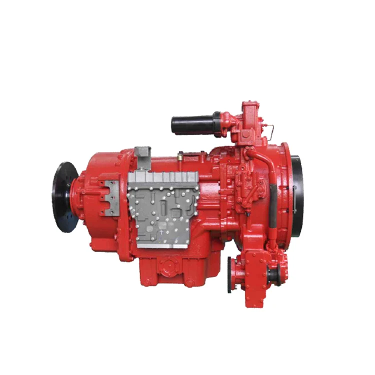
Oil Works Inc., torque converters are designed and built for maximum load performance and operation. Our single and multistage converters are designed for increased peak efficiency with a minimum number of moving parts to optimize service life. Our converters are optimized for specific load applications and protect critical engine and power units by minimizing engine lugging, stalling, and the shock of sudden load changes.
In the oil and gas drilling industry, innovation and adoption of technology have always been required to keep pace with the growing demand for energy.
For the drilling contractor, a reliable and efficient mud pumping system is a critical component of the drilling rig. The mud system is used to flush cuttings up the well bore, power down-hole motors, provide lubrication to the drilling string, and control surface pressure of the well. The drilling industry has a long history of using reciprocating piston pumps powered by a diesel engine and controlled with a clutch, gearbox, or transmission.
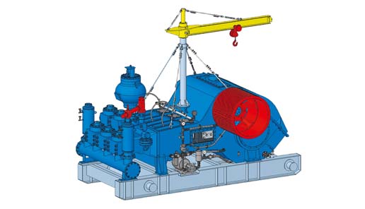
In 1998, Pacific Rim Engineered Products (PREP) developed their first engine mounted transmission with an integral wet clutch, purpose-built for mud pumping. This approach provided tangible benefits over the alternative methods of using air clutches and transmissions adopted from the marine and mobile industrial market place. PREP transmissions are engine mounted directly off the flywheel, and the wet clutch eliminates the power loss typically seen in a torque converter application. PREP’s original transmission design was well received by the industry and has been a success in mechanically driven mud pump packages up to 1300hp.
However, with advances in unconventional drilling techniques, pumping systems require even higher levels of performance. Driven by industry demand for higher discharge pressures and greater productivity while maintaining a compact footprint, PREP developed the X2R 2-speed transmission. The gear train is designed for more powerful engines in order to enable higher pumping pressures and longer component life. The dual-clutch design offers 2 gear ratios to reduce the need for pump liner change-outs and provide a wider operating range of pump speeds and pressures while running the engine at a more efficient speed. For a rig operator, these features directly contribute to increased up-time and reduced fuel consumption.
Traditional methods of using torque converters or air clutches to transmit power often lead to large, heavy and inefficient packages. To offer a compact footprint, PREP optimized the bearing arrangement specifically to accommodate the side load generated by the belt drive and incorporated a new clutch design with a significantly reduced installed length. The X2R’s reduced overall footprint makes it possible to package engines up to 1600HP in a legal transport load configuration.
The X2R’s clutches are serviceable from the rear of the transmission, eliminating the need to remove the transmission from the engine for maintenance. The clutches were also created with a unique design to minimize drag in cold startup. Another feature incorporated in the hydraulic system is the ability to smoothly engage the clutch, or have a soft start of the mud pump, which minimizes shock to the system thereby extending the life of the entire mud pump package. The X2R’s internal lube pump supplies oil for lubrication and clutch engagement, which simplifies packaging and reduces external plumbing. An additional design feature of the transmission is that it uses 15W40 engine oil, common to the diesel engine.
The X2R is supplied with a Transmission Control Module (TCM) that assists the operator in the control and operation of the transmission. The TCM includes a J1939 communication protocol with the engine and an easy-to-use operator interface that displays operating levels and warnings, including oil temperature, clutch pressure, and operating speeds. The TCM has interlocks to inhibit high speed clutch engagement and the ability to automatically disengage the clutch to protect the gearbox from operating outside set parameters.
Over the years, both OEM’s and operators have trusted PREP to develop innovative engineered solutions. PREP’s team specializes in the development of rotating equipment and system designs. Other innovative, power transmission products (up to 6,000hp) can be found in a wide range of industries including transportation, oil & gas, mining and marine.
Continental Emsco Drilling Products, Inc., which consisted of Emsco drilling machinery and Wilson mobile rigs, was purchased by National-Oilwell, Inc on July 7, 1999. To our knowledge, no pumps have been manufactured and sold under the Emsco brand name since National-Oilwell acquired them.
Fairbanks Morse pumps are currently manufactured in Kansas City, Kansas. Fairbanks Morse is a division of Pentair ever since August, 1997 when Pentair purchased the General Signal Pump Group.
Gaso pumps are manufactured by National Oilwell Varco. Gaso was acquired as "Wheatley Gaso" by National-Oilwell in the year 2000. At the time, Wheatley Gaso was owned by Halliburton.
Skytop Brewster pumps are no longer available as new pumps. Skytop Brewster(Cnsld Gold), a unit of Hansen PLC"s Consolidated Gold Fields subsidiary, was acquired while in bankruptcy by National-Oilwell, Inc. in November, 1999.

This website uses cookies to improve your experience while you navigate through the website. Out of these cookies, the cookies that are categorized as necessary are stored on your browser as they are as essential for the working of basic functionalities of the website. We also use third-party cookies that help us analyze and understand how you use this website. These cookies will be stored in your browser only with your consent. You also have the option to opt-out of these cookies. But opting out of some of these cookies may have an effect on your browsing experience.
A torque converter is a type of fluid coupling that transfers rotating power from a prime mover, like an internal combustion engine, to a rotating driven load. In a vehicle with an automatic transmission, the torque converter connects the power source to the load. It is usually located between the engine"s flexplate and the transmission. The equivalent location in a manual transmission would be the mechanical clutch.
The main characteristic of a torque converter is its ability to increase torque when the output rotational speed is so low that it allows the fluid coming off the curved vanes of the turbine to be deflected off the stator while it is locked against its one-way clutch, thus providing the equivalent of a reduction gear. This is a feature beyond that of the simple fluid coupling, which can match rotational speed but does not multiply torque and thus reduces power.
By far the most common form of torque converter in automobile transmissions is the hydrokinetic device described in this article. There are also hydrostatic systems which are widely used in small machines such as compact excavators.
There are also mechanical designs for continuously variable transmissions and these also have the ability to multiply torque. They include the pendulum-based Constantinesco torque converter, the Lambert friction gearing disk drive transmission and the
Industrial power transmission such as conveyor drives, almost all modern forklifts, winches, drilling rigs, construction equipment, and railway locomotives.
A fluid coupling is a two-element drive that is incapable of multiplying torque, while a torque converter has at least one extra element—the stator—which alters the drive"s characteristics during periods of high slippage, producing an increase in output torque.
In a torque converter there are at least three rotating elements: the impeller, which is mechanically driven by the prime mover; the turbine, which drives the load; and the stator, which is interposed between the impeller and turbine so that it can alter oil flow returning from the turbine to the impeller. The classic torque converter design dictates that the stator be prevented from rotating under any condition, hence the term stator. In practice, however, the stator is mounted on an overrunning clutch, which prevents the stator from counter-rotating with respect to the prime mover but allows forward rotation.
Modifications to the basic three element design have been periodically incorporated, especially in applications where higher than normal torque multiplication is required. Most commonly, these have taken the form of multiple turbines and stators, each set being designed to produce differing amounts of torque multiplication. For example, the Buick Dynaflow automatic transmission was a non-shifting design and, under normal conditions, relied solely upon the converter to multiply torque. The Dynaflow used a five element converter to produce the wide range of torque multiplication needed to propel a heavy vehicle.
Although not strictly a part of classic torque converter design, many automotive converters include a lock-up clutch to improve cruising power transmission efficiency and reduce heat. The application of the clutch locks the turbine to the impeller, causing all power transmission to be mechanical, thus eliminating losses associated with fluid drive.
Stall. The prime mover is applying power to the impeller but the turbine cannot rotate. For example, in an automobile, this stage of operation would occur when the driver has placed the transmission in gear but is preventing the vehicle from moving by continuing to apply the brakes. At stall, the torque converter can produce maximum torque multiplication if sufficient input power is applied (the resulting multiplication is called the stall ratio). The stall phase actually lasts for a brief period when the load (e.g., vehicle) initially starts to move, as there will be a very large difference between pump and turbine speed.
Acceleration. The load is accelerating but there still is a relatively large difference between impeller and turbine speed. Under this condition, the converter will produce torque multiplication that is less than what could be achieved under stall conditions. The amount of multiplication will depend upon the actual difference between pump and turbine speed, as well as various other design factors.
Coupling. The turbine has reached approximately 90 percent of the speed of the impeller. Torque multiplication has essentially ceased and the torque converter is behaving in a manner similar to a simple fluid coupling. In modern automotive applications, it is usually at this stage of operation where the lock-up clutch is applied, a procedure that tends to improve fuel efficiency.
The key to the torque converter"s ability to multiply torque lies in the stator. In the classic fluid coupling design, periods of high slippage cause the fluid flow returning from the turbine to the impeller to oppose the direction of impeller rotation, leading to a significant loss of efficiency and the generation of considerable waste heat. Under the same condition in a torque converter, the returning fluid will be redirected by the stator so that it aids the rotation of the impeller, instead of impeding it. The result is that much of the energy in the returning fluid is recovered and added to the energy being applied to the impeller by the prime mover. This action causes a substantial increase in the mass of fluid being directed to the turbine, producing an increase in output torque. Since the returning fluid is initially traveling in a direction opposite to impeller rotation, the stator will likewise attempt to counter-rotate as it forces the fluid to change direction, an effect that is prevented by the one-way stator clutch.
Unlike the radially straight blades used in a plain fluid coupling, a torque converter"s turbine and stator use angled and curved blades. The blade shape of the stator is what alters the path of the fluid, forcing it to coincide with the impeller rotation. The matching curve of the turbine blades helps to correctly direct the returning fluid to the stator so the latter can do its job. The shape of the blades is important as minor variations can result in significant changes to the converter"s performance.
During the stall and acceleration phases, in which torque multiplication occurs, the stator remains stationary due to the action of its one-way clutch. However, as the torque converter approaches the coupling phase, the energy and volume of the fluid returning from the turbine will gradually decrease, causing pressure on the stator to likewise decrease. Once in the coupling phase, the returning fluid will reverse direction and now rotate in the direction of the impeller and turbine, an effect which will attempt to forward-rotate the stator. At this point, the stator clutch will release and the impeller, turbine and stator will all (more or less) turn as a unit.
Unavoidably, some of the fluid"s kinetic energy will be lost due to friction and turbulence, causing the converter to generate waste heat (dissipated in many applications by water cooling). This effect, often referred to as pumping loss, will be most pronounced at or near stall conditions. In modern designs, the blade geometry minimizes oil velocity at low impeller speeds, which allows the turbine to be stalled for long periods with little danger of overheating (as when a vehicle with an automatic transmission is stopped at a traffic signal or in traffic congestion while still in gear).
A torque converter cannot achieve 100 percent coupling efficiency. The classic three element torque converter has an efficiency curve that resembles ∩: zero efficiency at stall, generally increasing efficiency during the acceleration phase and low efficiency in the coupling phase. The loss of efficiency as the converter enters the coupling phase is a result of the turbulence and fluid flow interference generated by the stator, and as previously mentioned, is commonly overcome by mounting the stator on a one-way clutch.
Even with the benefit of the one-way stator clutch, a converter cannot achieve the same level of efficiency in the coupling phase as an equivalently sized fluid coupling. Some loss is due to the presence of the stator (even though rotating as part of the assembly), as it always generates some power-absorbing turbulence. Most of the loss, however, is caused by the curved and angled turbine blades, which do not absorb kinetic energy from the fluid mass as well as radially straight blades. Since the turbine blade geometry is a crucial factor in the converter"s ability to multiply torque, trade-offs between torque multiplication and coupling efficiency are inevitable. In automotive applications, where steady improvements in fuel economy have been mandated by market forces and government edict, the nearly universal use of a lock-up clutch has helped to eliminate the converter from the efficiency equation during cruising operation.
The maximum amount of torque multiplication produced by a converter is highly dependent on the size and geometry of the turbine and stator blades, and is generated only when the converter is at or near the stall phase of operation. Typical stall torque multiplication ratios range from 1.8:1 to 2.5:1 for most automotive applications (although multi-element designs as used in the Buick Dynaflow and Chevrolet Turboglide could produce more). Specialized converters designed for industrial, rail, or heavy marine power transmission systems are capable of as much as 5.0:1 multiplication. Generally speaking, there is a trade-off between maximum torque multiplication and efficiency—high stall ratio converters tend to be relatively inefficient below the coupling speed, whereas low stall ratio converters tend to provide less possible torque multiplication.
The characteristics of the torque converter must be carefully matched to the torque curve of the power source and the intended application. Changing the blade geometry of the stator and/or turbine will change the torque-stall characteristics, as well as the overall efficiency of the unit. For example, drag racing automatic transmissions often use converters modified to produce high stall speeds to improve off-the-line torque, and to get into the power band of the engine more quickly. Highway vehicles generally use lower stall torque converters to limit heat production, and provide a more firm feeling to the vehicle"s characteristics.
A design feature once found in some General Motors automatic transmissions was the variable-pitch stator, in which the blades" angle of attack could be varied in response to changes in engine speed and load. The effect of this was to vary the amount of torque multiplication produced by the converter. At the normal angle of attack, the stator caused the converter to produce a moderate amount of multiplication but with a higher level of efficiency. If the driver abruptly opened the throttle, a valve would switch the stator pitch to a different angle of attack, increasing torque multiplication at the expense of efficiency.
Some torque converters use multiple stators and/or multiple turbines to provide a wider range of torque multiplication. Such multiple-element converters are more common in industrial environments than in automotive transmissions, but automotive applications such as Buick"s Triple Turbine Dynaflow and Chevrolet"s Turboglide also existed. The Buick Dynaflow utilized the torque-multiplying characteristics of its planetary gear set in conjunction with the torque converter for low gear and bypassed the first turbine, using only the second turbine as vehicle speed increased. The unavoidable trade-off with this arrangement was low efficiency and eventually these transmissions were discontinued in favor of the more efficient three speed units with a conventional three element torque converter.
As described above, impelling losses within the torque converter reduce efficiency and generate waste heat. In modern automotive applications, this problem is commonly avoided by use of a lock-up clutch that physically links the impeller and turbine, effectively changing the converter into a purely mechanical coupling. The result is no slippage, and virtually no power loss.
The first automotive application of the lock-up principle was Packard"s Ultramatic transmission, introduced in 1949, which locked up the converter at cruising speeds, unlocking when the throttle was floored for quick acceleration or as the vehicle slowed. This feature was also present in some Borg-Warner transmissions produced during the 1950s. It fell out of favor in subsequent years due to its extra complexity and cost. In the late 1970s lock-up clutches started to reappear in response to demands for improved fuel economy, and are now nearly universal in automotive applications.
In high performance, racing and heavy duty commercial converters, the pump and turbine may be further strengthened by a process called furnace brazing, in which molten brass is drawn into seams and joints to produce a stronger bond between the blades, hubs and annular ring(s). Because the furnace brazing process creates a small radius at the point where a blade meets with a hub or annular ring, a theoretical decrease in turbulence will occur, resulting in a corresponding increase in efficiency.
Overheating: Continuous high levels of slippage may overwhelm the converter"s ability to dissipate heat, resulting in damage to the elastomer seals that retain fluid inside the converter. A prime example in passenger cars would be getting stuck in snow or mud and having to rock the vehicle forward and backward to gain momentum by going back and forth from drive to reverse using significant power. The transmission fluid will quickly overheat, not to mention the repeated impacts on the stator clutch (next topic). Also, overheating transmission fluid causes it to lose viscosity and damage the transmission. Such abuse can in rare cases cause the torque converter to leak and eventually stop functioning due to lack of fluid.
Stator clutch seizure: The inner and outer elements of the one-way stator clutch become permanently locked together, thus preventing the stator from rotating during the coupling phase. Most often, seizure is precipitated by severe loading and subsequent distortion of the clutch components. Eventually, galling of the mating parts occurs, which triggers seizure. A converter with a seized stator clutch will exhibit very poor efficiency during the coupling phase, and in a motor vehicle, fuel consumption will drastically increase. Converter overheating under such conditions will usually occur if continued operation is attempted.
Stator clutch breakage: A very abrupt application of power, as in putting the transmission in neutral and increasing engine RPMs before engaging a gear (commonly called a "neutral start"), can cause shock loading of the stator clutch, resulting in breakage. If this occurs, the stator will freely counter-rotate in the direction opposite to that of the pump and almost no power transmission will take place. In an automobile, the effect is similar to a severe case of transmission slippage and the vehicle is all but incapable of moving under its own power.
Blade deformation and fragmentation: If subjected to abrupt loading or excessive heating of the converter, pump and/or turbine blades may be deformed, separated from their hubs and/or annular rings, or may break up into fragments. At the least, such a failure will result in a significant loss of efficiency, producing symptoms similar (although less pronounced) to those accompanying stator clutch failure. In extreme cases, catastrophic destruction of the converter will occur.
Ballooning: Prolonged operation under excessive loading, very abrupt application of load, or operating a torque converter at very high RPM may cause the shape of the converter"s housing to be physically distorted due to internal pressure and/or the stress imposed by inertia. Under extreme conditions, ballooning will cause the converter housing to rupture, resulting in the violent dispersal of hot oil and metal fragments over a wide area.

The oil and gas industry (also referred to as the petroleum industry) is indicative of exploration, refining, extraction and transporting processes. In addition, this industry includes petroleum products and the marketing of them. With gasoline and fuel oil being the largest volume products, the oil and gas industry is vital to many other industries.
Since 1983, K & L Clutch and Transmission has provided clutch and transmission for equipment in the oil and gas industry, offering a vast array of industry-specific services and products specifically for transmission and clutch repair.
This reciprocating plunger device is used to circulate drilling fluid while under high pressure. Mud pumps circulate drilling fluid (or mud) on a drilling rig. Mud pumps are considered an important piece of oil drilling equipment.
Pump jacks, also known as pumping units, horsehead pumps or jack pumps, are overground drives used for reciprocating piston pumps for an oil well. Used to lift liquid mechanically out of an oil well if there’s not sufficient pressure at the bottom of the hole to allow oil to flow up to the surface, they are commonly used in oil-rich areas.
Well servicing rigs are designed to increase and optimize production at existing wells and range from 200 to 900 horsepower. These rigs are utilized in the routine maintenance and repair of gas and oil wells and in addition, are used during shallow drilling operations.
Wireline units are designed to be used in the oil and gas industry for slick-line or e-line service work during open / cased hole logging services in oilfield environments. Wireline units are critical during open hole logging operations which involve the deployment of specialized tools into freshly drilled oil wells.
Brakes ““ Brakes create heat by converting kinetic energy from friction. In the simplest terms, well-working brakes are necessary to halt motion and to operate heavy equipment properly.
Power Take-Offs ““ Also referenced to as PTOs, power take-offs are responsible from garnering power from an operational power source. Through this process, power take-offs are able to supply power to machines that are separate from the power source.
Torque Converters ““ The primary job of a torque converter is to transfer moving power from an electric motor to a rotating driven load. These products are able to multiply torque in the event of a great differing of input and output speed.
Please contact K&L Clutch and Transmission for road building equipment, transmission for equipment in the oil and gas industry or air clutch equipment at (817) 627-0129.
Torque converters appear to be a bunch of mysterious whirlwind motion inside a spinning shell that transmits an engine"s power to the transmission and rear wheels. Although they seem complex, torque converters are actually very simple in scope. What"s more, it really is easy to choose the right one because ATI Performance Products makes it all simple to understand.
What does it all mean? What is stall speed? What is the difference between stall speed and flash? How does a locking torque converter work? How does a torque converter multiply torque? What makes torque converters fail? The questions are endless. However, the answers are simple.
The humble torque converter is little more than a fluid coupling, a hydromechanical connection where we enlist fluid to do our work via an impeller, stator, and turbine whirling around inside a shell. Think of a torque converter like you would a water wheel in a saw mill. Fluid in motion moves a turbine (water wheel), which drives a shaft that drives a series of machines and equipment. Where the torque converter differs from a water wheel is in how it transfers power. The engine"s crankshaft spins the finned impeller inside the shell, getting transmission fluid in motion around the inside of the shell. Fluid in motion passes through the stator (stationary fins mounted on a one-way clutch) to the turbine, which is connected to the transmission"s input shaft and forward clutch assembly. There is a roller clutch (also called a one-way clutch) on which the stator is mounted, which allows stator rotation one way, but not the other.
Torque multiplication happens when we vector fluid from the impeller through the stator in the middle to the turbine at the transmission"s input shaft. We"re taking transmission fluid and whirling it around the perimeter of the shell, which creates velocity (speed), fluid in motion, and channeling it through the finned stator. As fluid passes aggressively through the stator it picks up even more velocity as it flows through the turbine. What you get with this interaction is roughly two and half times the torque your engine makes. This means 300 lb-ft of torque at the crankshaft becomes two- to two and a half times that number under acceleration.
While the engine is driving the torque converter shell, it is also driving a hollow output shaft tied to the transmission"s front pump, which provides the hydraulic pressure necessary to both control shift function and provide lubrication throughout the transmission. Hydraulic pressure serves to engage clutches and bands as a part of shift function. Not all automatic transmissions have bands. Some are entirely comprised of clutches.
Where torque converters become more complex is when you have a lockup feature with a clutch inside the converter to improve efficiency and eliminate the kind of slippage we experience with a torque converter. When the clutch engages, torque multiplication ends and there"s a direct connection between the engine"s crankshaft and the transmission"s input shaft. This is when an automatic transmission resembles a manual transmission. There are both three-speed automatics and overdrive automatics with locking torque converters. Most overdrive automatics go into converter lockup in overdrive while three-speed automatics can go into lockup in any gear range.
rque converters is stall speed and flash. Stall speed is that rpm range when your engine begins to move the vehicle. The converter "stalls" or "loads" and applies torque to the transmission"s input shaft when it reaches a given rpm range. "Flash" is a more complex answer rooted in vehicle type and weight, engine size and type, and the kind of driving you intend to do. Harvey Baker of ATI Performance Products tells us flash is an involved element that would take pages to explain. Suffice it to say, flash has a different meaning on the street than it does in racing. Your focus in choosing a torque converter needs to be stall speed.
Never put your vehicle to the test with hard power braking at wide-open-throttle sitting still to ascertain stall speed because you"re bound to do a certain amount of engine and transmission damage in the process. Stall speed is best checked with the vehicle in gear at a crawl before nailing the throttle. Stock torque converters generally have a stall speed around 1,800-2,000 rpm. Higher stall speeds become necessary when horsepower and torque happen at higher rpm ranges. You want stall speed and maximum engine torque to happen around the same rpm range. This means if maximum torque rolls in round 3,500 rpm this is where stall speed should be. When you launch, torque will segue to horsepower as your transmission navigates the gears.
We carry the highest quality torque converters for high performance and high power diesel trucks. Shop here to get top torque converters from leading manufacturers at the best prices. Scroll down to watch how a torque converter works, and what one will work best for your needs!

We can provide remote control box in the driller room, please provide the line length, layout and specific switch Settings and name, we can use stainless steel or iron control ,we can design one control system control one mud pump package, or one control system control two mud pump package or more, please contact tiger sales engineer to know your requirement.
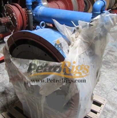
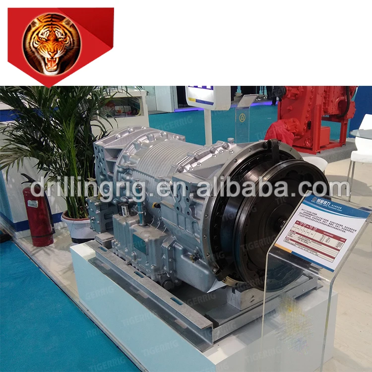
We have a lot of jichai gearbox in stock supply, such as BY620,BY720,BY670 delivery time is 7 days after you confirm the drawing and color, welcome online payment in Alibaba. Book gearbox delivery time is :25-30 days after 30% payment.
If the order is mud pump unit, you have to pay 100% for the gearbox , then we can get the gearbox from jichai, jichai plant plant is very close our plant only 2 days transport to our tiger plant.
After the execution of contract, the user may not have to be present for the gearbox test. We will issue the test report and data for your reference, also take videos and pictures for you.
For the mud pump unit test, we need to test after connecting the driving engine, so we need the user to be present to participate in the field test. After the test is qualified, please pay 10% final payment. We will deliver the pump unit to Shanghai port.

Distributor of wear parts and accessories for dozers, excavators, wheel loaders, motor graders, scrapers, pavers, track loaders, skid steer machines and ground moving and construction equipment. Products include grader blades, snow plow blades, carbide bits, rubber and steel tracks, sprockets, chains, screeds, augers, pads, idlers, rollers, bearings, gaskets and seals. Engine parts such as cylinder heads, pistons, rods, oil and water pumps, camshafts, turbochargers, starters, alternators, manifolds, hydraulic cylinders, radiators and coolers are available. Repair parts, ground engaging tools, drive train parts and heavy equipment undercarriage parts also provided.

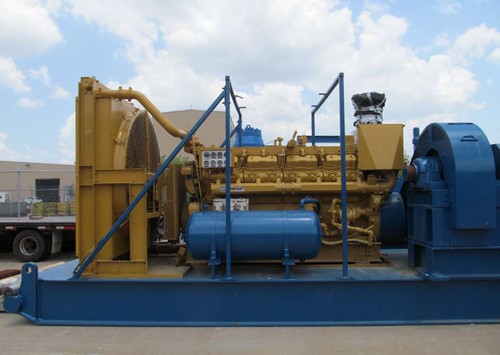
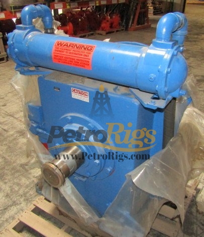
PUMP PACKAGE POWERED BY A CAT D3512 HD WITH A C300-100 NATIONAL OILWELL TORQUE CONVERTER. WEATHERFORD MODEL MP-13, 1300 HP TRIPLEX MUD PUMP, 7X12 INCH, 120 RPM, PULSATION DAMPENER AND SUCTION SCREEN, 8 INCH SUCTION, CHARGING PUMP WITH ELECTRIC MOTOR, MUD GAUGE, AIR TANK FOR AIR STARTER, DIESEL FUEL DAY TANK, ON 10X35 MASTER SKID.
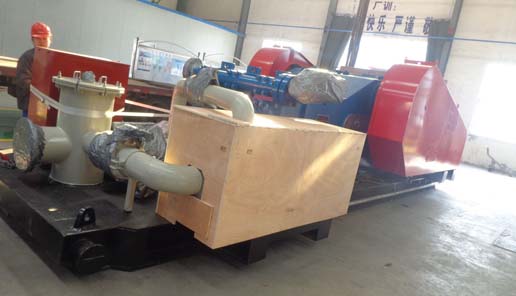
The new F500 mud pump package has been assembled and will be shipped to Azerbaijan oilfield drilling work site by BEYOND client. This is the eighth set of mud pump ordered by him who have cooperated with us for 12 years since we just start to do export business.
This F500 mud pump complies with American API standards. So the spare parts are commonly used internationally. The advantages of F series mud pump are strong structure, small volume and good performance, adapt to oil field high pressure, large displacement and other drilling process requirements.
And we are the exclusive foreign market agent of SHENGLI mud pump factory, not only the good quality we provide but also the super competitive price among China domestic market.
After more than 10 years accumulation of experience, we can design and customize different power matching mud pump packages according to different drilling requirements of clients, and reduce the cost budget for them.


 8613371530291