
vertical effluent handling mud pump free sample

Explore a wide variety of vertical mud pump on Alibaba.com and enjoy exquisite deals. The machines help maintain drilling mud circulation throughout the project. There are many models and brands available, each with outstanding value. These vertical mud pump are efficient, durable, and completely waterproof. They are designed to lift water and mud with efficiency without using much energy or taking a lot of space.
The primary advantage of these vertical mud pump is that they can raise water from greater depths. With the fast-changing technology, purchase machines that come with the best technology for optimum results. They should be well adapted to the overall configuration of the installation to perform various operations. Hence, quality products are needed for more efficiency and enjoyment of the machines" full life expectancy.
Alibaba.com offers a wide selection of products with innovative features. The products are designed for a wide range of flow rates that differ by brand. They provide cost-effective options catering to different consumer needs. When choosing the right vertical mud pump for the drilling project, consider factors such as size, shape, and machine cost. More powerful tools are needed when dealing with large projects such as agriculture or irrigation.
Alibaba.com provides a wide range of vertical mud pump to suit different tastes and budgets. The site has a large assortment of products from major suppliers on the market. The products are made of durable materials to avoid corrosion and premature wear during operations. The range of products and brands on the site assures quality and good value for money.
Due to increasing water scarcity, the requirements for trade effluent discharge consent and rising cost of trade effluent disposal, plant owners are seeking ways to reduce the cost of wastewater disposal and as part of working towards becoming carbon neutral, monitoring waste output and how it can be reduced.
In addition to social and ethical reasons for monitoring, there can be hefty fines if rules are broken and industrial plants are found to have discharged trade effluent at levels above, they have consent for, and outside agreed quality limits polluting the surrounding area. There are strict guidelines to follow, however there are also huge benefits for the plant owners from monitoring in the form of protecting profits.
A pump is required to extract the water for sampling, quite often the samples required are small meaning specialist dosing pumps are needed. It can be difficult to accurately select a pump for these applications as contaminants are unknown, sometimes forming viscous abrasive sludges or leading to high amounts of dry solids content therefore causing clogging or dry running. If a wastewater producer is involved in metal processing, it is essential any pump involved in monitoring is free of metal so as not to interfere with readings from the process medium.
It is common for the pump to be situated above the water surface where levels can change, therefore requiring a self-priming pump. The complicated conditions and variation in water quality often necessitates costly protection devices for the unit installed, these are not always 100% effective and the sophisticated pump designs can lead to expensive part costs and large maintenance bills as they can also be difficult to maintain.
This project involved supplying remote sampling pumps for 24/7 monitoring across 15 different sites in the UK. The customer samples dirty water and has experienced issues with other pump technologies due to low water levels causing dry running. In addition to this, there are other complications such as fluctuating inlet pressures and various types of solids including twigs, grass, and mud.
The client preferred a low maintenance and reliable pump solution due to the remote location of the pumps. They required the units to self-prime, handle solids without clogging and be quick and low cost to maintain in the event of a failure. The units operate at around 500L/hr at low pressures and are controlled remotely across the various testing locations, while away from site they need to be able to alter the speed, monitor the pump condition and reverse the flow in the event of clogging.
We specified 14 qty AMP 16 peristaltic pumps for this project as they provide all the benefits this customer requires. They are consistently reliable in slurry, sludge and wastewater applications while also being simple and cost effective to maintain.
Peristaltic pumps, also known as hose pumps, are simple in design as there is only one wearing internal part, the hose. This is easily and quickly replaced without the requirement of special training or tools; this is an excellent benefit for 24/7 remote applications such as this where excess amounts of downtime cannot be tolerated and where often only low skilled staff are available to perform urgent repairs.
Being simple to maintain does not detract from their dependability and robustness, the absence of mechanical seals allows the pump to run dry indefinitely without damage. Operating at low speeds with the peristalsis pumping action facilitates self-priming and the handling of viscous fluids without issues. As the unit can run dry it also guarantees sample quality as the pump can be completely emptied of fluid before the next sample is taken preventing cross contamination.
The absence of valves and seals means that solids up to the size of the internal diameter of the hose can be passed without clogging, in addition to this the gentle pumping action does not alter the state of shear sensitive fluids or damage delicate solid particles. In the unlikely event of clogging, the unit is reversible meaning the pump can be unclogged by simply reversing the flow, another big benefit for this customer remotely operating across so many sites.
Peristaltic pumps have all the benefits of positive displacement pumps with few of the weaknesses, their operation is slip free meaning they can handle both thin and viscous fluids without losses in efficiency, other pump designs can experience slippage with varying viscosities that can lead to differing performances.
We installed all the pumps with hose leakage detectors to reduce plant downtime as much as possible, this is a particularly useful feature for the client as it sends a signal to a control panel if the internal hose ruptures. The engineers then know immediately that the hose needs replacing, and they can act on it quickly and have the unit up and running straight away.
The modern roller design increases efficiency and reduces power consumption by up to 30% compared to other traditional peristaltic pump designs, this also leads to increased hose life and even with 24/7 operation the sites can expect years of trouble-free operation with maintenance and lubrication intervals as far as 12 months apart.
After trialling our AMP 16 pump the customer was convinced and ordered an additional 14 units complete with single phase inverter, hose leakage detector and forced air cooling for operating the motor at very slow speeds when extremely low flow rates are required. This unit facilitates a wide range of flow rates by simply altering the speed, a truly reliable and flexible pump solution for their sampling systems.

Dealing with a clogged pump or pipe is never fun. When the blockages involve sewage and other forms of hazardous waste, routine cleaning chores can become a health hazard. Keeping sewage pump stations and treatment plants running smoothly not only saves money, but it also results in higher job satisfaction among the maintenance team, in addition, to help keep the city running smoothly.
It’s not just the unusually large size of solids that make sewage pumping and wastewater treatment handling so challenging. The nature of the solids in question also plays a role in the likelihood of the formation of clogs. Sewage from toilet facilities is particularly likely to form clogs due to the use of toilet paper and flushable wipe and feminine products. While most toilet papers break down by the time the material reaches a sewage pump, flushable wipes tend to clump together due to their long, thin shape and tough fibrous texture.
Combine these easy to snag solids with malleable mixtures that act like clay when caught against another item and you can easily understand why sewage pumps can bind up so quickly and completely. Even with care, many sewage pumping stations find themselves replacing their primary pumps annually or even every few months due to the intense amounts of wear and tear on the equipment. If the pumps manage to run for a few years without replacement, it’s usually due to extensive cleaning routines that involve many hours of extra labor per month. Chopper pumps are ideal for sewage processing applications because the internal chopping mechanism breaks up large solids before they reach the pump. Add smaller solids to the large internal capacity of the EDDY pump design and you have a winning combination for avoiding sewage clogs in even the most challenging systems.
This rig features a Mission 4-by-5 centrifugal pump. Courtesy of Higgins Rig Co.Returning to the water well industry when I joined Schramm Inc. last year, I knew that expanding my mud pump knowledge was necessary to represent the company"s mud rotary drill line properly. One item new to me was the centrifugal mud pump. What was this pump that a number of drillers were using? I had been trained that a piston pump was the only pump of any ability.
As I traveled and questioned drillers, I found that opinions of the centrifugal pumps varied. "Best pump ever built," "What a piece of junk" and "Can"t drill more than 200 feet with a centrifugal" were typical of varying responses. Because different opinions had confused the issue, I concluded my discussions and restarted my education with a call to a centrifugal pump manufacturer. After that conversation, I went back to the field to continue my investigation.
For the past eight months, I have held many discussions and conducted field visits to understand the centrifugal pump. As a result, my factual investigation has clearly proved that the centrifugal pump has a place in mud rotary drilling. The fact also is clear that many drilling contractors do not understand the correct operational use of the pump. Following are the results of my work in the field.
High up-hole velocity - High pump flow (gpm) moves cuttings fast. This works well with lower viscosity muds - reducing mud expense, mixing time and creating shorter settling times.
Able to run a desander - The centrifugal"s high volume enables a desander to be operated off the pump discharge while drilling without adding a dedicated desander pump.
6. Sticky clays will stall a centrifugal pump"s flow. Be prepared to reduce your bit load in these conditions and increase your rpm if conditions allow. Yes, clays can be drilled with a centrifugal pump.
7. Centrifugal pumps cannot pump muds over 9.5 lbs./gal. Centrifugal pumps work best with a 9.0 lbs./gal. mud weight or less. High flow rate move cuttings, not heavy mud.
The goal of this article has been to increase awareness of the value of the centrifugal pump and its growing use. Although the centrifugal pump is not flawless, once its different operating techniques are understood, drilling programs are being enhanced with the use of this pump.
If you wish to learn more, please talk directly to centrifugal pump users. Feel free to call me at 314-909-8077 for a centrifugal pump user list. These drillers will gladly share their centrifugal pump experiences.

Sludge, slurry and sewage—three topics that aren’t a subject of everyday “pleasant” conversations. Any of these words conjures images of yucky goo, germs, and debris. But dealing with these fluids is a fact of life, and you need the right kind ofsubmersible pumpto handle the heavier load.
Having the right pump helps considerably with handling sludge and slurry safely. But with many brands and types of pump on the market, what kind of heavy-duty pump do you need to handle the workload?
Sludge pumps and slurry pumps are often considered interchangeable, but they do have slightly different functions. Both sludge and slurry are fluids with a high percentage of solids, but sludge is softer and thicker. Slurry is thinner and flows through the pipes more easily.
This article explains everything you need to know about sludge and slurry pumps, including the difference between a sludge pump and a slurry pump, and when you might need one.
Sludge has a thick texture that may be very viscous or sticky, making it difficult to pump. However, with a higher percentage of solids, it is more compact and can facilitate the disposal of waste products.
Being easier to pump, slurry is the preferred output where waste needs to be transported in liquid form. Being distributed in a liquid suspension, slurries can make it easier to relocate and dispose of waste products in the mining and construction industries.
Both sludge and slurry are mixtures of liquid and pulverised solid waste, but they are not the same. Sludge has a heavier consistency, like thick mud, while slurry is thinner and less viscous.
The main difference between sludge and slurry is the texture, rather than the composition of the fluid. Both slurry and sludge contain solids such as sand, mud, metals, sediments, and other particles within the liquid. They may be organic (like sewage) or non-organic.
Sludge is a thick and viscous fluid, and may be sticky, while slurry is thinner and flows more easily. This means that pumping requirements can vary significantly between these two fluids, and is also influenced by the type of particles found in the material.
The purpose of the sludge pump is to move sludge through sewer lines or other systems. Sludge can be heavy and often abrasive and corrosive; therefore, these pumps need to be high-powered. The heavier the sludge, the more horsepower that is required.
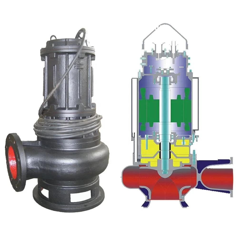
Centrifugal pumpsare commonly used thanks to their ability to pump effluent reliably. A centrifugal pump consists of a rotating impeller that converts electrical energy from the motor into kinetic energy. The kinetic energy is then converted to pressure, which creates the flow of the sludge through the pump.
These pumps can handle particles up to the size of sand, and flow rates can go as high as thousands of litres per second. However, these pumps cannot generate pressures higher than 1000 psi.
Positive displacement pumps work differently. While centrifugal pumps use continuous energy to increase the sludge flow, positive displacement pumps work by intermittently adding energy to increase pressure. They can generate more pressure than centrifugal pumps, but their flow rate can only go up to nine hundred and fifty litres per second.
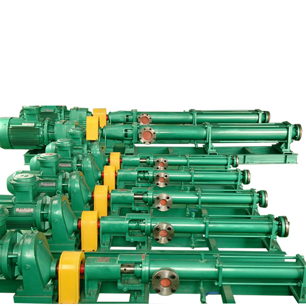
There are two designs for the positive displacement pumps: either reciprocating (such as the plunger and piston design) or rotary (progressing-cavity pumps and rotary vane vacuum pumps being examples).
Slurry pumps are the type of pumps that are appropriate for pumping slurry. Choosing the suitable pump will depend on the size and types of solids in the slurry liquid and how corrosive the slurry mixture is. The larger and more corrosive the slurry is, the more heavy-duty the pumps would need to be.
Centrifugal pumpsare mainly used for slurry at concentrations less than seventy percent solid by weight; and come in various appearances, such as horizontal, submersible, and vertical.
Positive displacement slurry pumps are more limited when it comes to capacity, but they are better for pumping slurry with higher concentrations of solid material.
Centrifugal pumps, such asBianco Vulcan centrifugal pumpare above ground pumps that can be added to existing pump lines to add more power and suction force to the set up. In comparison,submersible drainage pumpssuch as theNova submersible pumpare powerful pumps ideal for removing water from an area, either on a daily basis or in case of emergencies.
Positive displacement slurry pumps are more limited when it comes to capacity, but they are better for pumping slurry with higher concentrations of solid material.
Water pumps differ from slurry or sludge pumps. The viscosity and composition of these fluids mean they need much higher pressure and hydraulic capacity than water pumps. Finally, water pumps cannot withstand potential chemical corrosion and particle abrasion.
Sludge and slurry both contain solid particles, including (but not limited to) sand, gravel, and metals; the difference lies in their consistency. Furthermore, while the liquid in sludge and slurry can indeed be water, it can also contain other types of liquid such as petroleum and various acids.Due to the difference in viscosity and composition of slurry and sludge, installing and using the correct type of pump is imperative.For pumping slurries, a centrifugal pump or heavy-duty drainage pump is used.For pumping sludges, positive displacement pumps such as diaphragm pumps, lobe pumps, and Moyno pumps are best.
A sludge or slurry pump can be used to pump out sewage from sewage lines. The most common type of pumps used for sewage are centrifugal pumps. These pumps can effectively push sewage and can be installed in pits and sumps.
Due to their higher starting costs and complex maintenance, reciprocating pumps are less common than centrifugal pumps. Reciprocating pumps are used in specialised cases when a larger-than-normal quantity of sewage needs to be pumped.
If you are dealing with a small amount of sewage that doesn’t justify the need to construct a pumping station, you can use air pressure pumps or pneumatic ejectors. Unlike other pumps with spinning impellers or pistons, these pumps use compressed air to move sewage. These small-capacity pumps are quieter, have fewer moving parts, and develop blockages less frequently. However, they are the least efficient among the pumping options available.
Because there are several conditions where a slurry pump or a sludge pump is called for, there are three types of installations to consider: dry installation, semi-dry installation or wet installation, which involves fully submerging the pump.
First is a dry installation where the bearings and the pump drive are kept out of the sludge or slurry. The wet end—which may include the impeller, suction liner, shaft sleeve, and shell—is free-standing and out of the way of any liquid. Horizontal slurry pumps are mostly dry installations.
The second method is semi-dry installation. The operator floods the wet end and the bearings but keeps the drive dry. This installation is often used for dredging with horizontal pumps.
The final method is wet installation. Using this method, the slurry pump and drive are fully submerged. Wet installation is often reserved for underwater operations, cement plants, dyeing and printing plants, and similar industries. The pumps used are oftenvertical centrifugal pumpswith semi-open impellers.
A pump is cavitating when the liquid in the pump turns to vapour at low pressure. Cavitation happens when voids (or bubbles) form within the slurry because the pressure rapidly decreases below the vapour pressure.
Sewage ejector pumps can pump high volumes of sewage to a maximum of about230 metres. Septic grinder pumps are better for low volumes but can pump sewage a much longer distance.
The type of pump needed depends on the type of wastewater that needs to be pumped. Centrifugal pumps are good for sludge wastewater with less particulates or solids. Rotary lobe pumps are great for thicker or more viscous fluids. Progressive cavity pumps and the air-operated diaphragm pumps are also suitable for sludge.
While it is possible to pump mud, it’s difficult and complex, so it requires specialised equipment. A reciprocating piston-driven or plunger-driven pump specially made to pump mud is needed for the task, and these can be expensive.
It’s best to have a pump professionally installed by a licensed specialist. Slurry pumps are intricate systems that won’t work correctly if not installed properly. To avoid issues with your slurry pump system, we always recommend getting it professionally installed.

Discharge Head: This is the vertical distance that you are able to pump liquid. For example, if your pump is rated for a maximum head of 18 feet, this does not mean that you are restricted to 18 feet of pipe. You can use 300 feet, so long as the final discharge point is not higher than 18 feet above the liquid being pumped.
Suction Lift: This is the vertical distance that the pump can be above the liquid source. Typically, atmospheric pressure limits vertical suction lift of pumps to 25 feet at sea level. This does not mean that you are limited to 25 feet of pipe. You could use upwards of 300 feet of suction pipe, so long as the liquid source is not lower than 25 feet below the pump center line.

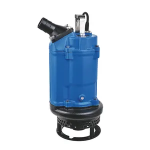
Pump body thick. The pump body is made of high quality pig iron, durable and equipped with a thickened base. Thickened impeller, wear-resistant and dry rotating.
(Place the vertical mud pump upright or tilted in the liquid. Make sure the pump case is completely submerged in water. In addition, the motor part can not be immersed in water.)
Sewage pump is mainly used for industrial sewage, sewage treatment, in environmental protection has played a great role. The sewage pump is also a sewage pump with a cutting wheel, so the sewage pump can cut up the dirt, and then the sewage is extracted clean. Mud pump without cutting impeller, mostly used for pumping mud. The two main performance parameters of mud pump are displacement and pressure, displacement to discharge a number of liters per minute calculation, and drilling diameter and the required flushing fluid from the bottom of the hole back speed, that is, the larger the aperture, the larger the required displacement. The upward return velocity of the flushing fluid is required to flush cuttings and rock powders removed from the bottom of the hole in time and carry them reliably to the surface. By drilling and pumping, the mud under the ground can be obtained.
The present invention provides a vertical sewage treatment device, comprising an anaerobic chamber, an anoxic chamber, an aerobiotic chamber, and a secondary precipitation chamber, wherein the anaerobic chamber, the anoxic chamber, the aerobiotic chamber, and the secondary precipitation chamber are vertically arranged in sequence from the bottom to the top. According to another aspect, the present invention also provides a sewage treatment method using the foregoing vertical sewage treatment device. The sewage treatment device and method of the present invention have the advantages such as a reduced occupied area, improved oxygenation efficiency, a decreased head loss, a reduced invalid structure volume, and a low heat loss.
A sewage treatment plant employing a sewage treatment process of the activated sludge method generally adopts the following flow taking A2O process as a example: the sewage first passes through a grid, enters a grit chamber, a primary sedimentation tank, an anaerobic tank, an anoxic tank, an aerobic tank and a secondary sedimentation tank after lifted by a water pump, finally the treated water reaching an emission standard is drained out. In a sewage treatment plant, various treatment units are generally arranged horizontally. To enable the sewage to smoothly pass through the various treatment units from front to back, a free water surface of a later treatment unit shall be lower than that of a previous treatment unit, and a height difference of these two water surfaces shall be able to satisfy head loss of the sewage passing through a connection pipeline.
In view of this, the present invention provides a vertical sewage treatment device and method that overcome the above described drawbacks of existing horizontal sewage treatment process.
At one aspect, the present invention provides a vertical sewage treatment device comprising an anaerobic compartment, an anoxic compartment, an aerobic compartment and a secondary sedimentation compartment, wherein the anaerobic compartment, the anoxic compartment, the aerobic compartment and the secondary sedimentation compartment are vertically arranged in sequence from bottom to top.
At another aspect, the present invention further provides a method of treating sewage using the above described vertical sewage treatment device comprising the following steps: (1) performing a primary treatment on the sewage through a grit chamber and a primary sedimentation tank;
(2) enabling the sewage to enter from underneath the vertical sewage treatment device, under a pressure of a sewage pump, to the anaerobic compartment, the anoxic compartment, the aerobic compartment and the secondary sedimentation compartment in sequence, and finally draining out water from above.
wherein 1 is an anaerobic compartment of a vertical sewage treatment construction, 2 is an anoxic compartment, 3 is an aerobic compartment, 4 is a secondary sedimentation compartment, 5 is a horizontal mesh, 6 is a mixed liquid passageway from the aerobic compartment to the secondary sedimentation compartment, 7 is inflow water, 8 is a mixing pump for an anaerobic compartment and pipeline, 9 is a sludge backflow pump and pipeline, 10 is a backflow pump for a mixed liquid of the aerobic compartment to the anoxic compartment and pipeline, 11 is a mixing pump for the anoxic compartment and pipeline, 12 is a jet aerator, 13 is a booster pump, 14 is a blower, 15 is a mud-sucking pipe for the secondary sedimentation compartment, 16 is a mud-sucking machine for the secondary sedimentation compartment, 17 is a gas exhaust pipe for the aerobic compartment, 18 is a gas exhaust outlet gas-water separator, and 19 is outflow water.
A vertical sewage treatment device according to the present invention mainly comprises an anaerobic compartment 1, an anoxic compartment 2, an aerobic compartment 3 and a secondary sedimentation compartment 4 which are vertically arranged in sequence from bottom to top. A horizontal orifice plate or mesh 5 is employed to mesh divide between the anaerobic compartment 1 and anoxic compartment 2 and between the anoxic compartment 2 and the aerobic compartment 3 which are vertically arranged up and down. On the one hand, the horizontal orifice plate or mesh 5 enables the sewage to pass therethrough evenly from a lower compartment to an upper compartment and also has a certain barrier function so that large convection of mixed liquid is not generated between different compartments. On the other hand, the horizontal orifice plate or mesh 5 functions as a reinforced structure to the construction. A horizontal grid plate is employed to mesh divide between the aerobic compartment 3 and the secondary sedimentation compartment 4 which are arranged up and down. The horizontal grid plate is both a top plate of the aerobic compartment 3 and a bottom plate of the secondary sedimentation compartment 4. Furthermore, a passageway 6 for the mixed liquid of the aerobic compartment 3 to enter the secondary sedimentation compartment 4 is provided at a side of the horizontal grid plate. At a side of the passageway 6, the horizontal grid plate connects a downwardly vertical grid plate, a height of which is greater than that of a gas-liquid separation area in the aerobic compartment (see the left side of Fig. 2). The passageway 6 only permits the mixed liquid of the aerobic compartment 3 to enter the secondary sedimentation compartment 4 and does not permit a gas to pass through.
In the present invention, a mixing pump 8, a sludge backflow pump 9 and pipelines are arranged at both sides out of the anaerobic compartment 1. The mixing pump 8 mixes the newly-entering sewage in the anaerobic compartment 1 with backflow sludge. The sludge backflow pump 9 transports sedimented sludge in the secondary sedimentation compartment 4 to the anaerobic compartment 1, the amount of the transported sedimented sludge (i.e. the amount of backflow) is generally 40-100% of the amount of inflow water.
In the present invention, a mixing pump 11, a backflow pump 10 for the mixed liquid of the aerobic compartment to the anoxic compartment and pipelines are arranged at both sides out of the anoxic compartment 2. The mixing pump 11 mixes the mixed liquid in the anoxic compartment 2. The mixed liquid backflow pump 10 transports the mixed liquid of the aerobic compartment 3 to the anoxic compartment 2, the amount of the transported mixed liquid (i.e. the amount of backflow) is generally 100-400% of the amount of inflow water.
In the present invention, a jet aerator 12, a booster pump 13 and a blower 14 are arranged at both sides out of the aerobic compartment 3 so as to provide oxygen for a biological reaction in the aerobic compartment. A gas exhaust pipe 17 is arranged on the top of the aerobic compartment 3 to exhaust waste gas in the gas-water separation area on the top of the aerobic compartment 3. To improve aeration pressure and thereby improve aeration oxygenation efficiency in the aerobic compartment 3, a gas exhaust outlet of the gas exhaust pipe 17 of the aerobic compartment 3 is disposed above a water surface of the secondary sedimentation compartment 4, a gas-water separator 18 such as a gravity-type gas-water separator, is disposed at the gas exhaust outlet to ensure that there is a certain pressure within the gas-water separation area of the aerobic compartment 3 such that the mixed liquid within the aerobic compartment 3 does not flow out of the gas exhaust pipe 17. A pressure of gas within the gas-water separator 18 is equal to a sum of an atmospheric pressure and a water level pressure difference between the water surface of the secondary sedimentation compartment 4 and the water surface of the aerobic compartment 3. A water-spraying apparatus is provided within the gas exhaust pipe 17 so as to eliminate foams and scum generated on a surface of the aerobic compartment 3.
In the present invention, a mud-sucking pipe 15 is arranged within the secondary sedimentation compartment 4, a mud-sucking machine 16 is disposed on the top of the mud-sucking pipe 15. Sedimented sludge on the bottom of the secondary sedimentation compartment 4 is sucked out by the mud-sucking machine 16 via the mud-sucking pipe 15, a part of the sucked sedimented sludge flows back to the anaerobic compartment 1 to re-participate in a biological degradation reaction, the other part of the sucked sedimented sludge is drained out in a form of remaining sludge.
A planar dimension of the device of the present invention is determined by dividing an amount of sewage by a surface hydraulic load of the secondary sedimentation compartment, namely, an area of a secondary sedimentation tank, a longitudinal height is determined by dividing a product of a sewage flow and a stay time in various biological treatment compartments by a planar area. When a large amount of sewage needs to be treated, multiple sets of individual devices may operate in parallel. When the multiple sets of individual devices operate in parallel, it needs to employ an underwater equipment corridor, within which external devices such as a mixing pump, a jet aerator, a booster pump and a blower and the like outside the various compartments are arranged to facilitate technician"s management and maintenance.
The sewage treatment procedure using the vertical sewage treatment device according to the present invention is as follows: taking A2O process as an example for illustration, sewage first goes through a grit chamber and a primary sedimentation tank. If suspended matters in the sewage do not have a high concentration, the primary sedimentation tank may be omitted as usual, to retain sufficient organic carbon source in the sewage to meet a need for carbon source during denitrification. It may be considered that the sewage, after passing through the grit chamber, is pressurized by a water pump to enter into the vertical sewage treatment device.
Then, the sewage enters the anaerobic compartment 1, within which original sewage 7 is mixed with the backflow sludge transported from the sludge backflow pump 9 by the mixing pump 8, phosphorus accumulating bacteria in the sludge perform anaerobic phosphorus release utilizing dissolved organics in the original sewage.
The mixed liquid in the anaerobic compartment 1 then enters the anoxic compartment 2 via the horizontal orifice plate or mesh 5. In the anoxic compartment 2, denitrifying bacteria in such sludge perform denitrification utilizing remaining organics and nitrate in the mixed liquid of the aerobic compartment 3 transported by the backflow pump 10 under the mixing of the mixing pump 11.
Upon the completion of denitrification, the mixed liquid in the anoxic compartment 2 enters the aerobic compartment 3 via the horizontal orifice plate or mesh 5. The jet aerator 12, the booster pump 13 and the blower 14 arranged on both sides of the aerobic compartment provide oxygen for a biological reaction in the aerobic compartment 3. Nitrifying bacteria in such sludge perform nitrification under an oxygen-rich condition to transform ammonia nitrogen in the sewage into nitrate, meanwhile phosphorus accumulating bacteria perform aerobic phosphorus absorption, the remaining organics are also oxidized by aerobic bacteria here. The gas exhaust pipe 17 arranged on the top of the aerobic compartment 3 exhausts the waste gas in the gas-water separation area on the top of the aerobic compartment 3.
The mixed liquid in the aerobic compartment 3 enters the secondary sedimentation compartment 4 via the passageway 6. A mud-water separation is performed on the entered mixed liquid in the secondary sedimentation compartment 4. The treated water is drained out via a water outlet 19, sedimented sludge returns to the anaerobic compartment 1 through the mud-sucking pipe 15, the mud-sucking machine 16 and the sludge backflow pump 9, phosphorous is drained out in a form of remaining phosphorus-rich sludge.
A vertical sewage treatment device, comprising an anaerobic compartment (1), an anoxic compartment (2), an aerobic compartment (3) and a secondary sedimentation compartment (4), wherein the anaerobic compartment (1), the anoxic compartment (2), the aerobic compartment (3) and the secondary sedimentation compartment (4) are vertically arranged in sequence from bottom to top.
The vertical sewage treatment device according to claim 1, wherein both sides out of the anaerobic compartment (1) are arranged with a first mixing pump (8), a sludge backflow pump (9) and pipelines; the sludge backflow pump (9) transporting sedimented sludge in the secondary sedimentation compartment (4) to the anaerobic compartment (1), the mixing pump (8) mixing newly-entering sewage in the anaerobic compartment (1) with backflow sludge.
The vertical sewage treatment device according to claim 2, wherein both sides out of the anoxic compartment (2) are arranged with a second mixing pump (11), a mixed liquid backflow pump (10) and pipelines, the mixed liquid backflow pump (10) transporting mixed liquid of the aerobic compartment (3) to the anoxic compartment (2), the second mixing pump (11) mixing the mixed liquid in the anoxic compartment (2).
The vertical sewage treatment device according to claim 3, wherein a jet aerator (12), a booster pump (13) and a blower (14) are arranged at both sides out of the aerobic compartment (3) so as to provide oxygen for a biological reaction within the aerobic compartment (3).
The vertical sewage treatment device according to claim 4, wherein a gas aerated in the aerobic compartment (3) rises to a gas-water separation area on the top thereof, is exhausted via a gas exhaust pipe (17).
The vertical sewage treatment device according to claim 5, wherein a gas-water separator (18) is disposed at an outlet of the gas exhaust pipe (17); a water-spraying apparatus is disposed within the gas exhaust pipe (17), for eliminating foams and scum generated on a surface of the aerobic compartment (3).
The vertical sewage treatment device according to any of claims 1 to 6, wherein a mud-sucking pipe (15) is arranged within the secondary sedimentation compartment (4), a mud-sucking machine (16) is disposed on the top of the mud-sucking pipe (15), sedimented sludge on a bottom of the secondary sedimentation compartment (4) is sucked out by the mud-sucking machine (16) via the mud-sucking pipe (15), a part of the sucked sedimented sludge flows by the sludge backflow pump (9) back to the anaerobic compartment (1) as the backflow sludge to re-participate in a biological degradation reaction, the other part of the sucked sedimented sludge is drained out in a form of remaining sludge.
The vertical sewage treatment device according to any of claims 1 to 6, wherein a horizontal orifice plate or mesh (5) is employed to mesh divide between the anaerobic compartment (1) and the anoxic compartment (2) and between the anoxic compartment (2) and the aerobic compartment (3).
The vertical sewage treatment device according to any of claims 1 to 6, wherein a horizontal grid plate is employed to mesh divide between the aerobic compartment (3) and the secondary sedimentation compartment (4), and a side of the horizontal grid plate is retained with a passageway (6) for the mixed liquid within the aerobic compartment (3) to enter the secondary sedimentation compartment (4), and at a side of the passageway (6), the horizontal grid plate connects a downwardly vertical grid plate, a height of which is greater than that of a gas-water separation area in the aerobic compartment (3).
The vertical sewage treatment device according to any of claims 1 to 6, wherein when multiple sets of vertical sewage treatment devices operate in parallel, an underwater equipment corridor is employed, and the first mixing pump (8), the second mixing pump (11), the jet aerator (12), the booster pump (13) and blower (14) of various devices are arranged in the underwater equipment corridor.
(2) enabling the sewage to enter from underneath the vertical sewage treatment device, under a pressure of a sewage pump, to the anaerobic compartment, the anoxic compartment, the aerobic compartment and the secondary sedimentation compartment in sequence, and finally draining out water from above;


 8613371530291