
vertical mud pump pricelist free sample

Explore a wide variety of vertical mud pump on Alibaba.com and enjoy exquisite deals. The machines help maintain drilling mud circulation throughout the project. There are many models and brands available, each with outstanding value. These vertical mud pump are efficient, durable, and completely waterproof. They are designed to lift water and mud with efficiency without using much energy or taking a lot of space.
The primary advantage of these vertical mud pump is that they can raise water from greater depths. With the fast-changing technology, purchase machines that come with the best technology for optimum results. They should be well adapted to the overall configuration of the installation to perform various operations. Hence, quality products are needed for more efficiency and enjoyment of the machines" full life expectancy.
Alibaba.com offers a wide selection of products with innovative features. The products are designed for a wide range of flow rates that differ by brand. They provide cost-effective options catering to different consumer needs. When choosing the right vertical mud pump for the drilling project, consider factors such as size, shape, and machine cost. More powerful tools are needed when dealing with large projects such as agriculture or irrigation.
Alibaba.com provides a wide range of vertical mud pump to suit different tastes and budgets. The site has a large assortment of products from major suppliers on the market. The products are made of durable materials to avoid corrosion and premature wear during operations. The range of products and brands on the site assures quality and good value for money.

A wide variety of mud pump price list options are available to you, such as 1 year, 2 years and 3 years.You can also choose from new, mud pump price list,As well as from energy & mining, construction works , and machinery repair shops. And whether mud pump price list is 1.5 years, {2}, or {3}.

An innovative product policy and continuous advancement of essential design features make this pump a powerful, yet economical standard unit with a broad range of applications.
Professional China Mud Pump - BNS series Single Stage, End Suction Norm Centrifugal pumps – Beken, The product will supply to all over the world, such as: , , ,
The “pond” is actually a man made dam which covers an area of about 40ha and has rockfill embankments of up to 53m high along the southern side that forms the impoundment. It initially constructed in 1959 to act as a tailings pond to take the bauxite residue (red mud) from the Ewarton Plant situated about 5km away and 300m lower. The red mud was pumped as a slurry comprising about 20% solids to the pond over a period of about 32 years up to 1991 when the pond was replaced by the Charlemount Mud Stacking and Drying Facility. During this period the pond embankments (referred to as dams), were raised up to 7 times providing a final crest elevation of 472m. The pond was however never filled to its final design capacity and the mud beach level remained at about 469m and the central area about 458m leaving a concave depression which held about 1.4mil m3 of water with elevated pH and some caustic content.
The remediation plan for the pond includes the removal of the ponded water and then the regrading of the mud surface to be free draining so that it can be stabilised and vegetated. About 500,000 m3 of mud will need to be moved over a distance of up to 1km in order to create the required profile. Due to the very soft nature of the surface muds (shear strength of less than 3kPa) its bearing capacity is less than 20kPa hence it is not accessible using even modified earthworks equipment. In addition, the muds are thyrotrophic and under any vibration or shear loading, rapidly liquefy resulting in significant reduction in shear strength and loss of bearing capacity. Using conventional earthmoving equipment would therefore require extensive “floating” haul roads with a high risk of machinery getting stuck or entire plant loss and risk to personnel. It was therefore decided to investigate the possibility of pumping the in-situ red mud.
A mud pumping trial was undertaken to assess the feasibility of using this technique to do the bulk mud moving. Pumping red mud is not unusual and the muds were initially pumped up to Mt Rosser Pond. However, the muds are usually pumped at a solids content of 30% or less. Once deposited, they can take years to reconsolidate and firm up sufficiently to allow access for light earthworks and agricultural plant.
In addition to the mud pumping, the trial included infilling three small scale geotubes to assess their performance as these may be needed as part of the regrading works.
The main aim of the pump trial was to determine if the muds could be pumped in their insitu state, and if not, what amount of water is required and how the variations in water content affect pump rates.
The mud pumping trial was undertaken using a 4” EDDY Pump. This pump was recommended due to its ability to handle variable solids and robust operating mechanism. The pump unit incorporated a hydraulic drive and cutter head. The unit was mounted onto the boom of a JCB 220 excavator which also supplied the hydraulic feed to power the pump for the required range of 30-40 GPM at 3,500 to 4,000 psi (2428MPa). The cutter head was powered by a standalone hydraulic power unit capable of providing the required 30gpm at 200psi (1.9 l/s at 13.8MPa). If mounted on a 30-ton excavator with a System 14 hydraulic system and dual auxiliary feeds to the boom, all necessary hydraulic power for the pump and cutter head can be supplied by the excavator. This equipment was however not available at the time in Jamaica.
In addition to the pump mounted on the excavator a Long Reach excavator (CAT 325) was used to move muds towards the cutter head but also to loosen up the muds and mix in additional water to facilitate pumping. Water was added by pumping it directly from the pond using a 3” diesel water pump.
Prior to pumping the muds, the mud pump would operate in recirculation mode in order to prime the pump. When in recirculation (re-circ) mode, the material pumped would be diverted to a short discharge pipe mounted on the pump directed back parallel to the cutter head. This action would help agitate and stir the muds.
A geotechnical soils investigation was undertaken on the muds within Mt Rosser pond in 2004. It showed the material to be predominantly clayey silt with approximately 13% sand, 29% clay and 58% silt using conventional sieve analysis and hydrometer. Atterberg limits indicate that the material is an intermediate to high plasticity clay. The muds do however vary across the lake and also vertically. This is mainly as a consequence of the deposition process and discharge location. Close to the discharge location the courser materials would settle out first and the finer materials would disperse furthest and to the opposite end of the pond. The results are presented in figure 4.1.
Earlier this year, additional mud samples were tested as it was evident that standard soil mechanics tests did not provide an accurate assessment of this fine material. This was particularly evident in tests done with dry sieving which shows the material as well-graded sand (see results for samples 5300, 5301, 5302 on figure 4.2). When dispersed in water, even with an agent, the ‘yield-pseudo-plastic’ rheology of the muds appeared to affect the hydrometer results with large variations between tests (see results of samples PFT4&5 taken during mud pumping trials on figure 4.2).
The additional testing comprised of undertaking gradings using a Laser Particle Analyzer. The results indicated that the muds are predominantly Silt although the silt % varied from 30% to 80% with the material being either more sandy or more clayey (up to 15% clay). See results of samples ending in “L” on figure 4.2 below.
Moisture content tests on the muds taken from within the mud pond but below the ponded water ranged from 100% to 150% (50% to 40% solids). The muds at the pump test location were 137% (42% solids).
Shear strength was generally very low ranging from 1kPa to 6kPa increasing with depth. Dynamic probes previously undertaken indicated that the muds are “very soft” to 5m increasing in strength slightly to “soft” at a depth of 9m after which they increase to firm becoming stiff.
The pH of the muds ranged from 10.3 to 11.7, (ave 11.2). Previous testing indicated that the surface muds have the lower pH although once through the crust, the pH tends to be higher. When doing the trials, the muds up to a depth of about 2.5m was intermixed, hence any stratification in pH could not be determined.
Initially, pumping was problematic mainly due to the excavator being underpowered. This was diagnosed as a hydraulic pump problem and the excavator was replaced. The cutter head (which also acts to protect the intake) tended to blind with mud (Photo 5.1) and was also not providing enough agitation to liquefy the muds. This was partly resolved by adding “stirrers” (2 steel loops welded either side) to the rotating cutter head and also a “comb” (Photo 5.2) to keep the gaps within the cutter head open.
Mud pumping rates varied from 21 l/s to 52 l/s (332 – 824gpm) and it was clearly visible that the more liquid the muds were the higher the pump rate was. Samples were taken at different discharge rates and moisture content and percent solids determined by laboratory testing. The results are plotted in Figure 5.1 and although scattered, do give an indication of the effects of solids content on flow rates. The natural moisture content of the muds (insitu) at the test location was 137%, or 42% solids. This is shown in Figure 5.1 as a vertical line. Pumping muds close to the percent solids was achieved although flow rates were low.
As mentioned previously, the long reach excavator was used to loosen up the muds. Water was pumped from the pond using a 3” pump into the excavation and the long reach would then work the muds to mix the water in. The mud pump would then be used in recirculation mode to further mix the muds into a more consistent state. Even with this mixing and agitation, the water tended to concentrate on the surface. This aided the initial process of priming the pump and once primed thicker muds at 1m to 2m below the surface could be pumped. However, it was found that the deeper muds tended to be lumpy and this would significantly reduce or stop the flow requiring the pump to be lifted into thinner muds or having to go back into re-circ mode or having to fully re-prime. The pump discharge was therefore very inconsistent as the suction intake position constantly needed adjustment in an attempt to get adequate discharge but also pump the thickest muds possible.
Discharge of the pumped muds was through 30m of flexible hose then 60m of 4” HDPE pipe which had an internal diameter of about 87mm (3.5”). The muds were discharged onto the original mud beach which lies at a gradient of about 9%. On deposition the muds slowly flowed down gradient. At times the flow would stop and the muds would build up then flow again in a wave motion. The natural angle of repose would therefore be a few degrees less than this – probably 5% to 6%.
Although the muds have very low shear strength, and on agitation liquefy, the sides of the excavation had sufficient strength to stand about 2m near vertical. Even overnight, there was limited slumping and the bank could be undermined by about 0.5m with the cutter head/agitator before collapsing.
On termination of pumping, in order to flush the pipeline, thin watery muds were pumped until the line was clear. A “T” valve system was then used to connect the 3” water pump line and this was then used to flush the pipe with water.
Three geotubes (1m x 6m) were filled with red muds pumped using the 4” Eddy pump. Fill rates were about 30 to 40l/s although it was difficult to assess as the flow and mud consistence was not visible.
Tube 1 was filled initially with more runny mud and then thicker muds as the pump operator got a better feel for conditions. The tube was filled until firm. The second tube was filled with thicker muds and filling continued until the tube was taut. These two tubes were positioned on the sloping beach in order to form a small “U” impoundment area that would later be filled with pumped muds. Although the area was prepared, the sloping ground caused the first tube to rotate through about 20 degrees. The tube was staked and the downslope side backfilled. A more defined bed was created for the second tube and the same rotational issue was limited. The two filled tubes with the ponded mud are shown in Photos 5.7 and 5.8. Other than a small leak at the contact between the two geotubes, the ponding of the muds was successful.
The third tube was positioned on level ground. It was filled with medium runny (but consistent thickness) muds and was filled until the tube was taut.
In all three cases, there was very little mud loss or seepage from the tubes. When stood on, some red water would squeeze out around the pressure area. Once filled taut, the entire bag would have small red water droplets form on the outside (visible in Photo 5.11) , but the seepage was in general nominal.
The tubes have been monitored and the most recent photo’s taken on 10 October 2011 (6 weeks after filling) show how the tubes have reduced in volume due to the dewatering of the contained muds. Volume loss is estimated to be around 30%. The anticipated moisture content would therefore be about 90% and the solids around 53%.
The muds pumped into the trial pond behind the geotubes were medium thick to thick, probably in the order of 37 – 40% solids. After 6 weeks the mud has not only firmed-up but had dried out significantly with wide and deep surface cracks as are evident in Photo 5.14 and 5.15.
The muds can be pumped at close to their insitu moisture content and most likely at their in-situ moisture content if they were agitated more and the pipeline system was designed to reduce friction losses.
Be able to access the mud surface and move around efficiently and safely. The suggestion is to have the pump mounted on a pontoon that is positioned using high strength rope (dynema) or steel cable. The pump system should be remotely controlled as this would limit regular movement of personnel on the muds.
Have sufficient power and volume capacity to pump the muds at close to or at in-situ moisture content and discharge them about 1000m through a flexible pipeline.
It was also evident from the trials that the muds do not slump and flow readily. It will therefore be necessary to have an amphibious excavator to loosen up the muds in the area around the pump head. This weakened and more liquid mud would also aid the movement of the pump pontoon. To also limit the amount of movement the pontoon will need to do, the amphibious excavator could also move muds towards the pump location.
Using the capacity of the 4” mud pump, mud moving would take about 1.5 to 2 years, the pump will however need to be more suited to the task. A target period of 1 year however seems reasonable. However, prior to this, equipment will need to be procured and imported into Jamaica. The 6 and 10 inch Excavator Dredge Pump Attachments are also being considered as an option for higher GMP and a more aggressive completion timeline. A preliminary programme is as follows:

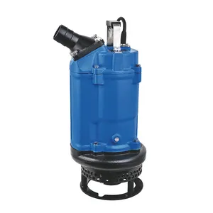
5 hp vertical mud pump with pure copper motor and thick pump body. Motor with fan heat dissipation, dehydration use will not burn submersible mud pump.
Pump body thick. The pump body is made of high quality pig iron, durable and equipped with a thickened base. Thickened impeller, wear-resistant and dry rotating.
(Place the vertical mud pump upright or tilted in the liquid. Make sure the pump case is completely submerged in water. In addition, the motor part can not be immersed in water.)
The bottom of the pump should avoid large particles into the stuck impeller, such as found that the pump does not turn should immediately stop the inspection.
When analyzing a heavy duty sludge pump, there are some tips in the while reading the overview. The heavy-duty, rubber-lined slurry pump is specifically designed to handle large quantities of abrasives and soft solids containing fibrous particles at high flow rates. These pumps are commonly used in the mining, paper, construction, and agricultural industries, it is designed to handle a wide variety of liquids, from manure or bulk animal waste to chemical sludge, sludge, lime, fly ash, gravel, and mineral products. Applications range from transfer to filter press feed and water/steam jet. The inner volute is lined with rubber to reduce the wear rate of the device, and the impeller is covered with rubber to ensure the service life. This slurry pump design has a forward and reverses adjustment feature that adjusts the internal clearance based on bushing wear.
The overview of heavy duty sludge pump is a brief description of how the pump works and what are the components. A pump is a set of mechanical devices that transfer fluid from one part to another by increasing the pressure of the fluid. There are different types of pumps, classified by use and shape, the best known of which are centrifugal pumps, booster pumps, electric pumps, domestic pumps, car washes, etc. it is clarified that each type has a different type according to the number of production heads, power and efficiency, and other advantages and disadvantages, taking into account the needs of users, preparing for it. Design engineers in different industries use different pumps in their designs depending on the required head, type of fluid, project requirements and viscosity, diagrams, economical materials, etc. The sludge pump can be configured with a choice of 4 impeller types:
Vortex Turbine: Used to convey large concentrations of bulk solids at low pressure. Due to the vortex design of the impeller, the area in contact with the fluid is smaller and therefore less efficient. They are required for clog-free pumping of fluids containing abrasive solids.
heavy duty sludge pump plays an important role in water and wastewater treatment plants and pumping stations. By checking the pump reviews, it is easier to choose a proper pump. Ease of maintenance and repair is an important consideration for those responsible for keeping the pump in good working order. Pumping station pumps transport the waste from the source to the treatment plant, from where the pumps are used to move influent, raw water, primary sludge, and secondary sludge, and return activated sludge to the final effluent. Centrifugal pumps are one of the most commonly used pumps in sewage treatment plants and pumping stations. In the past, dry-pit (or non-clogging) solids-handling pumps with flexible drive shafts and premium motors were probably the most popular type of pump for sewage treatment plants and PSs. Today, municipalities are evaluating the advantages of using dry pit pumps over dry pit submersibles and true submersible (wet pit) pumps. There are different opinions as to which is best, as each has its own pros and cons. In the field of sludge pumping, different types of specialized pumps are used, from ejectors to positive displacement pumps, but in practice the most common pumps in the field of sludge pumping are centrifugal pumps. In a mud pump, centrifugal force is used to generate kinetic energy for the mud. To purchase a slurry pump or for the latest slurry pump price, please contact our experts. The material of the mud pump body is often wear-resistant cast iron or wear-resistant metal alloy, and can also be plastic. Slurry pumps are used to move and transport materials containing solid particles. One of the important uses of this pump is using it in mining and transport drilling mud, sometimes these pumps are also called mud transfer pumps.
Since the heavy duty sludge (slurry) pump is often associated with abrasives, some tips are required while dealing with an elastomer or rubber coating. it is used to protect and increase the life of the wear resistance of the parts, so it is also called a pump anti-wear or linear pump. Linear pumps are widely used in the tile and ceramic industry to transport slurries and fluids containing silica and similar industries. Various pumps are used for slurry suction, including special types of pumps such as positive displacement pumps and ejectors; however, the most common slurry pump is the centrifugal pump. In centrifugal slurry pumps, as in clean liquid centrifugal pumps, centrifugal force (generated by the impeller) is used to generate kinetic energy for the slurry. But the similarities between centrifugal slurry pumps and clean liquid centrifugal pumps don"t end there. When selecting a centrifugal slurry pump, considerations related to the size and dimensions of the impeller and the type of design of the impeller passages through which the solids pass, good shaft sealing, and Optimal selection of long life materials should be taken into account. Engineers consider the placement of parts that come in contact with the pump fluid. Wetted parts may be subject to abrasion or chemical corrosion. In order to achieve low working speed, the size of the slurry pump is larger than that of the clean water pump. This results in reduced fluid velocity in the pump and minimal wear rates. Axial bearings are becoming stronger in mud pumps and are generally designed for heavy-duty applications. Slurry pumps are widely used in the mining industry and factories mainly use wet separation systems, which often convey large volumes of slurry in their processes. Slurry pumps are also widely used to process fossil fuel residues in power plants.
there are different types of heavy duty sludge pump based on the construction and purpose of use. The slurry pump is divided into two categories: centrifugal pump and peristaltic pump. The most common slurry pump is a centrifugal pump which uses the centrifugal force generated by the propeller to make the slurry flow.
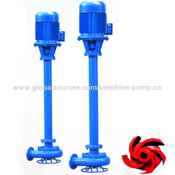
This type of pump is the most common and works based on the centrifugal force created by the impeller of the pump. There are three types of centrifugal slurry pumps: horizontal, vertical and hose slurry pumps, which are mainly used to transport high concentration fluids.
This type of pump has a structure to deliver liquids that require sterile conditions due to their contact with the inside of the tube. Using these pumps is a suitable choice for conveying abrasive laden fluids and shear stress sensitive fluids, and they are also easy to service and maintain. One of the main characteristics of peristalsis is the absence of sealing parts.


 8613371530291